ABB Semiconductors AG
Key Parameters
V
RRM
=
1700 V
I
FAVM
=
1310 A
I
FSM
=
15.0 kA
V
F0
=
0.74 V
r
F
=
0.25 m
Doc. No. 5SYA 1119 - 01 Apr-98
Avalanche Rectifier Diode
5SDA 11D1702
Features
∑
∑
Optimized for line frequency rectifiers
∑
∑
Low on-state voltage, narrow V
F
-bands for parallel operation
∑
∑
Self protected against transient overvoltages
∑
∑
Guaranteed maximum avalanche power dissipation
∑
∑
Industry standard housing
Blocking
Part number
5SDA 11D1702
5SDA 11D1402
5SDA 11D1102
Condition
V
RRM
1700
1400
1100
f
= 50 Hz
t
P
= 10 ms
V
RSM
1870
1540
1200
t
P
= 10 ms
T
j
= 160∞C
I
RRM
50
mA
V
RRM
T
j
= 160∞C
P
RSM
70
kW
t
P
= 20 µs
T
j
=
45∞C
50
kW
t
P
= 20 µs
T
j
= 160∞C
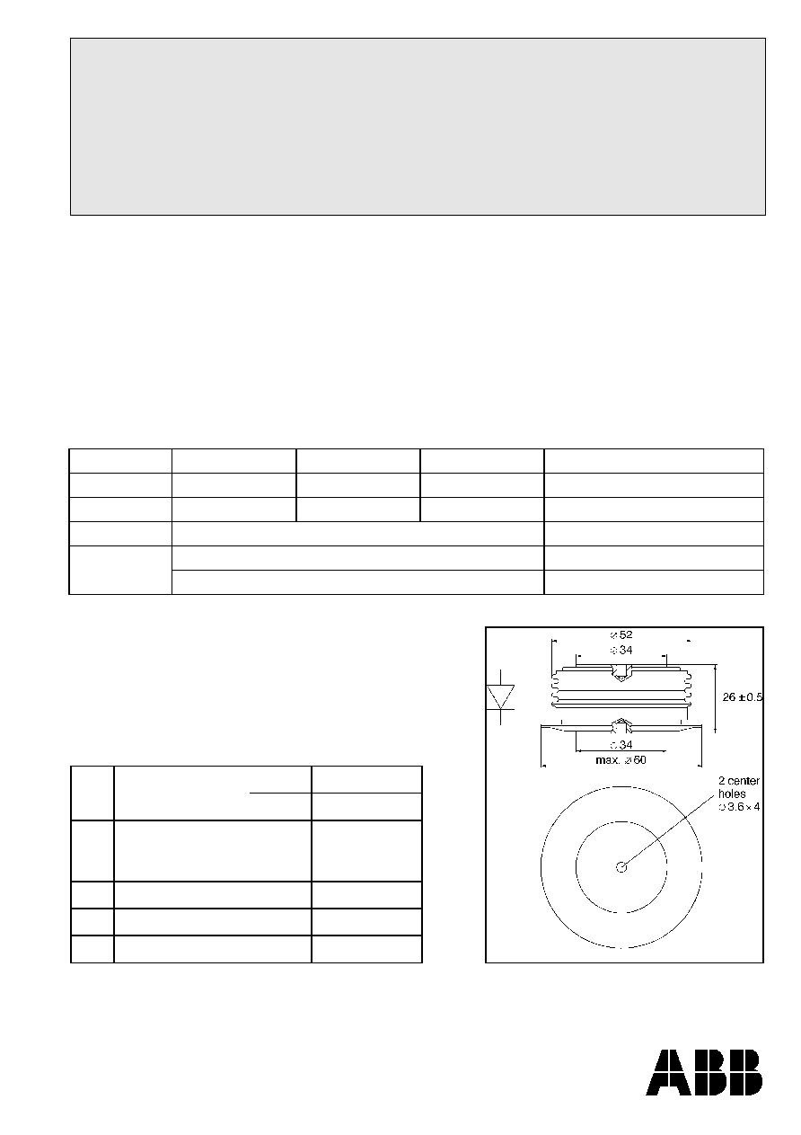
Mechanical data
F
M
Mounting force
min.
10
kN
max.
12
kN
a
Acceleration
Device unclamped
Device clamped
50
200
m/s
2
m/s
2
m
Weight
0.25
kg
D
S
Surface creepage distance
30
mm
D
a
Air strike distance
20.5
mm
ABB Semiconductors AG
5SDA 11D1702
Doc. No. 5SYA 1119-01 Feb-98
ABB Semiconductors AG
Fabrikstrasse 3
CH-5600 Lenzburg, Switzerland
Telephone +41 (0)62 888 6419
Fax +41 (0)62 888 6306
On-state
I
FAVM
Max. average on-state current
1310 A
Half sine wave, T
C
= 85∞C
I
FRMS
Max. RMS on-state current
2060 A
I
FSM
Max. peak non-repetitive
15 kA
tp
=
10 ms
T
j
=
160∞C
surge current
16 kA
tp
=
8.3 ms
After surge:
I
2
t
Limiting load integral
1130
10
3
A
2
s
tp
=
10 ms
V
R
0V
1070
10
3
A
2
s
tp
=
8.3 ms
V
F0
Threshold voltage
0.74 V
I
F
= 1000 - 3000 A
T
j
=
160∞C
r
F
Slope resistance
0.25 m
V
F min
On-state voltage
1.05 V
I
F
=
1800 A
T
j
=
25∞C
V
F max
On-state voltage
1.20 V
Thermal
T
j
Storage and operating
-40...160∞C
junction temperature range
R
thJC
Thermal resistance
80
K/kW
Anode side cooled
junction to case
80
K/kW
Cathode side cooled
40
K/kW
Double side cooled
R
thCH
Thermal resistance case to
16
K/kW
Single side cooled
heat sink
8
K/kW
Double side cooled
For a given case temperature T
c
at ambient temperature T
a
the
maximum on-state current can be calculated as follows:
I
=
-V + (V )
4 * f * r * P
2 * f
r
FAVM
F0
F0
2
f
2
f
2
+
*
where
P =
T
- T
R
J max
C
thjc
or
P =
T
- T
R
J max
A
thja
Analytical function for transient thermal impedance:
Z
(t) =
R (1- e
)
thJC
i
-t /
i 1
4
i
=
i
1
2
3
4
R
(K/kW)
20.95
10.57
7.15
1.33
i
(s)
0.396
0.072
0.009
0.0044
t [s]
10
-3
10
-2
10
-1
10
0
10
1
2
3 4 5 6 7
2
3
4 5 6 7
2
3 4 5 5 6
2
3 4 5 6 7
0
5
10
15
20
25
30
35
40
45
F
m
=10...12 kN
Double Side Cooling
Z
th
[K/kW]
I
FAVM
(A)
P (W)
V
F0
(V)
r
F
(
)
T
max
(∞C)
T
c
(∞C)
T
a
(∞C)
R
thja
(K/kW)
R
thJC
(K/kW)
f
2
=
1
for DC current
2.5
for half-sine wave
3.1
for 120∞el., sine
6
for 60∞ el., sine