
DESCRIPTION
The Accutek AK5322048N high density memory module is a CMOS
dynamic RAM organized in 2048K x 32 bit words. The module con-
sists of four standard 1 Meg x 16 DRAMs in plastic TSOP packages.
The assembly has 2 drams mounted on each side of a printed circuit
board in a 72 pad leadless Dual Row Sodim configuration.
This configuration allows socket-mounting of large quantities of
memory in applications where high density and ease of inserting ad-
ditional memory are important.
The operation of the AK5322048A is identical to four 1M x 16
Drams. There are four
CAS
lines and four
RAS
lines. On each bank
of 1M x 32, independent byte control is accomplished by four
CAS
lines. Each seperate
CAS
line controls one byte of the 1M x 16
Dram. Two banks of 32 bits are controlled by the two pairs of
RAS
lines. A sixteen bit data path can be produced by connecting DQ
0
to
DQ
16
, DQ
1
to DQ
17
etc. and alternately strobing
RAS
0
with
RAS
1
and
RAS
2
with
RAS
3
.
FEATURES
� 2,097,152 x 32 bit organization
� 72 pad Dual Row Sodim Module
� Multiple
CAS
and
RAS
lines allow x16 or x32 bit widths
�
CAS
-before-
RAS
,
RAS
-only or hidden refresh
� Operating free air temperature 0
o
C to 70
o
C
� Single 5 Volt Power Supply
� 1024 Refresh Cycles, 16 mSEC
� Available in Fast Page Mode and Static Column Mode ver-
sions
� Power
1.80 Watt Max Active (60nS)
1.66 Watt Max Active (70 nS)
1.44 Watt Max Active (80 nS)
22 mW Max StandbyAvailable
ADDITIONAL OPTIONS AVAILABLE
1 Meg x 32 version, AK5321024N
Accutek
Microcircuit
Corporation
AK5322048N
2,097,152 Word by 32 Bit CMOS
Dynamic Random Access Memory
1
71
2
72
Front
Side
Back
Side
PIN NOMENCLATURE
DQ
0
- DQ
31
Data In/Data Out
A
0
- A
9
Address Inputs
CAS
0
- CAS
3
Column Address Strobe
RAS
0
- RAS
3
Row Address Strobe
WE
Write Enable
PD
0
- PD
6
Presence Detect
Vcc
5v Supply
Vss
Ground
NC
No Connect
MODULE OPTIONS
Leadless SODIM: AK5322048N
PIN ASSIGNMENT
PIN #
SYMBOL
PIN #
SYMBOL
PIN #
SYMBOL
PIN #
SYMBOL
1
Vss
19
NC
37
DQ16
55
NC
2
DQ0
20
NC
38
DQ17
56
DQ24
3
DQ1
21
DQ8
39
Vss
57
DQ25
4
DQ2
22
DQ9
40
CAS0
58
DQ26
5
DQ3
23
DQ10
41
CAS2
59
DQ28
6
DQ4
24
DQ11
42
CAS3
60
DQ27
7
DQ5
25
DQ12
43
CAS1
61
Vcc
8
DQ6
26
DQ13
44
RAS0
62
DQ29
9
DQ7
27
DQ14
45
RAS1
63
DQ30
10
Vcc
28
A7
46
NC
64
DQ31
11
PD0
29
NC
47
WE
65
NC
12
A0
30
Vcc
48
NC
66
PD1
13
A1
31
A8
49
DQ18
67
PD2
14
A2
32
A9
50
DQ19
68
PD3
15
A3
33
RAS3
51
DQ20
69
PD4
16
A4
34
RAS2
52
DQ21
70
PD5
17
A5
35
DQ15
53
DQ22
71
PD6
18
A6
36
NC
54
DQ23
72
Vss
Presence Detect -
Access
Time
PD
0
PD
1
PD
2
PD
3
PD
4
PD
5
PD
6
-60
NC
Vss
Vss
Vss
NC
NC
NC
-70
NC
Vss
Vss
Vss
Vss
NC
NC
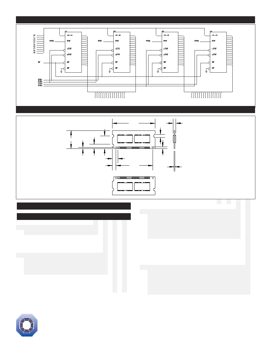
FUNCTIONAL DIAGRAM
MECHANICAL DIMENSIONS
ORDER INFORMATION
PART NUMBER CODING INTERPRETATION
Position
1
2
3
4
5
6
7
8
1
Product
AK
=
Accutek Memory
2
Type
4
= Dynamic RAM
5
= CMOS Dynamic RAM
6
= Static RAM
3
Organization/Word Width
1 = b y 1 16
= by 16
4 = by 4
32
= by 32
8 = by 8
36
= by 36
9 = by 9
4
Size/Bits Depth
64
=
64K
4096
=
4 MEG
256
=
256K
8192
=
8 MEG
1024 =
1 MEG
16384
=
16 MEG
The numbers and coding on this page do not include all variations avail-
able, but are shown as examples of the most widely used variations.
Contact Accutek if other information is required.
Position
1
2
3
4
5
6
7
8
5
Package Type
G = Single In-Line Package (SIP)
S = Single In-Line Module (SIM)
D = Dual In-Line Package (DIP)
W = .050 inch Pitch Edge Connect
N = Dual Row Sodim
Z = Zig-Zag In-Line Package (ZIP)
6
Special Designation
P = Page Mode
N = Nibble Mode
K = Static Column Mode
W = Write Per Bit Mode
V = Video Ram
7
Separator
-
= Commercial 0
0
C to +70
0
C
M = Military Equivalent Screened
(-55
0
C to +125
0
C)
I
= Industrial Temperature Tested
(-45
0
C to +85
0
C)
X = Burned In
8
Speed (first two significant digits)
DRAMS
SRAMS
60
=
60 nS
12
=
12 nS
70
=
70 nS
15
=
15 nS
80
=
80 nS
20
=
20nS
ACCUTEK MICROCIRCUIT CORPORATION
BUSINESS CENTER at NEWBURYPORT
2 NEW PASTURE ROAD, SUITE 1
NEWBURYPORT, MA 01950-4054
PHONE:
978-465-6200
FAX:
978-462-3396
Email:
sales@accutekmicro.com
Internet:
www.accutekmicro.com
Accutek reserves the right to make changes in specifications at any time and with-
out notice. Accutek does not assume any responsibility for the use of any circuitry
described; no circuit patent licenses are implied. Preliminary data sheets contain
minimum and maximum limits based upon design objectives, which are subject to
change upon full characterization over the specific operating conditions.
0.700"
2.350"
0.158"
0.150"
0.100"
0.040"
2.033"
0.197"
0.300"
0.250"
0.070"
1.000"
DQ0
DQ1
DQ2
DQ3
DQ4
DQ5
DQ6
DQ7
DQ8
DQ9
DQ10
DQ11
DQ12
DQ13
DQ14
DQ15
DQ0
DQ1
DQ2
DQ3
DQ4
DQ5
DQ6
DQ7
DQ8
DQ9
DQ10
DQ11
DQ12
DQ13
DQ14
DQ15
DQ0
DQ1
DQ2
DQ3
DQ4
DQ5
DQ6
DQ7
DQ8
DQ9
DQ10
DQ11
DQ12
DQ13
DQ14
DQ15
DQ0
DQ1
DQ2
DQ3
DQ4
DQ5
DQ6
DQ7
DQ8
DQ9
DQ10
DQ11
DQ12
DQ13
DQ14
DQ15
DQ
0
DQ
1
DQ
2
DQ
3
DQ
4
DQ
5
DQ
6
DQ
7
DQ
8
DQ
9
DQ
1
0
DQ
1
1
DQ
1
2
DQ
1
3
DQ
1
4
DQ
1
5
DQ
1
6
DQ
1
7
DQ
1
8
DQ
1
9
DQ
2
0
DQ
2
1
DQ
2
2
DQ
2
3
DQ
2
4
DQ
2
5
DQ
2
6
DQ
2
7
DQ
2
8
DQ
2
9
DQ
3
0
DQ
3
1