 | ÐлекÑÑоннÑй компоненÑ: AD588T | СкаÑаÑÑ:  PDF PDF  ZIP ZIP |
/home/web/doc/html/ad/210870
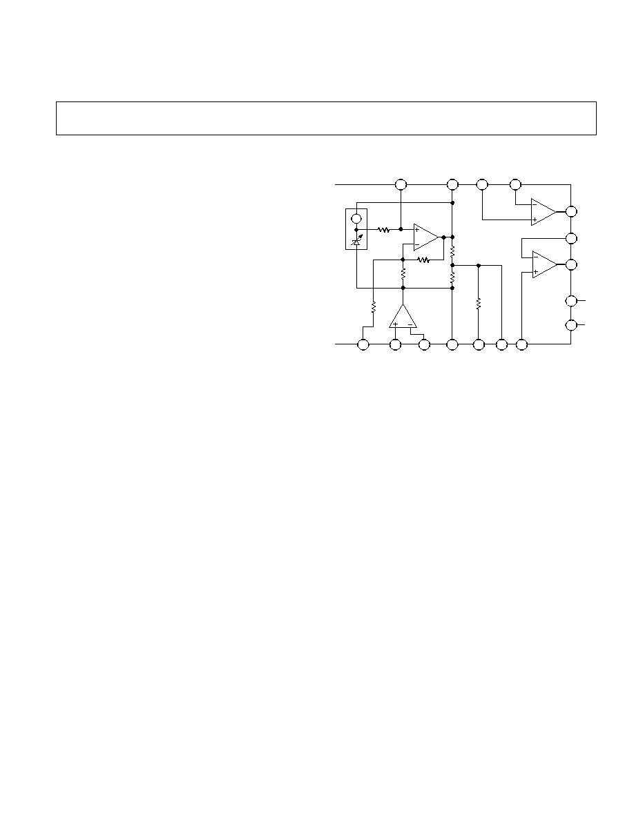
FUNCTIONAL BLOCK DIAGRAM
6
7
4
3
2
1
13
8
9
10
11
12
5
14
15
16
A3
A4
A1
A2
R3
R
B
R1
R2
R4
R5
R6
AD588
GAIN
ADJ
GND
SENSE
+IN
GND
SENSE
IN
V
LOW
BAL
ADJ
V
CT
A4 IN
V
S
+V
S
A4 OUT
FORCE
A4 OUT
SENSE
A3 OUT
FORCE
A3 OUT
SENSE
A3 IN
V
HIGH
NOISE
REDUCTION
REV. B
Information furnished by Analog Devices is believed to be accurate and
reliable. However, no responsibility is assumed by Analog Devices for its
use, nor for any infringements of patents or other rights of third parties
which may result from its use. No license is granted by implication or
otherwise under any patent or patent rights of Analog Devices.
a
High Precision Voltage Reference
AD588*
One Technology Way, P.O. Box 9106, Norwood, MA 02062-9106, U.S.A.
Tel: 617/329-4700
Fax: 617/326-8703
FEATURES
Low Drift: 1.5 ppm/ C
Low Initial Error: 1 mV
Pin-Programmable Output
+10 V, +5 V,
5 V Tracking, 5 V, 10 V
Flexible Output Force and Sense Terminals
High Impedance Ground Sense
Machine-lnsertable DIP Packaging
MIL-STD-883 Compliant Versions Available
PRODUCT DESCRIPTION
The AD588 represents a major advance in the state-of-the-art in
monolithic voltage references. Low initial error and low tem-
perature drift give the AD588 absolute accuracy performance
previously not available in monolithic form. The AD588 uses a
proprietary ion-implanted buried Zener diode, and laser-wafer-
drift trimming of high stability thin-film resistors to provide out-
standing performance at low cost.
The AD588 includes the basic reference cell and three addi-
tional amplifiers which provide pin-programmable output
ranges. The amplifiers are laser-trimmed for low offset and low
drift to maintain the accuracy of the reference. The amplifiers
are configured to allow Kelvin connections to the load and/or
boosters for driving long lines or high-current loads, delivering
the full accuracy of the AD588 where it is required in the appli-
cation circuit.
The low initial error allows the AD588 to be used as a system
reference in precision measurement applications requiring 12-bit
absolute accuracy. In such systems, the AD588 can provide a
known voltage for system calibration in software and the low
drift allows compensation for the drift of other components in
a system. Manual system calibration and the cost of periodic
recalibration can therefore be eliminated. Furthermore, the
mechanical instability of a trimming potentiometer and the
potential for improper calibration can be eliminated by using the
AD588 in conjunction autocalibration software.
The AD588 is available in seven versions. The AD588 JQ and
KQ grades are packaged in a 16-pin cerdip and are specified for
0
°
C to +70
°
C operation. AD588AQ and BQ grades are packaged
in a 16-pin cerdip and are specified for the 25
°
C to +85
°
C in-
dustrial temperature range. The ceramic AD588SQ and TQ
grades are specified for the full military/aerospace temperature
range. For military surface mount applications, the AD588SE
and TE grades are also available in 20-pin LCC packages.
*Covered by Patent Number 4,644,253.
PRODUCT HIGHLIGHTS
1. The AD588 offers 12-bit absolute accuracy without any user
adjustments. Optional fine-trim connections are provided for
applications requiring higher precision. The fine-trimming
does not alter the operating conditions of the Zener or the
buffer amplifiers and thus does not increase the temperature
drift.
2. Output noise of the AD588 is very low--typically 6
µ
V p-p.
A pin is provided for additional noise filtering using an exter-
nal capacitor.
3. A precision
±
5 V tracking mode with Kelvin output connec-
tions is available with no external components. Tracking
error is less than one millivolt and a fine-trim is available for
applications requiring exact symmetry between the +5 V and
5 V outputs.
4. Pin strapping capability allows configuration of a wide variety
of outputs:
±
5 V, +5 V and +10 V, 5 V & 10 V dual out-
puts or +5 V, 5 V, +10 V, 10 V single outputs.
5. Extensive temperature testing at 55
°
C, 25
°
C, 0
°
C, +25
°
C,
+50
°
C, +70
°
C, +85
°
C and +125
°
C ensures that the speci-
fied temperature coefficient is truly representative of device
performance.

AD588SPECIFICATIONS
(typical @ + 25 C, +10 V output, V
S
= 15 V unless otherwise noted
1
)
2
REV. B
ORDERING GUIDE
Part
Initial
Temperature Temperature Package
Number
1
Error
Coefficient
Range
°
C
Option
AD588AQ 3 mV
3 ppm/
°
C
25 to +85
Cerdip (Q-16)
AD588BQ 1 mV
1.5 ppm/
°
C
25 to +85
2
Cerdip (Q-16)
AD588SQ
5 mV
6 ppm/
°
C
55 to +125
Cerdip (Q-16)
AD588TQ 3 mV
4 ppm/
°
C
55 to +125
Cerdip (Q-16)
AD588JQ
3 mV
3 ppm/
°
C
0 to +70
Cerdip (Q-16)
AD588KQ 1 mV
1.5 ppm/
°
C
0 to +70
Cerdip (Q-16)
N
OTES
1
For details on grade and package offerings screened in accordance with MIL-STD-883,
refer to the Analog Devices Military Products Databook or current AD588/883B.
2
Temperature coefficient specified from 0
°
C to +70
°
C.
AD588SQ
AD588JQ/AQ/TQ
AD588KQ/BQ
Min
Typ
Max
Min
Typ
Max
Min
Typ
Max
Units
OUTPUT VOLTAGE ERROR
+10 V, 10 V Outputs
5
+5
3
+3
1
+1
mV
+5 V, 5 V Outputs
5
+5
3
+3
1
+1
mV
±
5 V TRACKING MODE
Symmetry Error
1.5
+1.5
1.5
+1.5
0.75
+0.75
mV
OUTPUT VOLTAGE DRIFT
0
°
C to +70
°
C (J, K, B)
3
±
2
+3
1.5
+1.5
ppm/
°
C
25
°
C to +85
°
C (A, B)
3
+3
3
+3
ppm/
°
C
55
°
C to +125
°
C (S, T)
6
+6
4
+4
ppm/
°
C
GAIN ADJ AND BAL ADJ
2
Trim Range
±
4
±
4
±
4
mV
Input Resistance
150
150
150
k
LINE REGULATION
T
MIN
to T
MAX
3
200
200
200
µ
V/V
LOAD REGULATION
T
MIN
to T
MAX
+10 V Output, 0 < I
OUT
< 10 mA
50
50
50
µ
V/mA
10 V Output, 10 < I
OUT
< 0 mA
50
50
50
µ
V/mA
SUPPLY CURRENT
T
MIN
to T
MAX
6
10
6
10
6
10
mA
Power Dissipation
180
300
180
300
180
300
mW
OUTPUT NOISE (Any Output)
0.1 Hz to 10 Hz
6
6
6
µ
V p-p
Spectral Density, 100 Hz
100
100
100
nV/
Hz
LONG-TERM STABILITY (@ +25
°
C)
15
15
15
ppm/1000 hr
BUFFER AMPLIFIERS
Offset Voltage
100
100
10
µ
V
Offset Voltage Drift
1
1
1
µ
V/
°
C
Bias Current
20
20
20
nA
Open Loop Gain
110
110
110
dB
Output Current A3, A4
10
+10
10
+10
10
+10
mA
Common-Mode Rejection (A3, A4)
V
CM
= 1 V p-p
100
100
100
dB
Short-Circuit Current
50
50
50
mA
TEMPERATURE RANGE
Specified Performance
J, K Grades
0
+70
0
+70
°
C
A, B Grades
25
+85
25
+85
°
C
S, T Grades
55
+125
55
+125
°
C
NOTES
1
Output
Configuration
+10 V
Figure 2a
10 V
Figure 2c
+5 V, 5 V,
±
5 V
Figure 2b
Specifications tested using +10 V configuration unless otherwise indicated.
2
Gain and balance adjustments guaranteed capable of trimming output voltage
error and symmetry error to zero.
3
Test Conditions:
+10 V Output
V
S
= 15 V, 13.5 V
+V
S
18 V
10 V Output
18 V
V
S
13.5 V, +V
S
= 15 V
±
5 V Output
+V
S
= +18 V, V
S
= 18 V
+V
S
= +10.8 V, V
S
= 10.8 V
Specifications subject to change without notice
Specifications shown in boldface are tested on all production units at final
electrical test. Results from those tests are used to calculate outgoing quality
levels. All min and max specifications are guaranteed, although only those
shown in boldface are tested on all production units.
AD588
REV. B
3
ABSOLUTE MAXIMUM RATINGS*
+V
S
to V
S
. . . . . . . . . . . . . . . . . . . . . . . . . . . . . . . . . . . . 36 V
Power Dissipation
(+25
°
C)
Q Package . . . . . . . . . . . . . . . . . . . . . . . . . . . . . . . . 600 mW
Storage Temperature Range . . . . . . . . . . . . . 65
°
C to +150
°
C
Lead Temperature Range (Soldering 10 sec) . . . . . . . . +300
°
C
Package Thermal Resistance
Q (
JA
/
JC
) . . . . . . . . . . . . . . . . . . . . . . . . . . . . . .90/25
°
C/W
Output Protection: All Outputs Safe If Shorted to Ground
*Stresses above those listed under "Absolute Maximum Ratings" may cause
permanent damage to the device. This is a stress rating only and functional
operation of the device at these or any other conditions above those indicated in the
operational sections of this specification is not implied. Exposure to absolute
maximum rating conditions for extended periods may affect device reliability.
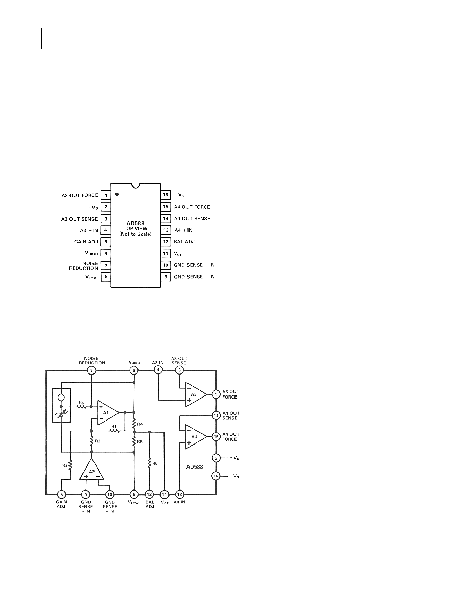
PIN CONFIGURATIONS
THEORY OF OPERATION
The AD588 consists of a buried Zener diode reference, amplifi-
ers used to provide pin programmable output ranges, and asso-
ciated thin-film resistors as shown in the block diagram of
Figure 1. The temperature compensation circuitry provides the
device with a temperature coefficient of 1.5 ppm/
°
C or less.
Figure 1. AD588 Functional Block Diagram
Amplifier A1 performs several functions. A1 primarily acts to
amplify the Zener voltage from 6.5 V to the required 10 V out-
put. In addition, A1 also provides for external adjustment of the
10 V output through Pin 5, the GAIN ADJUST. Using the bias
compensation resistor between the Zener output and the nonin-
verting input to A1, a capacitor can be added at the NOISE
REDUCTION pin (Pin 7) to form a low-pass filter and reduce
the noise contribution of the Zener to the circuit. Two matched
10 k
nominal thin-film resistors (R4 and R5) divide the 10 V
output in half. Pin V
CT
(Pin 11) provides access to the center of
the voltage span and Pin 12 (BALANCE ADJUST) can be used
for fine adjustment of this division.
Ground sensing for the circuit is provided by amplifier A2. The
noninverting input (Pin 9) senses the system ground which will
be transferred to the point on the circuit where the inverting
input (Pin 10) is connected. This may be Pin 6, 8 or 11. The
output of A2 drives Pin 8 to the appropriate voltage. Thus, if
Pin 10 is connected to Pin 8, the V
LOW
pin will be the same
voltage as the system ground. Alternatively, if Pin 10 is con-
nected to the V
CT
pin, it will be ground and Pin 6 and Pin 8 will
be +5 V and 5 V respectively.
Amplifiers A3 and A4 are internally compensated and are used
to buffer the voltages at Pins 6, 8, and 11 as well as to provide a
full Kelvin output. Thus, the AD588 has a full Kelvin capability
by providing the means to sense a system ground and provide
forced and sensed outputs referenced to that ground.
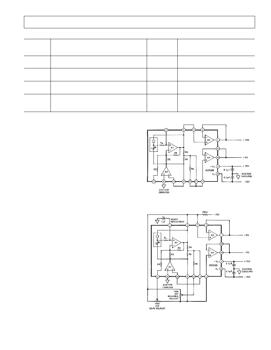
APPLYING THE AD588
The AD588 can be configured to provide +10 V and 10 V ref-
erence outputs as shown in Figures 2a and 2c respectively. It
can also be used to provide +5 V, 5 V or a
±
5 V tracking refer-
ence as shown in Figure 2b. Table I details the appropriate pin
connections for each output range. In each case, Pin 9 is con-
nected to system ground and power is applied to Pins 2 and 16.
The architecture of the AD588 provides ground sense and
uncommitted output buffer amplifiers which offer the user a
great deal of functional flexibility. The AD588 is specified and
tested in the configurations shown in Figure 2. The user may
choose to take advantage of the many other configuration op-
tions available with the AD588. However, performance in these
configurations is not guaranteed to meet the extremely stringent
data sheet specifications.
As indicated in Table I, a +5 V buffered output can be provided
using amplifier A4 in the +10 V configuration (Figure 2a). A
5 V buffered output can be provided using amplifier A3 in the
10 V configuration (Figure 2c). Specifications are not guaran-
teed for the +5 V or 5 V outputs in these configurations. Per-
formance will be similar to that specified for the +10 V or 10 V
outputs.
As indicated in Table I, unbuffered outputs are available at Pins
6, 8 and 11. Loading of these unbuffered outputs will impair
circuit performance.
Amplifiers A3 and A4 can be used interchangeably. However,
the AD588 is tested (and the specifications are guaranteed) with
the amplifiers connected as indicated in Figure 2 and Table I.
When either A3 or A4 is unused, its output force and sense pins
should be connected and the input tied to ground.
Two outputs of the same voltage may be obtained by connecting
both A3 and A4 to the appropriate unbuffered output on Pins 6,
8 or 11. Performance in these dual output configurations will
typically meet data sheet specifications.
CALIBRATION
Generally, the AD588 will meet the requirements of a precision
system without additional adjustment. Initial output voltage
error of 1 mV and output noise specs of 10
µ
V p-p allow for
AD588
REV. B
4
Table I. AD588 Connections
Connect
Buffered
Pin 10
Unbuffered
1
Output on Pins
Output
Buffered Output on Pins
Range
To Pin:
10 V
5 V
0 V
+5 V
+10 V Connections
10 V
5 V
0 V
+5 V
+10 V
+10 V
8
8
11
6
1113 & 1415
15
64 & 31
1
5 V or +5 V
11
18
11
6
813 & 1415
15
64 & 31
1
10 V
6
8
11
6
813 & 1415
15
114 & 31
1
+5 V
6
64 & 31
1
11
5 V
8
813 & 1415
15
1
"Unbuffered" outputs should not be loaded.
accuracies of 1216 bits. However, in applications where an
even greater level of accuracy is required, additional calibration
may be called for. Provision for trimming has been made
through the use of the GAIN ADJUST and BALANCE AD-
JUST pins (Pins 5 and 12 respectively).
The AD588 provides a precision 10 V span with a center tap
(V
CT
) which is used with the buffer and ground sense amplifiers
to achieve the voltage output configurations in Table I. GAIN
ADJUST and BALANCE ADJUST can be used in any of these
configurations to trim the magnitude of the span voltage and the
position of the center tap within the span. The GAIN ADJUST
should be performed first. Although the trims are not interactive
within the device, the GAIN trim will move the BALANCE trim
point as it changes the magnitude of the span.
Figure 2b shows GAIN and BALANCE trims in a +5 V and
5 V tracking configuration. A 100 k
20-turn potentiometer is
used for each trim. The potentiometer for GAIN trim is con-
nected between Pins 6 (V
HIGH
) and 8 (V
LOW
) with the wiper
connected to Pin 5 (GAIN ADJ). The potentiometer is adjusted
to produce exactly 10 V between Pins 1 and 15, the amplifier
outputs. The BALANCE potentiometer, also connected be-
tween Pins 6 and 8 with the wiper to Pin 12 (BAL ADJ), is then
adjusted to center the span from +5 V to 5 V.
Trimming in other configurations works in exactly the same
manner. When producing +10 V and +5 V, GAIN ADJ is used
to trim +10 V and BAL ADJ is used to trim +5 V. In the 10 V
and 5 V configuration, GAIN ADJ is again used to trim the
magnitude of the span, 10 V, while BAL ADJ is used to trim
the center tap, 5 V.
In single output configurations, GAIN ADJ is used to trim out-
puts utilizing the full span (+10 V or 10 V) while BAL ADJ is
used to trim outputs using half the span (+5 V or 5 V).
Input impedance on both the GAIN ADJUST and BALANCE
ADJUST pins is approximately 150 k
. The GAIN ADJUST
trim network effectively attenuates the 10 V across the trim
potentiometer by a factor of about 1500 to provide a trim range
of 3.5 mV to +7.5 mV with a resolution of approximately
550
µ
V/turn (20 turn potentiometer). The BALANCE ADJUST
trim network attenuates the trim voltage by a factor of about
1400, providing a trim range of
±
4.5 mV with resolution of
450
µ
V/turn.
Figure 2a. +10 V Output
Figure 2b. +5 V and 5 V Outputs
AD588
REV. B
5
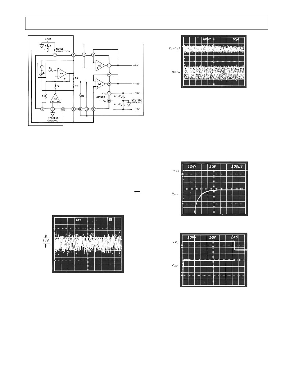
Figure 2c. 10 V Output
Trimming the AD588 introduces no additional errors over tem-
perature so precision potentiometers are not required.
For single output voltage ranges, or in cases when BALANCE
ADJUST is not required, Pin 12 should be connected to Pin 11.
If GAIN ADJUST is not required, Pin 5 should be left floating.
NOISE PERFORMANCE AND REDUCTION
The noise generated by the AD588 is typically less than 6
µ
V p-p
over the 0.1 Hz to 10 Hz band. Noise in a 1 MHz bandwidth is
approximately 600
µ
V p-p. The dominant source of this noise is
the buried Zener which contributes approximately 100 nV/
Hz
.
In comparison, the op amp's contribution is negligible. Figure 3
shows the 0. 1 Hz to 10 Hz noise of a typical AD588.
Figure 3. 0.1 Hz to 10 Hz Noise
If further noise reduction is desired, an optional capacitor may
be added between the NOISE REDUCTION pin and ground
as shown in Figure 2b. This will form a low-pass filter with the
4 k
R
B
on the output of the Zener cell. A 1
µ
F capacitor will
have a 3 dB point at 40 Hz and will reduce the high frequency
(to 1 MHz) noise to about 200
µ
V p-p. Figure 4 shows the
1 MHz noise of a typical AD588 both with and without a
1
µ
F capacitor.
Note that a second capacitor is needed in order to implement
the NOISE REDUCTION feature when using the AD588 in
the 10 V mode (Figure 2c.). The NOISE REDUCTION
capacitor is limited to 0.1
µ
F maximum in this mode.
Figure 4. Effect of 1
µ
F Noise Reduction Capacitor on
Broadband Noise
TURN-ON TIME
Upon application of power (cold start), the time required for the
output voltage to reach its final value within a specified error
band is the turn-on settling time. Two components normally as-
sociated with this are: time for active circuits to settle and time
for thermal gradients on the chip to stabilize. Figure 5 shows the
turn-on characteristics of the AD588. It shows the settling to be
about 600
µ
s. Note the absence of any thermal tails when the
horizontal scale is expanded to 2 ms/cm in Figure 5b.
a. Electrical Turn-On
b. Extended Time Scale
Figure 5. Turn-On Characteristics
Output turn-on time is modified when an external noise reduc-
tion capacitor is used. When present, this capacitor presents an
additional load to the internal Zener diode's current source, re-
sulting in a somewhat longer turn-on time. In the case of a 1
µ
F
capacitor, the initial turn-on time is approximately 60 ms (see
Figure 6).
Note: If the NOISE REDUCTION feature is used in the
±
5 V
configuration, a 39 k
resistor between Pins 6 and 2 is required
for proper start up.