 | ÐлекÑÑоннÑй компоненÑ: AN-535 | СкаÑаÑÑ:  PDF PDF  ZIP ZIP |
Äîêóìåíòàöèÿ è îïèñàíèÿ www.docs.chipfind.ru
a
AN-535
APPLICATION NOTE
One Technology Way · P.O. Box 9106 · Norwood, MA 02062-9106 · 781/329-4700 · World Wide Web Site: http://www.analog.com
Digital Input/Output Subsystems
INTRODUCTION
The DB-16 and DB-24 are 16- and 24-channel digital I/O
subsystems providing a reliable, solid state, optically
isolated interface between data acquisition boards, such
as the Analog Devices' RTI-800 series, or distributed I/O
signal conditioning subsystems such as the Analog
Devices' Model 6B50, and discrete high level I/O.
The DB-16 is a manifold card that accepts up to 16
single-channel digital input and output modules. These
solid state relay modules can be mixed and matched to
provide an interface to ac inputs, ac outputs, dc inputs
and dc outputs. Each I/O module is individually con-
trolled or sensed by the digital I/O of the data acquisition
board or the 6B50 subsystem.
The DB-24 is a manifold card that can accept up to six
4-channel (quad) digital input and output modules.
These modules can be mixed and matched as well. Each
module handles four channels of identical levels, and
the state of each input or output can be observed via the
four LEDs on each module.
The DB-16 and DB-24 share the same pinout and 50-pin
card edge connector and can be used interchangeably.
However, only the 16 channels are addressable on the
DB-16. An external +5 V dc power supply at 300 mA
maximum is required for operation.
DB-16 Digital I/O Subsystem
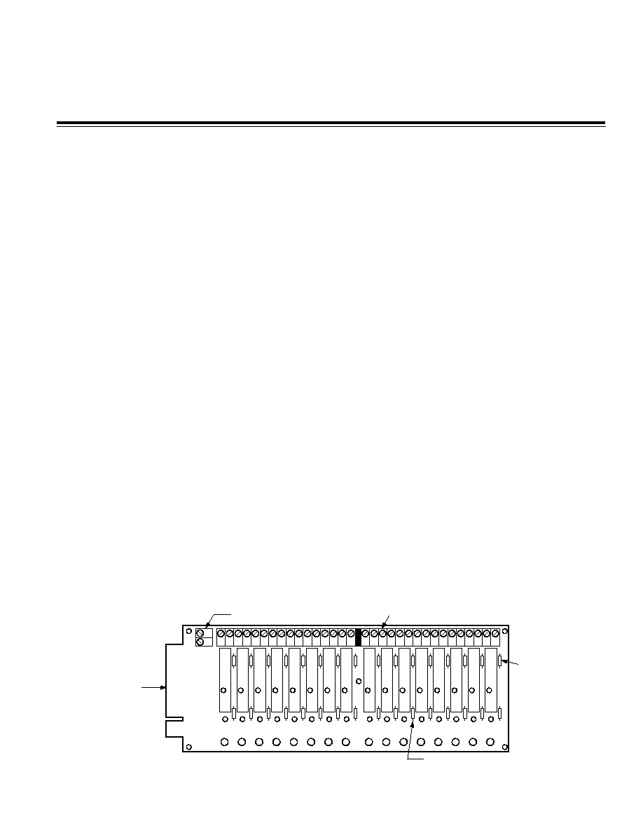
Use the DB-16 Digital I/O Backplane, shown in Figure 1,
and its associated ac and dc single-channel I/O modules
to measure and/or control high level ac and dc signals or
if isolation of the digital I/O is required.
Single-Channel Solid State Relays
The DB-16 supports the installation of up to 16 single-
channel, solid-state relay modules, which provide
2500 V peak of optical isolation. You should install the
modules in their appropriate positions in the backplane
and secure them with one screw each.
All output modules can switch up to three amps. AC out-
put modules provide zero voltage turn-on and have an
RC (resistor-capacitor) snubber network for increased
capability with inductive loads. AC and dc input mod-
ules are designed with filtering on the input and hyster-
esis for high noise rejection and transient-free "clean"
switching. They are designed so that high voltage tran-
sients on the input do not cause damage to the module.
Each module operates by negative true logic, in which a
low digital voltage turns on current to the module. Indi-
vidual LED status indicators monitor module activity
and light when the current is ACTIVE.
Each I/O module position on the DB-16 backplane has
a 5 amp, 250 V rms pico-fuse (Littelfuse
®
Part Number
251 005) protecting the module and wiring from short
circuits.
49
1
KEY
SLOT
0
1
2
3
4
5
6
7
8
9
10
11
12
13
14
15
BARRIER STRIP FOR
LOGIC SUPPLY INPUT
POWER BARRIER
STRIP
POWER LINE
FUSE, 5 AMP
PULL-UP RESISTOR
3.3k
SIGNAL CARD EDGE
CONNECTOR
Figure 1. DB-16 Digital I/O Backplane
All trademarks are the property of their respective holders.
2
AN-535
Table I lists the input and output modules available for
use with the DB-16 backplane.
Table I. Single-Channel Input/Output Module Summary
Output
Input
Type
Model
Range
Current
Current
Input
ID016
4 V16 V dc
68 mA
ID032
10 V32 V dc
34 mA
IA140A
90 V140 V ac
5 mA
90 V140 V dc
IA280A
180 V280 V dc
180 V280 V ac
5 mA
Output OD060
5 V60 V dc
3.0 A rms
OA140A
12 V140 V ac
3.5 A rms
OA280A
24 V280 V ac
3.5 A rms
Attaching Digital I/O Applications to the DB-16
Backplane
The DB-16 backplane is powered through an external
+5 V dc power supply. Applications to the DB-16 back-
plane are connected through the screw terminal barrier
strip, which contains 32 standard slot-head screw termi-
nals (screw terminals 1 and 2 are associated with chan-
nel 0 on the backplane; screw terminals 3 and 4 are
associated with channel 1 on the backplane, and so on).
Use the odd-numbered screw terminal for the high in-
put; use the even-numbered screw terminal for the low
input.
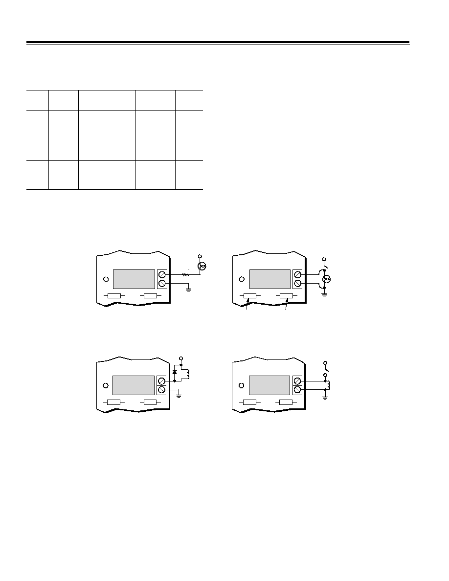
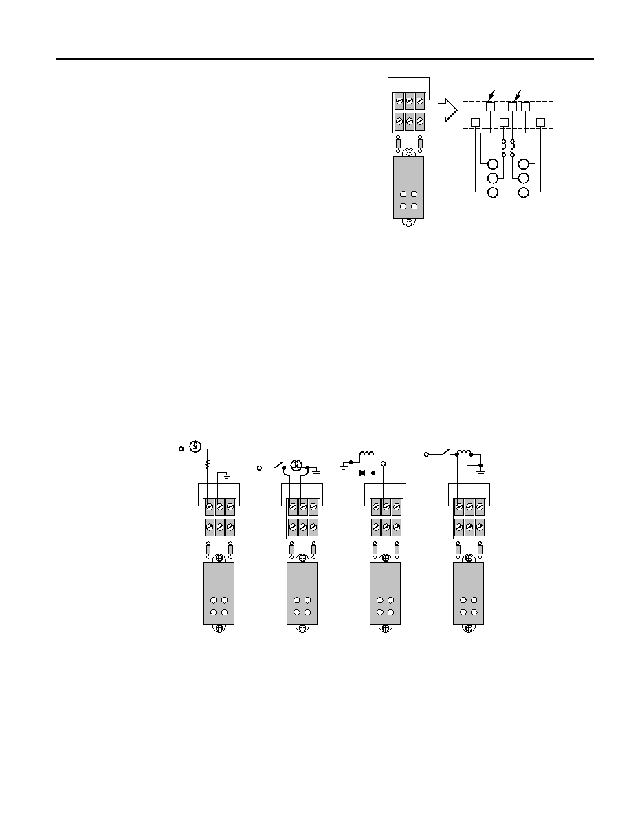
Figure 2 illustrates high level ac and dc digital wiring us-
ing input and output modules on the DB-16 backplane.
Example 2a illustrates turning a lamp on or off; example
2b illustrates monitoring whether the lamp is on or off;
example 2c illustrates turning a relay coil on and off; and
example 2d illustrates monitoring whether or not a relay
coil is energized.
INPUT MODULE
4
14
115V AC
PULL-UP
RESISTOR
SOCKETED
PICO FUSE (5A)
LED
SCREW
#29
#30
b. AC Input
OUTPUT MODULE
4
15
CURRENT
LIMIT
RESISTOR
1
115V AC
SCREW
#31
#32
LED
OUTPUT MODULE
4
13
+24V DC
2
RELAY
COIL
3
SCREW
#27
#28
LED
a. AC Output
INPUT MODULE
4
12
115V DC
LED
SCREW
#25
#26
c. DC Output
d. DC Input
NOTES:
1
SHOULD NOT EXCEED 3A.
2
USER SUPPLIED DIODE NECESSARY FOR INDUCTIVE SPIKE DAMPING.
3
RELAY COIL AMPERAGE SHOULD NOT EXCEED OUTPUT MODULE RATING.
4
MODULES ARE COLOR CODED: AC INPUT
AC OUTPUT BLACK
DC INPUT
DC OUTPUT
WHITE
RED
YELLOW
Figure 2. Typical High-Level Digital I/O Wiring Examples Using the DB-16 Backplane
3
AN-535
DB-24 Digital I/O Subsystem
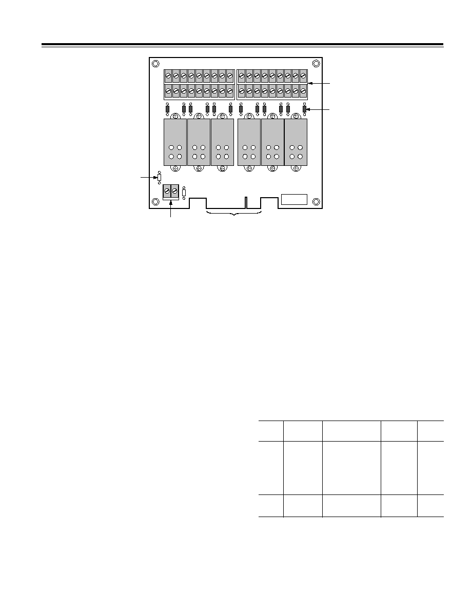
Use the DB-24 Digital I/O manifold card, shown in Figure
3, and its associated dc and ac 4-channel I/O modules to
measure and/or control high level ac and dc signals or if
isolation of the digital I/O is required.
4-Channel Solid State Relays
The DB-24 is a 24-channel I/O backplane that supports
the installation of up to six 4-channel, high-density mod-
ules to perform ac input, dc input, dc output, and dc out-
put functions. You install each module into a socketed
position on the DB-24 backplane, where each module
is held in place with two screws, provided with the
module.
All output modules are able to switch up to 3 amps. AC
output modules provide zero voltage turn-on and have
an RC snubber network for increased capability with in-
ductive loads. AC and dc input modules are designed
with filtering on the input and hysteresis for high noise
rejection and transient free "clean" switching. They are
designed so that high voltage transients on the input
will not cause damage to the module. Optical isolation
for the ac and dc input and output module is rated at
4000 V rms input-to-output.
Each module is color-coded by function and the model
number is clearly marked on the module itself. The
channel numbers associated with the module are
printed below the module on the panel and spaces are
1
3
2
4
1
3
2
4
1
3
2
4
1
3
2
4
1
3
2
4
1
3
2
4
TO DIGITAL I/O
CONNECTOR
+5V AND
GND
KEY
SLOT
49
1
J1
25
23
03
47
811
1215
1619
2023
FUSE
1A
FUSE
5A
BARRIER
STRIP
1
C
3
5
C
7
9
C 11
2
C
4
6
C
8 10 C 12
13 C 15 17 C 19 21 C 23
14 C 16 18 C 20 22 C 24
Figure 3. DB-24 Digital I/O Backplane
provided to apply colored stick-on dots (supplied) to
match the color coding of the modules (yellow = ac in-
put, black = ac output, white = dc input, and red = dc
output). Note that the four channels corresponding to
one quad module must be configured with either all in-
put channels or all output channels.
Each module on the DB-24 Digital I/O Backplane oper-
ates by negative true logic, in which a low digital voltage
turns on current to the module. Four LEDs on each mod-
ule indicate the status of the I/O channels (the LED lights
when current is turned on).
Each I/O module position has two 5 amp, 250 V rms pico-
fuses protecting the module and wiring from short cir-
cuits. Table II lists the input and output 4-channel
modules available for use with the DB-24 backplane.
Table II. Quad Input/Output Module Summary
Output
Input
Type
Model
Range
Current
Current
Input
ID16FQ
4 V32 V dc
68 mA
ID32Q
10 V60 V dc
34 mA
IA120QA
90 V140 V ac
90 V140 V dc
5 mA
IA240QA
180 V280 V dc
180 V280 V ac
5 mA
Output
OA240QA
24 V280 V ac
3.5 A rms
OD60Q
3 V60 V ac
3.5 A rms
4
AN-535
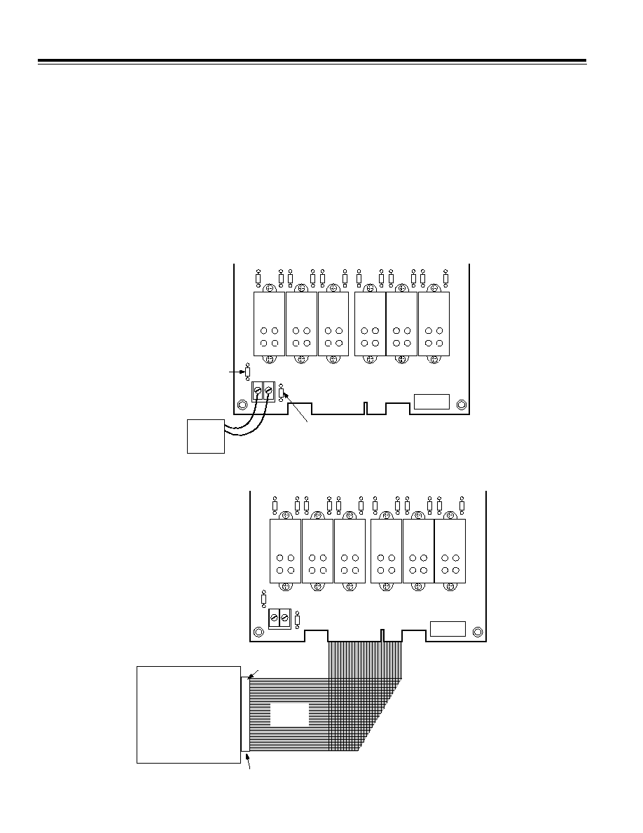
Powering the DB-24 Backplane
You can power the DB-24 Digital I/O Backplane internally
for some boards, or you can use an external +5 V power
supply. Before you attach the DB-24 backplane to the
board, you must configure it for internal or external
power.
To configure the DB-24 for internal power, remove the
socketed 1 amp fuse from the left of the +5 V dc and
GND screw terminals. Install this fuse in the socketed
position to the right of the +5 V dc and GND screw termi-
nals on the DB-24 backplane.
To configure the DB-24 backplane for external power,
ensure that the socketed 1 amp fuse is installed to the
left of the +5 V dc and GND screw terminals. Refer to
Figure 4.
Attaching the DB-24 Digital I/O Backplane
To attach the DB-24 backplane to a data acquisition or
6B50 board, use a 50-pin cable, such as the AC1585-9
cable or the CAB-03 cable (available from Analog
Devices). Attach one end of the cable to the digital I/O
connector on the board and attach the other end of the
cable to the digital I/O connector (J1) on the DB-24 back-
plane. Make sure that Pin 1 on the cable corresponds to
Pin 1 on the connector. Refer to Figure 5.
1
3
2
4
1
3
2
4
1
3
2
4
1
3
2
4
1
3
2
4
1
3
2
4
INSTALL 1A FUSE
FOR INTERNAL POWER
KEY
SLOT
49
1
J1
25
23
03
47
811
1215
1619
2023
INSTALL 1A FUSE
FOR EXTERNAL POWER
+5V
EXTERNAL
POWER
SUPPLY
1
3
2
4
1
3
2
4
1
3
2
4
Figure 4. Positioning Fuse for Internal or External Power on the DB-24 Backplane
BOARD
J1 CONNECTOR
PIN 1
1
3
2
4
1
3
2
4
1
3
2
4
DB-24
BACKPLANE
PIN 1
CAB-03 OR
AC1585-9
CABLE
1
3
2
4
1
3
2
4
1
3
2
4
1
3
2
4
1
3
2
4
1
3
2
4
Figure 5. Attaching the DB-24 Digital I/O Backplane
5
AN-535
Attaching Digital I/O Applications to the DB-24 I/O
Backplane
Use the DB-24 Digital I/O Backplane for high level ac or
dc signals. Connect applications to the backplane
through the barrier strip. The barrier strip contains stan-
dard slot-head screw terminals, six screws for each
4-channel (quad) I/O module. Use 22-14 AWG twisted-
pair wire, and strip the wire back approximately
0.25-inch (6.3 mm). Four consecutive input or output ap-
plications are attached to a single quad module, with
two channels sharing the same common in the module.
The two common connections for each module are con-
nected to one another on the DB-24 backplane. There-
fore, each of the four individual channels on the module
can use either of its two common connections. Since the
commons are connected, you must make sure that all of
the applications attached to a 4-channel module share
the same common voltage reference. If two applications
use different common voltage references, the applica-
tions must be attached to two different modules. Figure
6 illustrates how the channels and their commons are
connected.
1
3
2
4
03
1
C
3
2
C
4
1
2
3
8
9
10
I/O
CHANNEL COMMON
2
C
4
1
C
3
Figure 6. DB-24 Backplane Common Connections
Figure 7 illustrates high level ac and dc digital wiring us-
ing input and output modules on the DB-24 backplane.
Example 7a illustrates turning a lamp on and off, and
example 7b illustrates monitoring whether the lamp is
on or off. Example 7c illustrates turning a relay coil on
and off, and example 7d illustrates monitoring whether
or not the relay coil is being energized.
NOTE:
The channels on the screw terminals on the DB-24 back-
plane are labeled from 124, while the channels for the
I/O modules are labeled 023. Keep this distinction in
mind when installing your field wiring applications.
1
3
2
4
03
1
C
3
2
C
4
115V AC
CURRENT
LIMIT
RESISTOR
1
115V AC
+24V DC
2
RELAY
COIL
3
NOTES:
1
SHOULD NOT EXCEED 3A.
2
USER SUPPLIED DIODE NECESSARY FOR INDUCTIVE SPIKE DAMPING.
3
RELAY COIL AMPERAGE SHOULD NOT EXCEED OUTPUT MODULE RATING.
4
MODULES ARE COLOR CODED: AC INPUT
AC OUTPUT BLACK
DC INPUT
DC OUTPUT
WHITE
RED
YELLOW
a. AC Output
b. AC Input
c. DC Output
d. DC Input
1
3
2
4
03
1
C
3
2
C
4
1
3
2
4
03
1
C
3
2
C
4
1
3
2
4
03
1
C
3
2
C
4
I
L
115V DC
Figure 7. Typical High Level Digital I/O Wiring Using the DB-24 and 4-Channel Solid State Relay Modules