Äîêóìåíòàöèÿ è îïèñàíèÿ www.docs.chipfind.ru
REV. 0
Information furnished by Analog Devices is believed to be accurate and
reliable. However, no responsibility is assumed by Analog Devices for its
use, nor for any infringements of patents or other rights of third parties
which may result from its use. No license is granted by implication or
otherwise under any patent or patent rights of Analog Devices.
a
SSM2005
One Technology Way, P.O. Box 9106, Norwood, MA 02062-9106, U.S.A.
Tel: 781/329-4700
World Wide Web Site: http://www.analog.com
Fax: 781/326-8703
© Analog Devices, Inc., 1999
®
Decoder
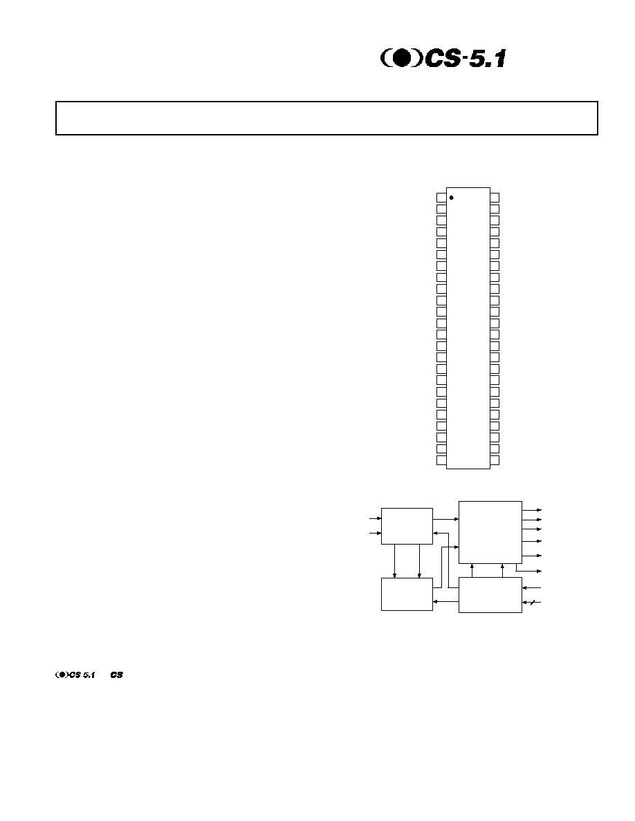
5.1-Channel Soundfield Generator
FEATURES
Generates 5.1-Channel Soundfield from All Stereo Sources
No Pre-Encoding Required
Excellent Decoding of Pre-Encoded Sources
4- or 5-Speaker Operation
Subwoofer Output
Full Bandwidth on All Channels
Optimized Modes for Video and Music
Excellent Surround Image at All Positions
Independent Left and Right Surround Steering
No Surround Channel Delay Required
Built-In White Noise Generator
APPLICATIONS
Home Theater Receivers
VCD/DVD Players
Auto Sound Receivers and Amplifiers
Surround Sound Decoders
Karaoke
Computer Audio Boards
Video Games
STEERING
CONTROL
GENERATOR
LEFT
RIGHT
INPUTS
RIGHT
SURROUND
LEFT
SURROUND
CENTER
RIGHT
LEFT
RESET
SERIAL BUS
OUTPUTS
L+R FOR
SUBWOOFER
STEERING MATRIX
AND OUTPUT
AMPLIFIERS
ANALOG
SIGNAL
PROCESSING
MODE CONTROL
LOGIC AND NOISE
GENERATOR
Figure 1. Simplified Block Diagram
PIN CONFIGURATIONS
48-Lead SSOP
(RS Suffix)
TOP VIEW
(Not to Scale)
48
47
46
45
44
43
42
41
40
39
38
37
36
35
34
33
32
31
30
29
28
27
26
25
1
2
3
4
5
6
7
8
9
10
11
12
13
14
15
16
17
18
19
20
21
22
23
24
SSM2005
CENTER OUT
R FILTER IN
R FILTER OUT
L FILTER IN
L FILTER OUT
L OUT
L OUT A
L IN
R OUT
R OUT A
R IN
V
EE
ACOM AUDIO GND
GND
V
CC
(L+R) OUT
(LR) OUT
(LR) HIGH IN
(LR) LOW IN
R HIGH BAND DET.
L HIGH BAND DET.
HIGH BAND DET. OUT
R LOW BAND DET.
L LOW BAND DET.
LOW BAND DET. OUT
LF OUT
RF OUT
LS OUT
RS OUT
NOISE IN
NOISE OUT
LOAD
RESET
DATA IN
V
CC
ACOM AUDIO GND
GND
V
EE
WRITE
CLOCK IN
FRONT/REAR TC FILTER
LOW BAND TC FILTER
HIGH BAND TC FILTER
FRONT/REAR DET.
FRONT/REAR (LR) DET.
FRONT/REAR (L+R) DET.
AUTOBALANCE LOCKOUT
AUTOBALANCE TC
GENERAL DESCRIPTION
The SSM2005 Circle Surround
®
decoder produces true 5.1-channel
surround soundfield from any stereo source, including VCD, DVD,
VCR, CD and FM stereo broadcasts. The SSM2005 is also compat-
ible with encoded sources, such as Dolby ProLogic
®
and Circle
Surround
encoded movies and music. External delays and noise
reduction processors are not required for the surround channels.
Circle Surround encoded stereo signals will produce a full 360º
soundfield when played through the SSM2005. Recording engi-
neers can encode sounds to any of the five speakers surrounding
the listener. Left Front, Right Front, Center, and differentiated
Left and Right surround channels are generated, providing a realis-
tic ambiance effect with either 4- or 5-speaker configurations.
The SSM2005 is available from Analog Devices, subject to the
License and Royalty requirements as described on the following
page of the data sheet.
and are registered trademarks of SRS Labs, Inc. and ValenceTechnology Ltd.
Circle Surround is a registered trademark of SRS Labs, Inc. and Valence Technology Ltd.
Dolby ProLogic
is a registered trademark of Dolby Laboratories Licensing Corporation, San Francisco, California.
Circle Surround technology is protected under one or more of the following U.S. Patents and corresponding patents
worldwide: 5,319,713; 5,333,201; 5,638,452; 5,771,295.

2
REV. 0
SSM2005SPECIFICATIONS
ELECTRICAL CHARACTERISTICS
Parameter
Symbol
Conditions
Min
Typ
Max
Units
INPUT CHARACTERISTICS
Level
1
V
L
,
V
R
Z
SOURCE
< 10
0
dBd
Input Impedance
Z
IN
L and R Inputs
10
k
OUTPUT CHARACTERISTICS
Level
Left Front
L
T
= 0 dBd, R
T
= Off
0
dBd
Right Front
R
T
= 0 dBd, L
T
= Off
0
dBd
Center
L
T
= R
T
= 0 dBd, In Phase,
Video Mode
+6
dBd
Left Rear, Right Rear
L
T
= R
T
= 0 dBd, Out of Phase
+3
dBd
Channel Separation
Left Front and Right Front / Center
L
T
= R
T
, In Phase, Video Mode
30
dBd
Left Rear and Right Rear / Center
L
T
= R
T
, Out of Phase
40
dBd
Left Rear, Left Front
L
T
= R
T
, Out of Phase
30
dBd
Left Rear, Right Rear
L
T
= R
T
, Out of Phase
30
dBd
Output Impedance
Z
OUT
10
DYNAMIC PERFORMANCE
Total Harmonic Distortion + Noise
THD+N
All Channels
0.04
%
Signal-to-Noise Ratio
SNR
88
dB
Dynamic Range, Output
DR
Noise Floor to 1% THD
100
dB
Headroom
HR
All Channels
12
dB
NOISE GENERATOR
Output Level
2
Noise Mode On, A-Weighted
10
dBd
Matching
All Channels
0.5
1.5
dB
AUTOBALANCE
Capture Range
| V
H
| |V
L
|
±
4
dB
Capture Time
V
L
= V
R
> 10 dBd,
|V
LEFT
V
RIGHT
| < 3 dB
5
s
CONTROL LOGIC
Logic Thresholds
Logic Levels Referenced to ACOM
High (1)
2.4
V
Low (0)
0.8
V
Input Current
1
µ
A
Timing Characteristics
See Timing Diagrams
POWER SUPPLIES
Operating Voltage Range
3
V
S
Single Supply
+10
+12
V
+V
S
,
V
S
Dual Supply
±
5
±
6
V
Current
I
S
V
L
= V
R
= ACOM, V
S
= 12 V
18
30
mA
NOTES
1
0 dBd = 300 mV
rms
.
2
With filter shown in Figure 8.
3
Specifications apply for V
S
=
±
6 V.
Specifications subject to change without notice.
(V
S
=
±
6.0 V, T
A
= 25 C, f = 2 kHz, Modes: Video, 5-2-5, Center On, Sound Spread Off,
Autobalance Off, Noise Off)
The CIRCLE SURROUND
®
TECHNOLOGY rights incorporated in the SSM2005 are owned by SRS Labs, Inc. and by Valence Technology Ltd., and licensed
to Analog Devices, Inc.
Users of any SSM2005 Circle Surround decoder must first sign a free use license to purchase OEM quantities for consumer electronics applications which
may be granted upon submission of a preproduction sample to, and the satisfactory passing of performance verification tests performed by SRS Labs, Inc.
or Valence Technology Ltd. SRS Labs, Inc. and Valence Technology Ltd. reserve the right to decline a use license for any submission that does not pass
performance specifications or is not in the consumer electronics classification.
All equipment manufactured using any SSM2005 Circle Surround decoder must carry the Circle Surround logo on the front panel in a manner approved
in writing by SRS Labs, Inc. or Valence Technology Ltd. If the Circle Surround logo is printed in users manuals, service manuals or advertisements, it
must appear in a form approved in writing by SRS Labs, Inc. or Valence Technology Ltd. The rear panel of Circle Surround products, users manuals,
service manuals, and all advertisements must all carry the Circle Surround legend as specified in the Circle Surround trademark manual published by SRS
Labs, Inc. and Valence Technology Ltd.
LICENSING INFORMATION
SSM2005
3
REV. 0
ABSOLUTE MAXIMUM RATINGS*
Supply Voltage, V
S
. . . . . . . . . . . . . . . . . . . . . .
±
8 V or +16 V
Logic Inputs . . . . . . . . . . . . . . . . . . . . . . . . . . . . . . . . . . . . V
S
Storage Temperature Range . . . . . . . . . . . . 65
°
C to +150
°
C
Operating Temperature Range . . . . . . . . . . . 20
°
C to +70
°
C
Junction Temperature Range . . . . . . . . . . . . . . . . . . . .+150
°
C
Lead Temperature Range (Soldering, 60 sec) . . . . . . . +300
°
C
*Stresses above those listed under Absolute Maximum Ratings may cause perma-
nent damage to the device. This is a stress rating only; functional operation of the
device at these or any other conditions above those listed in the operational sections
of this specification is not implied. Exposure to absolute maximum rating condi-
tions for extended periods may affect device reliability.
Package Type
JA
1
JC
Units
48-Lead SSOP (RS)
100
50
°
C/W
NOTE
1
JA
is specified for worst case conditions.
CAUTION
ESD (electrostatic discharge) sensitive device. Electrostatic charges as high as 4000 V readily
accumulate on the human body and test equipment and can discharge without detection.
Although the SSM2005 features proprietary ESD protection circuitry, permanent damage may
occur on devices subjected to high energy electrostatic discharges. Therefore, proper ESD
precautions are recommended to avoid performance degradation or loss of functionality.
WARNING!
ESD SENSITIVE DEVICE
ORDERING GUIDE
Temperature
Package
Package
Model
Range
Description
Option
SSM2005RS-Reel
20
°
C to +70
°
C
48-Lead SSOP
RS-48
SSM2005
4
REV. 0
FREQUENCY Hz
10
1
0.01
20
20k
100
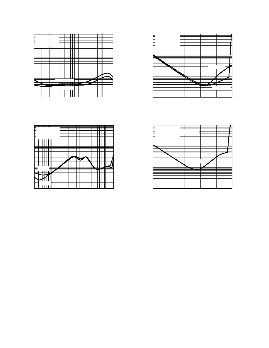
THD + N %
1k
0.1
10k
CENTER OUT
LF, RF OUT
V
SY
= ±6V
V
IN
= 300mV
rms
R
L
= 100k
Figure 2. THD + N vs. Frequency; Front Channels
RS OUT
FREQUENCY Hz
10
1
0.01
20
20k
100
THD + N %
1k
0.1
10k
V
SY
= ±6V
V
IN
= 300mV
rms
R
L
= 100k
LS OUT
Figure 3. THD + N vs. Frequency; Surround Channels
AMPLITUDE dBr A
10
1
0.01
35
15
25
THD + N %
0.1
15
5
5
V
SY
= ±6V
V
IN
= 1kHz
R
L
= 100k
0dBr = 300mV
rms
LF, RF OUT
CENTER OUT
Figure 4. THD + N vs. Amplitude; Front Channels
FREQUENCY dBr A
10
1
0.01
35
15
25
THD + N %
0.1
15
5
5
V
SY
= ±6V
L
T
= R
T
= 1kHz; OUT OF PHASE
R
L
= 100k
0dBr = 300mV
rms
LS, RS OUT
Figure 5. THD + N vs. Frequency; Surround Channels
Typical Performance Characteristics
SSM2005
5
REV. 0
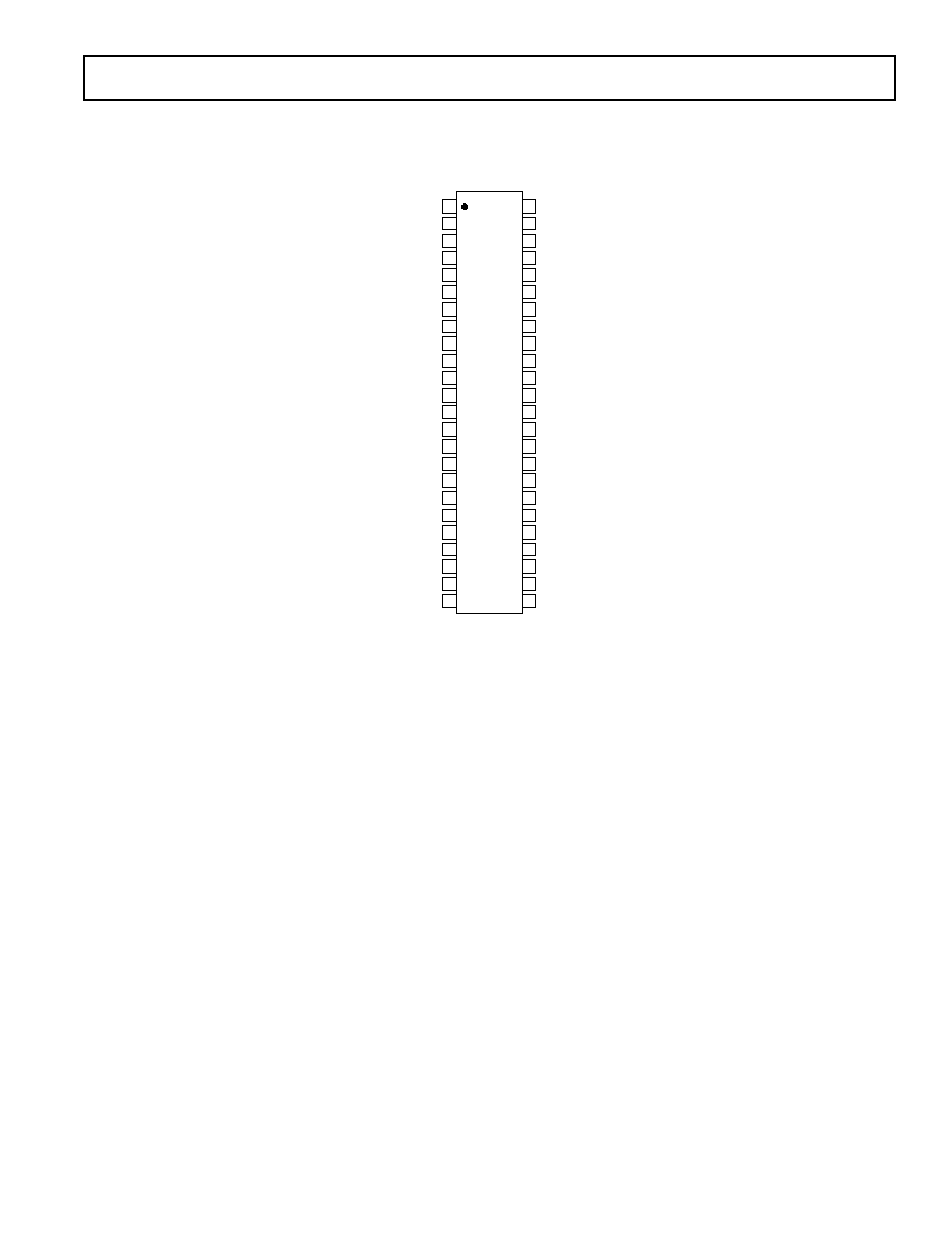
PIN CONFIGURATIONS
48-Lead SSOP
(RS Suffix)
TOP VIEW
(Not to Scale)
48
47
46
45
44
43
42
41
40
39
38
37
36
35
34
33
32
31
30
29
28
27
26
25
1
2
3
4
5
6
7
8
9
10
11
12
13
14
15
16
17
18
19
20
21
22
23
24
SSM2005
CENTER OUT
R FILTER IN
R FILTER OUT
L FILTER IN
L FILTER OUT
L OUT
L OUT A
L IN
R OUT
R OUT A
R IN
V
EE
ACOM AUDIO GND
GND
V
CC
(L+R) OUT
(LR) OUT
(LR) HIGH IN
(LR) LOW IN
R HIGH BAND DET.
L HIGH BAND DET.
HIGH BAND DET. OUT
R LOW BAND DET.
L LOW BAND DET.
LOW BAND DET. OUT
LF OUT
RF OUT
LS OUT
RS OUT
NOISE IN
NOISE OUT
LOAD
RESET
DATA IN
V
CC
ACOM AUDIO GND
GND
V
EE
WRITE
CLOCK IN
FRONT/REAR TC FILTER
LOW BAND TC FILTER
HIGH BAND TC FILTER
FRONT/REAR DET.
FRONT/REAR (LR) DET.
FRONT/REAR (L+R) DET.
AUTOBALANCE LOCKOUT
AUTOBALANCE TC
SSM2005
6
REV. 0
PIN FUNCTION DESCRIPTION
Pin #
Name
Connected to / Function:
1
R Filter In
3-Pole Active Low-Pass Filter Output; used for Center Cancelling Correction
2
R Filter Out
3-Pole Active Low-Pass Filter Input
3
L Filter In
3-Pole Active Low-Pass Filter Output; used for Center Cancelling Correction
4
L Filter Out
3-Pole Active Low-Pass Filter Input
5
L Out
Connect to Pin 6
6
L Out A
Connect to Pin 5
7
L In
Left Stereo Source Line Input; Should be 0 dBd (300 mV rms)
8
R Out
Connect to Pin 9
9
R Out A
Connect to Pin 8
10
R In
Right Stereo Source Line Input; Should be 0 dBd (300 mV rms)
11
V
EE
Negative Supply
12
ACOM Audio GND
Audio Ground
13
GND
Power Ground
14
V
CC
Positive Supply
15
(L+R) Out
RC to Front/Rear Detector Input
16
(LR) Out
RC to Front/Rear Detector Input and Input of Crossover
17
(LR) High In
Output of High-Pass Crossover
18
(LR) Low In
Output of Low-Pass Crossover
19
R High Band Det.
RC Network Fed by Right Stereo Source Line Input
20
L High Band Det.
RC Network Fed by Left Stereo Source Line Input
21
High Band Det. Out
Capacitor to ACOM; Controls Rear High Frequency Output Steering
22
R Low Band Det.
Right Input, used for Autobalance and Low Band Steering
23
L Low Band Det.
Left Input, used for Autobalance and Low Band Steering
24
Low Band Det. Out
Capacitor to ACOM; Controls Left-to-Right Output Steering
25
Autobalance TC
RC Network to ACOM
26
Autobalance Lockout
RC Network to ACOM
27
Front/Rear (L+R) Det.
RC Network Fed by (L+R) Out (Pin 15)
28
Front/Rear (LR) Det.
RC Network Fed by (L-R) Out (Pin 16)
29
Front/Rear Det.
Capacitor to ACOM; Controls Front-to-Back Output Steering
30
High Band TC Filter
RC Network to ACOM
31
Low Band TC Filter
RC Network to ACOM
32
Front/Rear TC Filter
RC Network to ACOM
33
Clock In
Clock from Serial Bus
34
WRITE
Chip Select from Serial Bus
35
V
EE
Negative Supply
36
GND
Power Ground
37
ACOM Audio GND
Audio Ground
38
V
CC
Positive supply
39
Data In
Data from Serial Bus
40
Reset
Reset from Serial Bus
41
LOAD
Load from Serial Bus
42
Noise Out
Connect to RC Filter; White Noise Output
43
Noise In
Connect to RC Filter Output; Filtered White Noise
44
RS Out
Connect to Right Surround (Rear) Amplifier Input
45
LS Out
Connect to Left Surround (Rear) Amplifier Input
46
RF Out
Connect to Right Front Amplifier Input
47
LF Out
Connect to Left Front Amplifier Input
48
Center Out
Connect to Center Amplifier Input

SSM2005
7
REV. 0
Table I. Abbreviations and Notations Used in the Text
L
Left
R
Right
L
T
Surround Encoded Left Input
R
T
Surround Encoded Right Input
LF
Left Front Output
RF
Right Front Output
LS
Left Surround Output
RS
Right Surround Output
C
Center Output
dBd
0 dBd = 300 mV rms
ACOM
Quality Audio Ground
VCA
Voltage Controlled Amplifier
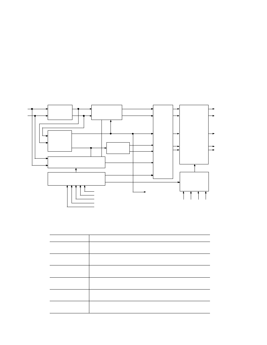
SIMPLIFIED THEORY OF OPERATION
General
The SSM2005 Circle Surround decoder processes stereo input
signals, and outputs 5 channels of surround sound, plus an L+R
output for a subwoofer low-pass filter. The SSM2005 provides
signal processing, steering control, input autobalance, and a digital
interface for mode control. This device uses analog circuits such as
amplifiers, rms detectors, VCAs and digital logic to carry out the
circle surround algorithm in real time. No artificial reverberation
or delay effects are used, preserving the natural sound of the
original stereo recording.
The SSM2005 can decode any existing media including CD,
VCD, DVD, cassette tapes, VHS, FM radio and television stereo
broadcasts. For convenience in balancing the system, an on-chip
digital noise generator is available. The net result is outstanding
5.1 channel surround sound from all stereo sources, which re-
veals the hidden ambiance already contained in existing music
and cinematic recordings. The listening experience is greatly
enhanced and made more enjoyable when compared to ordinary
stereo. In the following description, please refer to Figure 6.
Input Signal Processing
Stereo inputs L and R are fed to both the Steering Control
Generator, and the Autobalance circuitry. The balanced signals
are passed through the Center Channel Cancel circuitry to the
Channel Steering VCAs.
The autobalance output signals also feed the Precision Sum and
Difference Amplifiers. The sum (L+R) and difference (LR)
signals form the basis for the center and surround channels,
respectively. The center channel signal is fed to the center chan-
nel cancel circuitry, and to the channel steering VCAs. The
surround channel signal is separated by an external Crossover
Network into the Surround High and Surround Low bands and
fed to the channel steering VCAs.
Steering Control Generator
The purpose of the steering control generator is to analyze the dy-
namic characteristics of music, dialog, or special effects, using pro-
prietary high speed analog computing circuits. Control voltages for
all VCAs are then computed, and the soundfield expansion per-
formed in accordance with the circle surround decoding algorithm.
The control signals depend upon the SSM2005 modes selected, and
will differ for video mode vs. music mode, 5.2.5 mode vs. 4.2.4
mode, etc.
Channel Steering VCAs
Command signals from the steering control generator are fed to
the channel steering VCAs, which control the amplitude of the
five output channels. High performance, low distortion VCAs
with typically 12 dBd headroom are used for all channels.
Output Amplifier
The Output Amplifiers receive signals from the VCAs and the
internal Noise Generator. Each amplifier has a multiplexer switch
which will enable it to output a white noise waveform under
control of the Serial Bus. This simplifies balancing of the listening
system. The output amplifiers provide load drive capability with
typically 12 dBd of headroom. The overall gain from L and R
inputs to Circle Surround Outputs is unity; the Noise Generator
gives an output level of 10 dBd (100 mV rms).
Mode Control Logic
The various SSM2005 modes are shown in Figure 7. There are
modes for different types of source material, such as video sound
tracks or music. Other modes include 5.2.5/4.2.4, Sound Spread,
Phantom Center mode, autobalance, and Noise Generation. Each
mode's status is stored in the Mode Control Logic, as determined
by the data sent via the serial bus. Refer to the Typical Outputs In
Various Modes section for a more detailed explanation of the vari-
ous modes.
Applying a logic low to the Reset input will override the Mode
Control Logic and put the SSM2005 into its Default mode. De-
fault modes for the device are video/5.2.5/center active/sound
spread on/autobalance on/noise off. See Figure 9 for logic timing
diagrams.
Autobalance Feature
The autobalance circuitry is activated when the SSM2005 is placed
into autobalance On Mode. In this mode, the device will adjust the
gains of its input amplifiers to balance the stereo inputs to equal
loudness. With a mono input signal, the autobalance circuitry will
typically balance L and R to within
±
0.5 dB. A 22
µ
F external ca-
pacitor connected to Pin 25 sets a 5 second averaging period for
comparing the levels between the stereo inputs.
Using autobalance will slightly degrade the maximum channel
separation from the SSM2005. The autobalance mode can be
left off without fear of degrading the soundfield, unless the
stereo input signal is expected to be off balance by more than
±
1.5 dB. Most CD, VCD and DVD player outputs are specified
to within
±
0.25 dB balance.
Noise Generator
When the noise mode is selected, the audio inputs are muted.
Noise will be available from the output of the channel determined
by the mode control logic. The noise generator uses a feedback
shift register that generates a pseudo-random digital output wave-
form with a repeat time of three seconds. This digital noise wave-
form is band-pass filtered externally to approximate white noise.
Power Supplies
The SSM2005 may be operated from regulated
±
5 V to
±
6 V
supplies that can supply 45 mA each. The recommended operating
voltage is
±
6 V, which will give a typical headroom of 12 dBd.
SSM2005
8
REV. 0
Power-Up
The SSM2005 will be in an undefined mode on power-up. Reset
should be applied to the SSM2005, or the mode control logic
should be loaded to put the device into a definite mode state.
Serial Data Control Inputs
The SSM2005 provides a simple 3- or 4-wire serial interface to
control the mode settings for the device. Data is input on the
DATA IN pin, while CLOCK IN is the serial clock. Data can be
shifted into the SSM2005 at clock rates up to 1 MHz.
STEREO
INPUTS
PRECISION
SUM AND
DIFFERENCE
AMPLIFIERS
AMPLIFIERS
CIRCLE
SURROUND
OUTPUTS
L
R
L+R = CENTER
LR = SURROUND
LEFT
RESET
CLOCK
SELECT
LOAD
SERIAL BUS
+V
GND
V ACOM
INPUT POWER
NOISE
GENERATOR
L
R
C
L
S
R
S
RIGHT
CENTER
SURROUND
HIGH BAND
SURROUND
LOW BAND
CROSSOVER
NETWORK
7X
STEERING CONTROL GENERATOR
MODE CONTROL LOGIC
DATA
AUTO BALANCE
AND MUTE
TO SUBWOOFER
FILTER
CENTER CHANNEL
CANCEL
CHANNEL
STEERING
VCAs
OUTPUT
AMPLIFIERS
Figure 6. Block Diagram
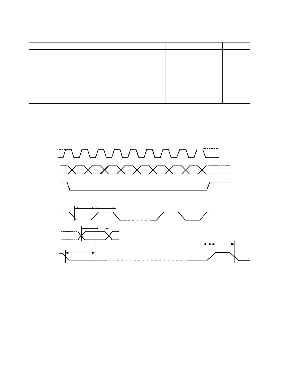
The shift register clock at CLOCK IN is enabled when the
WRITE input is low. The WRITE pin can therefore be used as a
chip select input. However, the shift register contents are not
transferred into the register banks until the rising edge of
LOAD.
For a traditional 3-wire serial interface,
WRITE and LOAD
should be tied together. Figure 7 shows the timing diagram and
minimum timing requirements for the digital interface.
To enable a data transfer, the
WRITE and LOAD inputs are
driven low. The 8-bit serial data, formatted MSB first, should
be fed to DATA IN and clocked into the shift register on the
rising edge of CLOCK IN. The new mode setting will then
activate on the rising edge of
WRITE and LOAD.
Table II. Modes List
Modes
Effect
Video
Center Channel Cancellation Active
Music
Center Cancel Cancellation Off; Center Reduced by 4 dB.
5-2-5
5-Channel Circle Surround Enabled
4-2-4
4-Channel Matrix Enabled
Center On
Center Channel Output On
Phantom Center
Center Channel Output Off; Divided and Added to LF and RF
Sound Spread On
Hard Panned Input Steered to Front and Rear Side
Sound Spread Off
Hard Panned Input Steered to Front Side Only
Autobalance On
Balances L
and R to
±
1 dB
Autobalance Off
Autobalance Disabled
Noise Off
Noise Generator Disabled
Noise On
Noise Generator On; Inputs Muted
SSM2005
9
REV. 0
Table III. Data Decoding Truth Table
MSB
LSB
Reset
D0
D1
D2
D3
D4
D5
D6
D7
Mode
1
0
0
1
X
X
X
X
X
C Noise On
1
1
0
1
X
X
X
X
X
LF Noise On
1
1
1
0
X
X
X
X
X
RF Noise On
1
0
1
0
X
X
X
X
X
LS Noise On
1
1
0
0
X
X
X
X
X
RS Noise On
1
0
0
0
X
X
X
X
X
All Mute
1
1
1
1
1
X
X
X
X
Autobalance On
1
1
1
1
0
X
X
X
X
Autobalance Off
1
1
1
1
X
1
X
X
X
Center Active
1
1
1
1
X
0
X
X
X
Phantom Center
1
1
1
1
X
X
1
X
X
Sound Spread On
1
1
1
1
X
X
0
X
X
Sound Spread Off
1
1
1
1
X
X
X
1
X
5.2.5 Mode
1
1
1
1
X
X
X
0
X
4.2.4 Mode
1
1
1
1
X
X
X
X
1
Video Mode
1
1
1
1
X
X
X
X
0
Music Mode
0
X
X
X
X
X
X
X
X
Noise Off, Autobalance On, Center Active,
Sound Spread On, 5.2.5 Mode, Video Mode
SSM2005
10
REV. 0
D7
D6
D5
D4
D3
D2
D1
D0
1
0
1
DATA
0
1
0
1
0
CLK
DATA
t
CL
CLK
1
0
t
CH
t
DS
t
DH
t
WC
t
CW
t
W3
WRITE
&
LOAD
WRITE
&
LOAD
1
0
Figure 7. Logic Timing Diagram
Table IV. Timing Description
Timing Symbol
Description
Min
Typ
Max
Units
t
CL
Input Clock Pulsewidth
50
ns
t
CH
Input Clock Pulsewidth
50
ns
t
DS
Data Setup Time
25
ns
t
DH
Data Hold Time
35
ns
t
CW
Positive CLK Edge to End of Write
25
ns
t
WC
Write to Clock Setup Time
35
ns
t
LW
End of Load Pulse to Next Write (4-Wire Mode)
20
ns
t
WL
End of Write to Start of Load (4-Wire Mode)
20
ns
t
L
Load Pulsewidth (4-Wire Mode)
250
ns
t
W3
Load Pulsewidth (3-Wire Mode)
250
ns
NOTES:
1. An idle HI (CLK-HI) or idle LO (CLK-LO) clock may be used. Data is latched on the positive edge.
2. For SPI
TM
or MICROWIRE
TM
3-wire bus operation, tie
LD to WRITE and use WRITE pulse to drive both pins. (This generates an automatic
internal
LD signal.)
3. If an idle HI clock is used, t
CW
and t
WL
are measured from the final negative transition to the idle state.
4. The first data byte selects an address (MSB HI), and subsequent MSB LO states set gain levels. Refer to the Address/Data Decoding Truth Table.
5. Data must be sent MSB first.
SPI is a trademark of Motorola, Inc.
MICROWIRE is a trademark of National Semiconductor Corporation.
SSM2005
11
REV. 0
TYPICAL OUTPUTS IN VARIOUS MODES
The SSM2005 Circle Surround decoder uses ambiance and
directional information already present in a stereo signal, and
does not require the audio signal to be encoded. The device
requires no delay generators or noise reduction. Fully differenti-
ated rear channels provide rear stereo separation for enhanced
spatial perception, a feature unique to Circle Surround.
Video mode provides the highest degree of channel separation
between the front and center speakers. Video mode cancels com-
mon center channel material from the left and right front chan-
nels. This restores a wide stereo image to matrix encoded sound
tracks, while maintaining a solid center channel for dialogue and
mono information.
The Music mode is optimized for unencoded stereo music repro-
duction, with full bandwidth on all channels. The steering for the
LF and RF channels is deactivated to prevent any stereo image
wandering. The independent two-band rear channel steering
provides excellent surround imaging, even in car audio applica-
tions. Well balanced sound is obtained everywhere within a 4- or
5-speaker setup.
The 5.2.5 mode provides the maximum channel separation to
the surround channels, and should be used with any encoded
stereo input signal. The 4.2.4 mode can be used to reduce the
dynamic steering of the surround channels, allowing the
SSM2005 to simulate a 4-channel surround sound decoder.
Sound Spread OFF allows the maximum channel separation
between the surround and front speakers. With Sound Spread
OFF, a hard panned left input signal will produce an output
only in the left front output. In Sound Spread ON mode, a hard
panned left input signal will produce equal output from the left
front and left surround outputs.
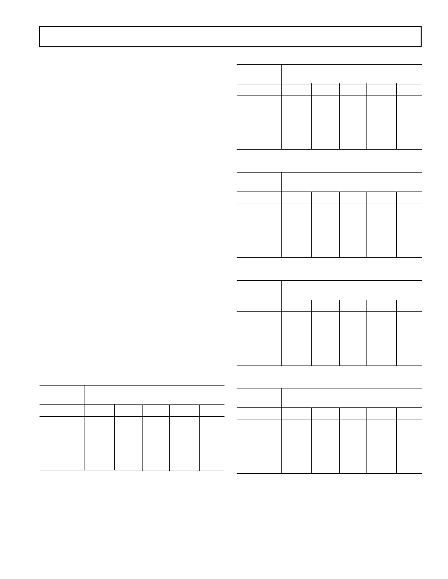
The following tables demonstrate the differences between the
modes of the SSM2005 under various input conditions. The L
T
and R
T
inputs are at 2 kHz, and are shown in terms of their
differences in magnitude (in dB) and phase (in degrees). For
example, a 0
180
°
input means L
T
is exactly equal in magni-
tude, but opposite in phase to R
T
.
Table V. Video/5.2.5/Sound Spread OFF/Center ON
Input
Output
|L
T
| |R
T
|
(dB)
dB
|LF|
|RF|
|C|
|LS|
|RS|
0 0
°
30
30
+6
40
40
0 180
°
35
35
45
+6
+6
L
T
Only
0
60
30
30
35
R
T
Only
60
0
30
35
30
6 0
°
0
15
4
25
30
6 180
°
30
36
26
0
15
Table VI. Video/5.2.5/Sound Spread ON/Center ON
Input
Output
|L
T
| |R
T
|
(dB)
dB
|LF|
|RF|
|C|
|LS|
|RS|
0 0
°
30
30
+6
40
40
0 180
°
35
35
45
+6
+6
L
T
Only
0
60
30
0
30
R
T
Only
60
0
30
30
0
6 0
°
0
15
4
0
25
6 180
°
30
36
26
0
15
Table VII. Music/5.2.5/Sound Spread ON/Center ON
Input
Output
|L
T
| |R
T
|
(dB)
dB
|LF|
|RF|
|C|
|LS|
|RS|
0 0
°
0
0
+2
40
40
0 180
°
0
0
45
+6
+6
L
T
Only
0
60
30
0
30
R
T
Only
60
0
30
30
0
6 0
°
0
6
4
0
25
6 180
°
0
6
26
0
15
Table VIII. Video/5.2.5/Sound Spread ON/Phantom Center
Input
Output
|L
T
| |R
T
|
(dB)
dB
|LF|
|RF|
|C|
|LS|
|RS|
0 0
°
+3
+3
Off
40
40
0 180
°
35
35
Off
+6
+6
L
T
Only
0
60
Off
0
30
R
T
Only
60
0
Off
30
0
6 0
°
0
15
Off
0
25
6 180
°
30
36
Off
0
15
Table IX. Video/4.2.4/Sound Spread OFF/Center ON
Input
Output
|L
T
| |R
T
|
(dB)
dB
|LF|
|RF|
|C|
|LS|
|RS|
0 0
°
30
30
+6
40
40
0 180
°
35
35
45
+6
+6
L
T
Only
0
60
30
32
32
R
T
Only
60
0
30
32
32
6 0
°
0
15
4
26
26
6 180
°
30
36
26
0
2
SSM2005
12
REV. 0
4.7M
0.01 F
5.9k
105k
48.7k
4.7nF
0.1 F
100
LEFT IN
10 F
10 F
0.1 F
100
RIGHT IN
10 F
0.1 F
6V
6V
SSM2275-A
10 F
0.1 F
40.2k
1nF
1nF
787
0.1 F
1 F
787k
909
0.1 F
100pF
SSM2275-B
10 F
0.1 F
909
0.1 F
453
453
0.1 F
0.1 F
1 F
453
453
0.1 F
1 F
L R OUT
TO SUBWOOFER FILTER
(OPTIONAL)
1 F
1k
C
OUT
LF
OUT
RF
OUT
LS
OUT
RS
OUT
0.47 F
3.82k
LOAD
RESET
DATA
1 F
33.2k
6V
6V
WRITE
CLK IN
0.1 F
0.22 F
274k
1 F
100k
0.1 F
0.22 F
274k
1 F
1 F
22 F
10k
1 F
DENOTES CONTROL
GROUND
DENOTES SIGNAL
GROUND
DENOTES CONNECTION
7.87k
+
+
+
+
+
162k
+
1 F
1k
1
2
3
4
5
6
7
8
9
10
11
12
13
14
15
16
17
18
19
20
21
22
23
24
SSM2005
48
47
46
45
44
43
42
41
40
39
38
37
36
35
34
33
32
31
30
29
28
27
26
25
787
0.01 F
0.1 F
SSM2275-B
0.01 F
5.9k
105k
48.7k
4.7nF
0.1 F
SSM2275-A
10 F
+
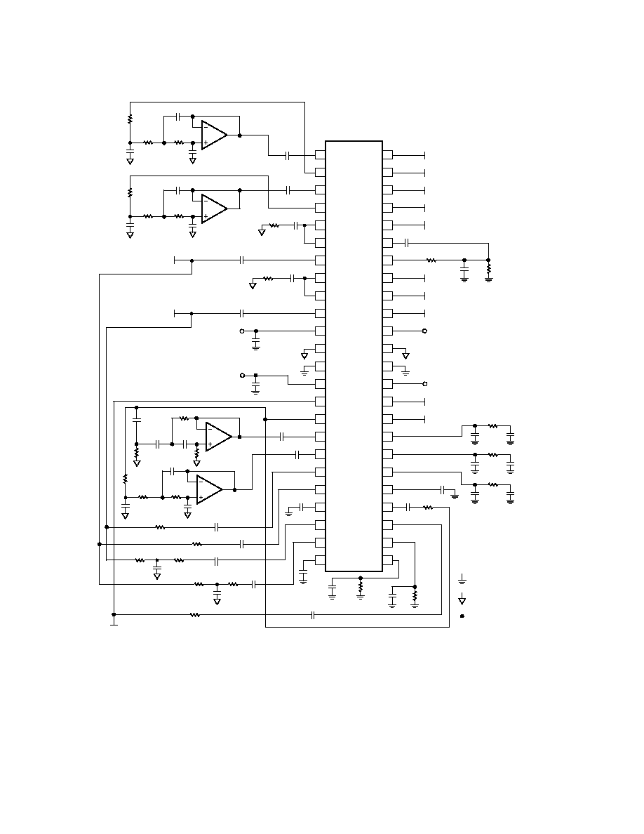
Figure 8. Typical Application Schematic
SSM2005
13
REV. 0
APPLICATION NOTES
Figure 8 shows a typical SSM2005 application schematic. The
stereo source signal is connected to the SSM2005 audio signal
inputs at Pins 7 and 10, as well as the Left/Right level detectors
at Pins 19, 20, 22, and 23. The input signal goes through the
autobalance circuitry and can be accessed at Pins 6 and 9.
A sum (L+R) and difference (LR) signal is available at Pins 15
and 16, respectively. These signals are fed into the Front/Rear
level detector at Pins 27 and 28.
The L+R signal is also fed internally to the center channel VCA
to produce the center channel output at Pin 48. In addition, the
LR signal is fed into two external filters, creating a low-band and
high-band signal with a crossover frequency of 2 kHz. The cross-
over filters are both 3
rd
order Bessel filters, providing a minimum
group delay to the surround channels. The LR high-band signal
is connected to Pin 17, and the LR low-band signal is connected
to Pin 18. These two pins provide the multiband steering to the
two surround outputs.
Low-pass filters are inserted between Pins 1 and 2, and Pins 3
and 4. These filters are used for the center-canceling circuitry,
which removes center channel information from the left front
and right front outputs. This circuitry is only active in Video
mode, providing maximum channel separation between the
center and front outputs. In an application that will only use
Music mode, these active filters can be removed and replaced
with a 1
µ
F capacitor between Pins 1 and 2, and Pins 3 and 4.
The capacitors and resistors connected to Pins 21, 24, 25, 26, 29,
30, 31 and 32 are used to create the time constants for the steer-
ing circuitry. The values shown in Figure 8 are strongly recom-
mended. Variation from these values will result in improper
operation of the Circle Surround decoder, and may result in the
assembled unit failing SRS Labs approval.
The noise generator output is at Pin 42, and the input to the noise
steering circuit is at Pin 43. The R-C network connected between
Pins 42 and 43 is used to remove dc voltage and high frequencies,
which could damage speakers. Other noise-shaping circuitry could
be used here to create noise patterns other than white, or to further
attenuate the noise output with a resistor divider.
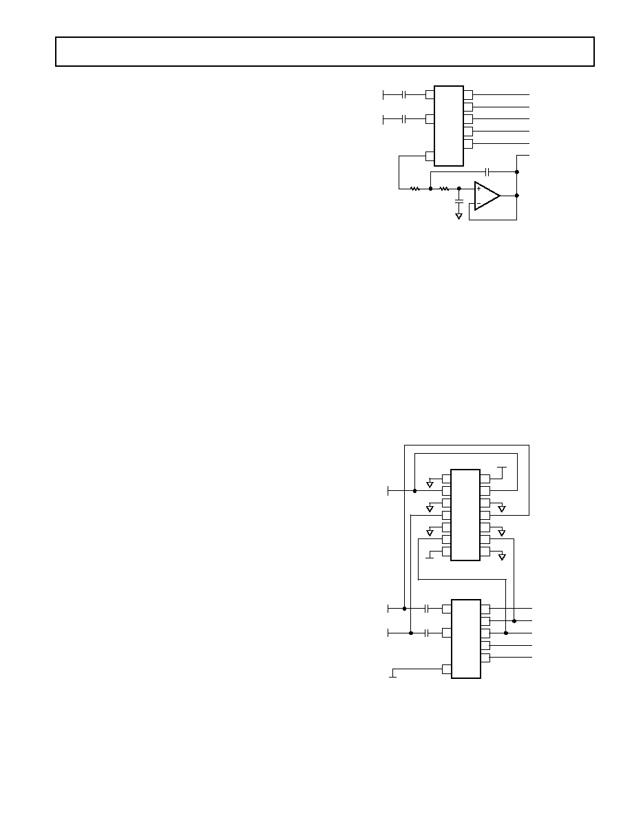
Adding a Subwoofer Output
The SSM2005 provides an output of the summed Left In and
Right In signals. This L+R signal is used to drive the center chan-
nel output, and it can also be used to provide a subwoofer chan-
nel by connecting the output from Pin 15 to a low-pass filter. The
schematic for such a configuration is shown in Figure 9.
Here, Pin 15 is connected to a 2nd order Bessel low-pass filter.
The circuit uses the SSM2275, a low noise audio op amp that
can run from the same
±
6 V that power the SSM2005. Using
the component values shown in Figure 9, the filter's cutoff
frequency is 100 Hz.
48
47
46
45
44
7
10
39
SSM2005*
LEFT IN
RIGHT IN
10 F
10 F
CENTER
L
F
R
F
L
S
R
S
OUTPUTS
*ADDITIONAL PINS
OMITTED FOR CLARITY
SSM2275
2.05k
4.23k
1 F
SUBWOOFER
0.47 F
f
C
= 100Hz
Figure 9. Adding a Subwoofer Output
Implementing a Stereo Bypass Mode
Figure 10 shows a schematic for implementing a clickless stereo
bypass around the SSM2005. The stereo bypass mode allows
the user to defeat the Circle Surround decoding and listen to
two-channel stereo from the left front and right front speakers.
The SSM2402 is a clickless dual audio single-pole single-throw
(SPST) switch. When the control voltage, V
BYP
, is low (below
+0.8 V) the switch is open, and the five channel outputs are
connected to the outputs of the SSM2005. When V
BYP
goes
high (above +2.0 V) the SSM2402 switch closes, connecting the
LF and RF outputs to Left In and Right In respectively. At the
same time, a data byte should be loaded into the SSM2005,
placing the Circle Surround decoder into Mute Mode. The data
byte required for Mute Mode can be found in Table III, and the
logic timing diagrams can be found in Figure 7.
48
47
46
45
44
7
10
39
14
13
12
11
10
9
8
1
2
3
4
5
6
7
SSM2402
+6V
6V
V
BYP
V
BYP
HIGH =
STEREO MODE
V
BYP
LOW = CIRCLE
SURROUND MODE
SSM2005*
DATA IN
LEFT IN
RIGHT IN
10 F
10 F
CENTER
L
F
R
F
L
S
R
S
OUTPUTS
*ADDITIONAL PINS
OMITTED FOR CLARITY
x DENOTES A DON'T CARE BIT
V
BYP
LOW = CS MODE
0 0 0 x x x xx
Figure 10. Implementing a Clickless Stereo Bypass Mode
SSM2005
14
REV. 0
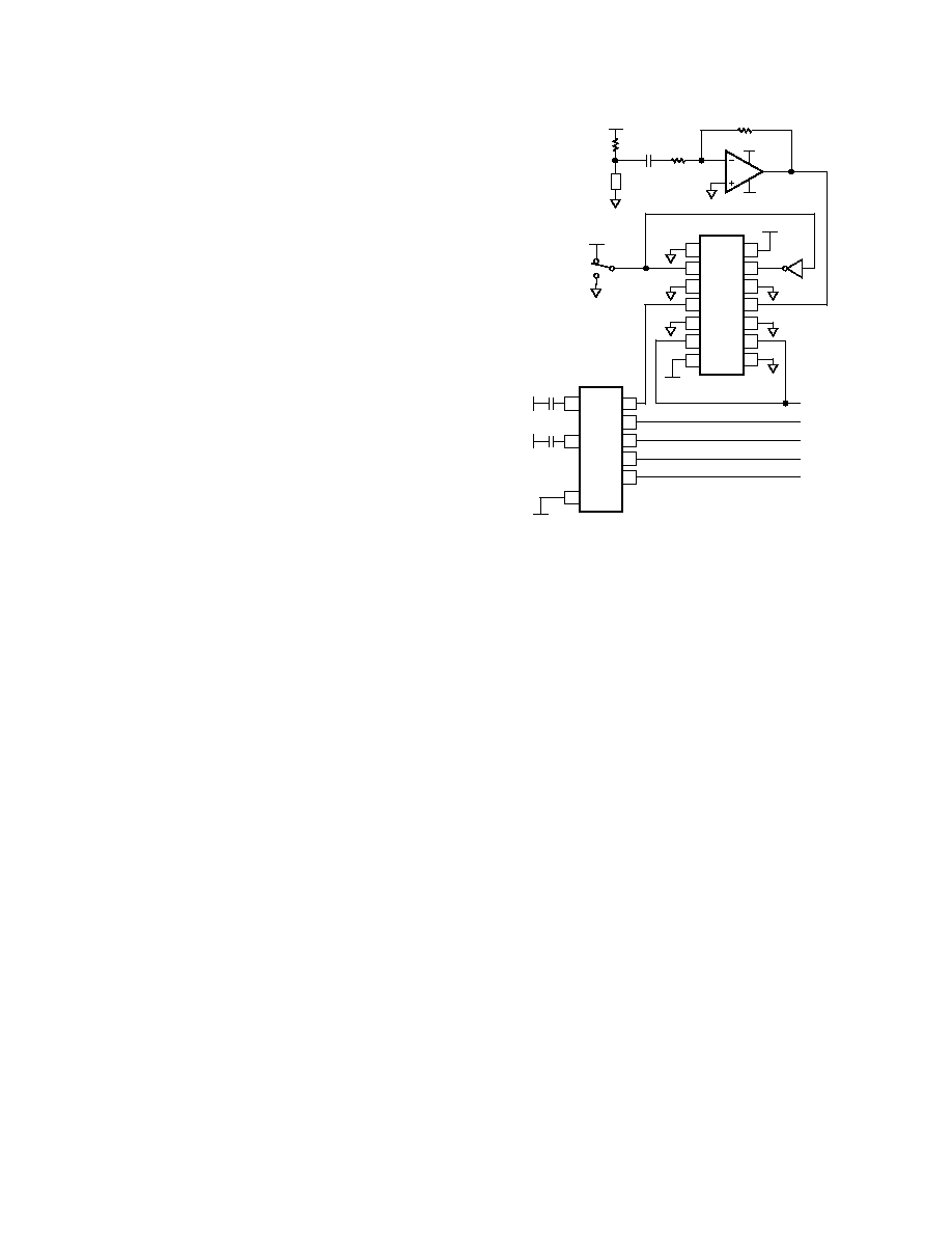
Using the SSM2005 for Karaoke
In Video mode, the SSM2005 removes centered vocal informa-
tion from the LF and RF speakers. This allows the device to be
used in Karaoke applications, where the user can sing along with
any music recording. Figure 11 shows a circuit diagram for such
an application.
The OP179 is the microphone preamplifier with a gain of +20 dB.
A 2.2 k
resistor connects the microphone to the +6 V supply rail,
providing proper biasing for an electret microphone.
The SSM2402 is used as a clickless switch, connecting the
center output to either the center out from the SSM2005 or the
microphone. In Circle Surround mode, the control voltages to
the SSM2402 connect the output from the SSM2005 to the
center output.
In Karaoke Mode, this connection is opened, and the micro-
phone is directed to the center output. At the same time, the
SSM2005 should be loaded with data byte (MSB first):
1 1 1 0 1 0 1 1. This activates the center canceling circuitry in
the SSM2005, removing centered vocal information from the
left front and right front speakers.
The overall result is the microphone output comes out of the
center speaker, with the vocals-removed music coming from the
remaining speakers.
14
13
12
11
10
9
8
1
2
3
4
5
6
7
SSM2402
+6V
6V
SSM2005*
FOR KARAOKE, LOAD DATA
BYTE: 1 1 1 0 1 0 1 1
LEFT IN
RIGHT IN
10 F
10 F
CENTER
L
F
R
F
L
S
R
S
OUTPUTS
*ADDITIONAL PINS OMITTED
FOR CLARITY
+5V
KARAOKE
MODE
CIRCLE
SURROUND
MODE
SW-2
7404
6V
OP179
+6V
0.1 F 1k
MIC
2.2k
10k
+6V
48
47
46
45
44
7
10
39
Figure 11. Using the SSM2005 for Karaoke
SSM2005
15
REV. 0
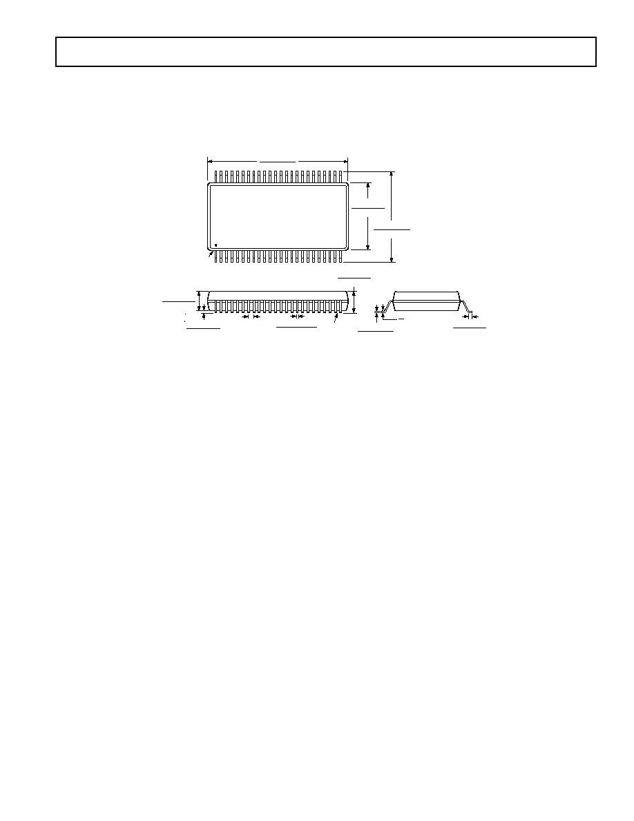
OUTLINE DIMENSIONS
Dimensions shown in inches and (mm).
48-Lead SSOP
(RS Suffix)
0.010 (0.254)
0.005 (0.127)
0.040 (1.02)
0.024 (0.61)
8
0
48
25
24
1
0.630 (16.00)
0.620 (15.75)
0.410 (10.41)
0.400 (10.16)
0.299 (7.59)
0.292 (7.42)
PIN 1
SEATING
PLANE
0.016 (0.41)
0.008 (0.20)
0.025 (0.635)
BSC
0.0135 (0.343)
0.008 (0.203)
0.110 (2.79)
0.095 (2.41)
0.092 (2.34)
0.088 (2.24)
C362887/99
PRINTED IN U.S.A.