1214-220M, R2
ADVANCED POWER TECHNOLOGY INC. RESERVES THE RIGHT TO MAKE CHANGES WITHOUT FURTHER NOTICE. TO VERIFY THE
CURRENT VERSION PLEASE CHECK OUR WEB SITE AT
WWW. ADVANCEDPOWER.COM
OR CONTACT OUR FACTORY
DIRECT.
Advanced Power Technology Inc. 3000 Oakmead Village Drive, Santa Clara, CA 95051-0808 Tel. 408 / 986-8031 Fax 408 /869-2324
Final Proof
GENERAL DESCRIPTION
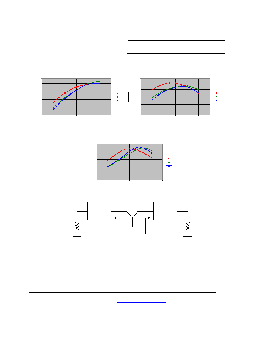
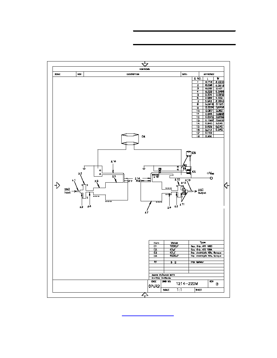
The 1214-220M is an internally matched, COMMON BASE transistor capable
of providing 220 Watts of pulsed RF output power at one hundred fifty
microseconds pulse width, ten percent duty factor across the band 1200 to 1400
MHz. This hermetically solder-sealed transistor is specifically designed for
L-Band radar applications. It utilizes gold metallization and diffused emitter
ballasting to provide high reliability and supreme ruggedness.
CASE OUTLINE
55ST, STYLE 1
ABSOLUTE MAXIMUM RATINGS
Maximum Power Dissipation @ 25
o
C 700 Watts
Maximum Voltage and Current
BVces Collector to Emitter Voltage 70 Volts
Iebo Emitter to Base Voltage 5 mA
Ic Collector Current 20 Amps
Maximum Temperatures
Storage Temperature - 65 to + 200
o
C
Operating Junction Temperature + 200
o
C
ELECTRICAL CHARACTERISTICS @ 25
O
C
SYMBOL
CHARACTERISTICS
TEST CONDITIONS
MIN
TYP
MAX
UNITS
Pout
Pg
c
Rl
VSWR
1
VSWRs
Power Out ( Note 1)
Power Gain
Collector Efficiency
Input Return loss
Load Mismatch Tolerance
Load Mismatch - Stability
Vcc=40V, Pin=40W, f = 1.2, 1.3, 1.4 GHz
Vcc=40V, Pin=40W, f = 1.2, 1.3, 1.4 GHz
Vcc=40V, Pin=40W, f = 1.2, 1.3, 1.4 GHz
Vcc=40V, Pin=40W, f = 1.2, 1.3, 1.4 GHz
Vcc=40V, Pin=40W, f = 1.2 GHz
Vcc=40V, Pin=40W, f = 1.2 GHz
220
7.4
45
9
50
290
3:1
2:1
Watts
dB
%
dB
Note 1: Pulse condition of 150
µ
sec, 10%.
BVces
Ices
Iebo
Hfe
jc
1
Collector to Emitter Breakdown
Collector to Emitter Leakage
Emitter to Base Breakdown
DC Current Gain
Thermal Resistance
Ic = 100 mA
Vce = 40 Volts
Veb = 3 Volts
Vce = 5 V, Ic = 1 A
Rated Pulse Condition
70
10
45
10
5
0.25
Volts
mA
mA
o
C/W
1214 ≠ 220M
220 Watts - 40 Volts, 150
µ
s, 10%
Radar 1200 - 1400 MHz