
2729-125
125 Watts, 36 Volts, 100µs, 10%
Radar 2700-2900 MHz
GENERAL DESCRIPTION
The 2729-125 is an internally matched, COMMON BASE bipolar transistor
capable of providing 125 Watts of pulsed RF output power at 100µs pulse
width, 10% duty factor across the 2700 to 2900 MHz band. The transistor
prematch and test fixture has been optimized through the use of Pulsed
Automated Load Pull. This hermetically solder-sealed transistor is specifically
designed for S-band radar applications. It utilizes gold metallization and emitter
ballasting to provide high reliability and supreme ruggedness.
CASE OUTLINE
55KS-1
Common Base
ABSOLUTE MAXIMUM RATINGS
Maximum Power Dissipation
Device Dissipation @ 25
∞C
1
350
W
Maximum Voltage and Current
Collector to Base Voltage (BV
ces
) 65
V
Emitter to Base Voltage (BV
ebo
) 3.0
V
Collector Current (I
c
) 15
A
Maximum Temperatures
Storage Temperature
-65 to +200
∞C
Operating Junction Temperature
+200
∞C
ELECTRICAL CHARACTERISTICS @ 25
∞C
SYMBOL CHARACTERISTICS
TEST
CONDITIONS
MIN
TYP MAX UNITS
P
out
Power Output
F=2700-2900 MHz
125
W
P
in
Power
Input
V
cc
= 36 Volts
15.7
W
P
g
Power Gain
Pulse Width = 100 µs
9.0
9.5
dB
c
Collector Efficiency
Duty Factor = 10%
45
55
%
VSWR
Load Mismatch Tolerance
1
F = 2900 MHz, P
o
= 125W
2:1
FUNCTIONAL CHARACTERISTICS @ 25
∞C
BV
ebo
Emitter to Base Breakdown
Ie = 30 mA
3.0
V
BV
ces
Collector to Emitter Breakdown Ic = 120 mA
56
65
V
h
FE
DC ≠ Current Gain
Vce = 5V, Ic = 600 mA
18
50
jc
1
Thermal Resistance
0.5
∞C/W
NOTE:
1. At rated output power and pulse conditions
Issue April 2003
Advanced Power Technology reserves the right to change, without notice, the specifications and information
contained herein. Visit our web site at
www.advancedpower.com
or contact our factory direct.
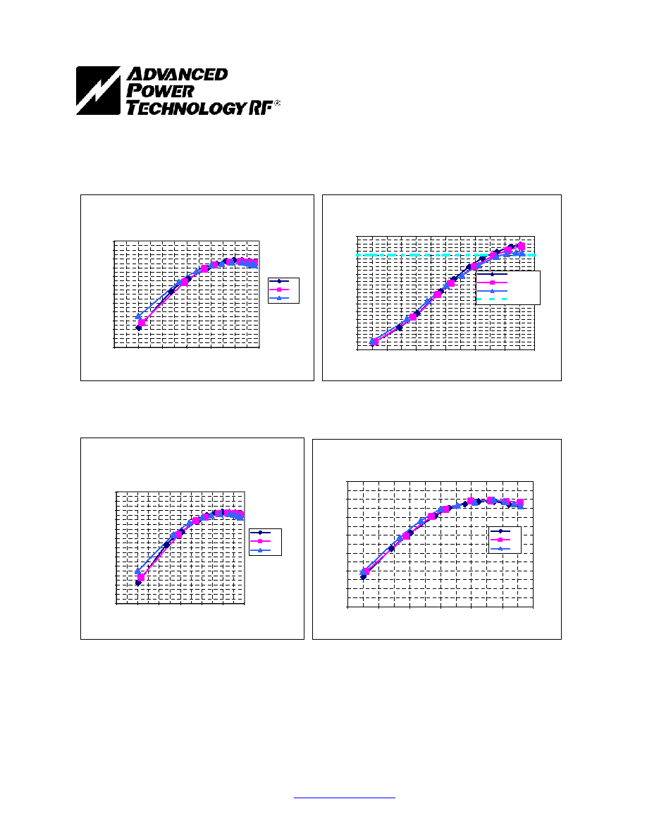
2729-125
Vcc = 36 Volts, Pulse Width = 100
µs, Duty = 10%
G2747-2, Unit 7, TF040803P2
Gain vs. Power Input -dBm
36 Volts, 100
µs, 10%
0.0
1.0
2.0
3.0
4.0
5.0
6.0
7.0
8.0
9.0
10.0
11.0
12.0
36.0
37.0
38.0
39.0
40.0
41.0
42.0
Power Input (dBm)
Power Gain (
d
B)
2.7
2.8
2.9
Power Output vs. Power In (Watts)
36Volts, 100
µs, 10%
0.0
10.0
20.0
30.0
40.0
50.0
60.0
70.0
80.0
90.0
100.0
110.0
120.0
130.0
140.0
150.0
4.0
6.0
8.0
10.0
12.0
14.0
16.0
Pin (W)
Pout
(
W
)
2.7
2.8
2.9
Expected Pout
Gain vs. Power Input -dBm
36 Volts, 100
µs, 10%
0.0
1.0
2.0
3.0
4.0
5.0
6.0
7.0
8.0
9.0
10.0
11.0
12.0
36.0
37.0
38.0
39.0
40.0
41.0
42.0
Power Input (dBm)
P
o
wer
Gain (dB)
2.7
2.8
2.9
Efficiency (%) vs Power Input (W)
36 Volts, 100
µs, 10%
0.0
10.0
20.0
30.0
40.0
50.0
60.0
70.0
4.0
6.0
8.0
10.0
12.0
14.0
16.0
Pin (W)
EFF(%)
2.7
2.8
2.9
Advanced Power Technology reserves the right to change, without notice, the specifications and information
contained herein. Visit our web site at
www.advancedpower.com
or contact our factory direct.
2729-125
Advanced Power Technology reserves the right to change, without notice, the specifications and information
contained herein. Visit our web site at
www.advancedpower.com
or contact our factory direct.

Advanced Power Technology reserves the right to change, without notice, the specifications and information
contained herein. Visit our web site at
www.advancedpower.com
or contact our factory direct.
2729-125