ADVANCED TECHNICAL
INFORMATION
MAXIMUM RATINGS
All Ratings: T
C
= 25∞C unless otherwise specified.
UNIT
Volts
Amps
Volts
Watts
W/∞C
∞C
Amps
mJ
UNIT
Volts
Amps
Ohms
µA
nA
Volts
MIN
TYP
MAX
600
49
0.110
250
1000
±100
2
4
APT6011B2VFR
600
49
196
±30
±40
625
5.0
-55 to 150
300
49
50
3000
Characteristic / Test Conditions
Drain-Source Breakdown Voltage (V
GS
= 0V, I
D
= 250µA)
On State Drain Current
2
(V
DS
> I
D(on)
x R
DS(on)
Max, V
GS
= 10V)
Drain-Source On-State Resistance
2
(V
GS
= 10V, 0.5 I
D[Cont.]
)
Zero Gate Voltage Drain Current (V
DS
= V
DSS
, V
GS
= 0V)
Zero Gate Voltage Drain Current (V
DS
= 0.8 V
DSS
, V
GS
= 0V, T
C
= 125∞C)
Gate-Source Leakage Current (V
GS
= ±30V, V
DS
= 0V)
Gate Threshold Voltage (V
DS
= V
GS
, I
D
= 2.5mA)
Symbol
V
DSS
I
D
I
DM
V
GS
V
GSM
P
D
T
J
,T
STG
T
L
I
AR
E
AR
E
AS
Parameter
Drain-Source Voltage
Continuous Drain Current @ T
C
= 25∞C
Pulsed Drain Current
1
Gate-Source Voltage Continuous
Gate-Source Voltage Transient
Total Power Dissipation @ T
C
= 25∞C
Linear Derating Factor
Operating and Storage Junction Temperature Range
Lead Temperature: 0.063" from Case for 10 Sec.
Avalanche Current
1
(Repetitive and Non-Repetitive)
Repetitive Avalanche Energy
1
Single Pulse Avalanche Energy
4
STATIC ELECTRICAL CHARACTERISTICS
Symbol
BV
DSS
I
D(on)
R
DS(on)
I
DSS
I
GSS
V
GS(th)
CAUTION: These Devices are Sensitive to Electrostatic Discharge. Proper Handling Procedures Should Be Followed.
APT Website - http://www.advancedpower.com
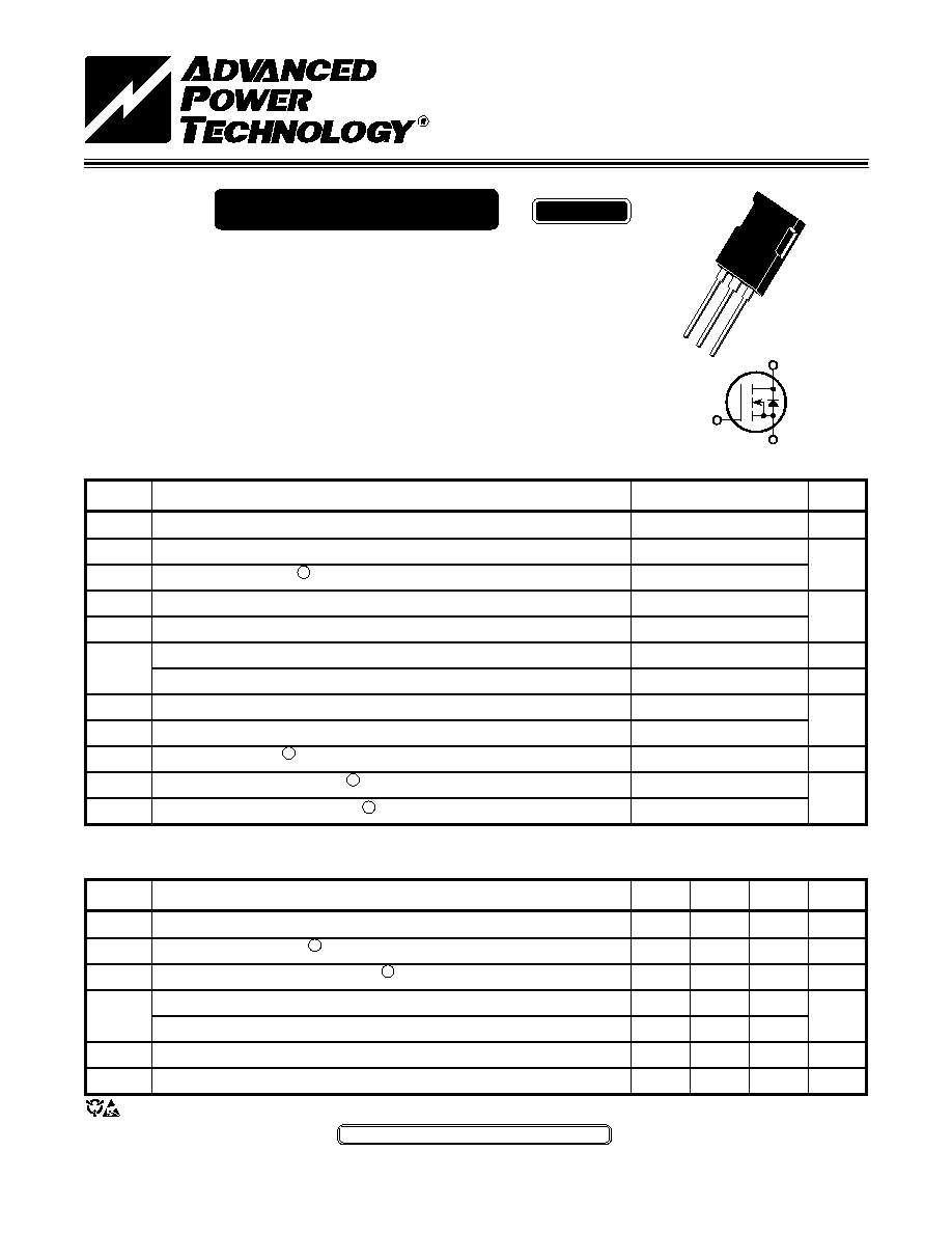
Power MOS V
Æ
is a new generation of high voltage N-Channel enhancement
mode power MOSFETs. This new technology minimizes the JFET effect,
increases packing density and reduces the on-resistance. Power MOS V
Æ
also achieves faster switching speeds through optimized gate layout.
∑ Fast Recovery Body Diode
∑ 100% Avalanche Tested
∑ Lower Leakage
∑ Faster Switching
∑ Popular
T-MAXTM
Package
POWER MOS V
Æ
FREDFET
T-MAXTM
USA
405 S.W. Columbia Street
Bend, Oregon 97702 -1035
Phone: (541) 382-8028
FAX: (541) 388-0364
EUROPE
Chemin de Magret
F-33700 Merignac - France
Phone: (33) 5 57 92 15 15
FAX: (33) 5 56 47 97 61
G
D
S
APT6011B2VFR
600V
49A
0.110
W
050-8061 rev- 01-2000
ADVANCED TECHNICAL
INFORMATION
DYNAMIC CHARACTERISTICS
APT6011B2VFR
SOURCE-DRAIN DIODE RATINGS AND CHARACTERISTICS
Characteristic / Test Conditions
Continuous Source Current (Body Diode)
Pulsed Source Current
1
(Body Diode)
Diode Forward Voltage
2
(V
GS
= 0V, I
S
= -I
D
[Cont.])
Peak Diode Recovery
dv
/
dt
5
Reverse Recovery Time
(I
S
= -I
D
[Cont.],
di
/
dt
= 100A/µs)
Reverse Recovery Charge
(I
S
= -I
D
[Cont.],
di
/
dt
= 100A/µs)
Peak Recovery Current
(I
S
= -I
D
[Cont.],
di
/
dt
= 100A/µs)
Symbol
I
S
I
SM
V
SD
dv
/
dt
t
rr
Q
rr
I
RRM
UNIT
Amps
Volts
V/ns
ns
µC
Amps
Symbol
C
iss
C
oss
C
rss
Q
g
Q
gs
Q
gd
t
d
(on)
t
r
t
d
(off)
t
f
Characteristic
Input Capacitance
Output Capacitance
Reverse Transfer Capacitance
Total Gate Charge
3
Gate-Source Charge
Gate-Drain ("Miller ") Charge
Turn-on Delay Time
Rise Time
Turn-off Delay Time
Fall Time
Test Conditions
V
GS
= 0V
V
DS
= 25V
f = 1 MHz
V
GS
= 10V
V
DD
= 0.5 V
DSS
I
D
= I
D
[Cont.] @ 25∞C
V
GS
= 15V
V
DD
= 0.5 V
DSS
I
D
= I
D
[Cont.] @ 25∞C
R
G
= 0.6
W
MIN
TYP
MAX
8310
990
390
370
51
156
17
16
63
6
UNIT
pF
nC
ns
MIN
TYP
MAX
49
196
1.3
5
T
j
= 25∞C
300
T
j
= 125∞C
600
T
j
= 25∞C
2.0
T
j
= 125∞C
6.8
T
j
= 25∞C
15
T
j
= 125∞C
27
THERMAL CHARACTERISTICS
Symbol
R
q
JC
R
q
JA
MIN
TYP
MAX
0.20
40
UNIT
∞C/W
Characteristic
Junction to Case
Junction to Ambient
APT's devices are covered by one or more of the following U.S.patents: 4,895,810
5,045,903
5,089,434
5,182,234
5,019,522
5,262,336
5,256,583
4,748,103
5,283,202
5,231,474
5,434,095
5,528,058
050-8061 rev- 01-2000
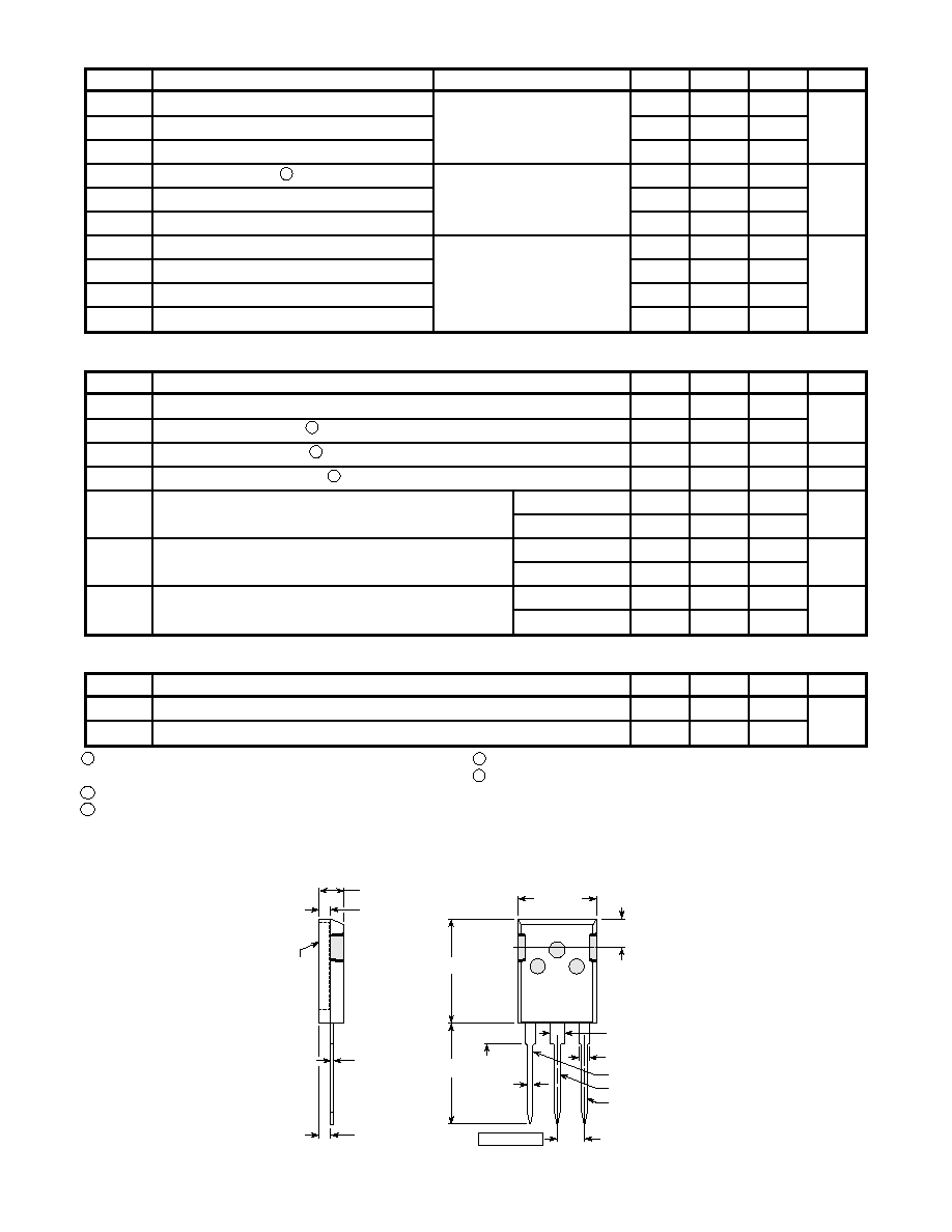
15.49 (.610)
16.26 (.640)
5.38 (.212)
6.20 (.244)
4.50 (.177) Max.
19.81 (.780)
20.32 (.800)
20.80 (.819)
21.46 (.845)
1.65 (.065)
2.13 (.084)
1.01 (.040)
1.40 (.055)
5.45 (.215) BSC
2.87 (.113)
3.12 (.123)
4.69 (.185)
5.31 (.209)
1.49 (.059)
2.49 (.098)
2.21 (.087)
2.59 (.102)
0.40 (.016)
0.79 (.031)
Drain
Source
Gate
Dimensions in Millimeters and (Inches)
Drain
2-Plcs.
These dimensions are equal to the TO-247AD without mounting hole
.
T-MAXTM Package Outline
1
Repetitive Rating: Pulse width limited by maximum junction
4
Starting T
j
=
+25∞C, L = 2.49mH, R
G
=
25
W
, Peak I
L
= 49A
temperature.
5
I
S
£
I
D
[Cont.],
di
/
dt
= 100A/µs, T
j
£
150∞C, R
G
= 2.0
W
, V
R
= 200V.
2
Pulse Test: Pulse width < 380 µS, Duty Cycle < 2%
3
See MIL-STD-750 Method 3471
APT Reserves the right to change, without notice, the specifications and information contained herein.