Document Outline
- List of Figures
- 1. Relative Intensity vs. Wavelength
- 2. Forward Current vs. Forward Voltage
- 3. Relative Luminous Intensity vs. Forward Current
- 4. Maximum Forward Current vs. Ambient Temperature
- 5. Relative Luminous Intensity vs. Angular Displacement for HSMx-S660
- 6. Relative Luminous Intensity vs. Angular Displacement for HSMx-S670
- 7. Relative Luminous Intensity vs. Angular Displacement for HSMx-S690
- 8. Recommended Solder Patterns
- 9. Recommended IR Reflow Soldering Profile
- 10. Reeling Orientation
- 11. Reel Dimensions
- 12. Tape Dimensions HSMx-S670, HSMx-S690
- 13. Tape Dimensions HSMx-S660
- 14. Tape Leader and Trailer Dimensions
- Features
- Applications
- Description
- Device Selection Guide
- Package Dimensions
- Absolute Maximum Ratings at T A = 25∫C
- Optical Characteristics at T A = 25∫C
- Electrical Characteristics at T A = 25∫C
- Yellow Color Bins [1]
- Orange Color Bins [1]
- Red Color Bins
- Luminous Intensity Bin Limits [1]
High Performance Surface Mount
Chip LEDs
Technical Data
HSMx-S660 Series
HSMx-S670 Series
HSMx-S690 Series
Features
∑ High Brightness AlInGaP
Material
∑ Industry Standard 2.00 x
1.25 mm Package
∑ Industry Standard 1.6 x 0.8
mm (Low Profile) Package
∑ Right Angle Package
∑ Three Colors Available
∑ Diffused Optics
∑ Compatible with IR Solder
Process
∑ Available in 8 mm Tape on
7" (178 mm) Diameter Reels
Applications
∑ Keypad Backlighting
∑ LCD Backlighting
∑ Symbol Backlighting
∑ Front Panel Indicator
Description
These chip-type LEDs utilize
aluminum indium gallium
phosphide (AlInGaP) material
technology. The AlInGaP material
has a very high luminous
efficiency, capable of producing
high light output over a wide
range of drive currents. The 590
nm amber, 605 nm orange, and
626 nm red colors are available
in three compact, low profile
packages.
The HSMx-S670 is the industry
standard 2.0 x 1.25 mm package,
and is an excellent all around
package. The HSMx-S690 is the
industry standard 1.6 x 0.8 mm
package. Its low 0.7 mm profile
and wide viewing angle make this
LED excellent for backlighting
SunPower Series
applications. The HSMx-S660
right angle, 3.0 x 2.0 x 1.0 mm
LED is optimum for side lighting
applications where direct back-
lighting is not practical.
All packages are compatible with
IR and convective reflow solder-
ing processes.
Device Selection Guide
Footprint
Amber
Orange
Red
(mm)
[1][2]
590 nm
605 nm
626 nm
1.6 x 0.8 x 0.7
HSMA-S690
HSMD-S690
HSMC-S690
2.0 x 1.25 x 0.8
HSMA-S670
HSMD-S670
HSMC-S670
3.0 x 2.0 x 1.0
HSMA-S660
HSMD-S660
HSMC-S660
Notes:
1. Dimensions in mm.
2. Tolerance
±
0.1 mm unless otherwise noted.
2
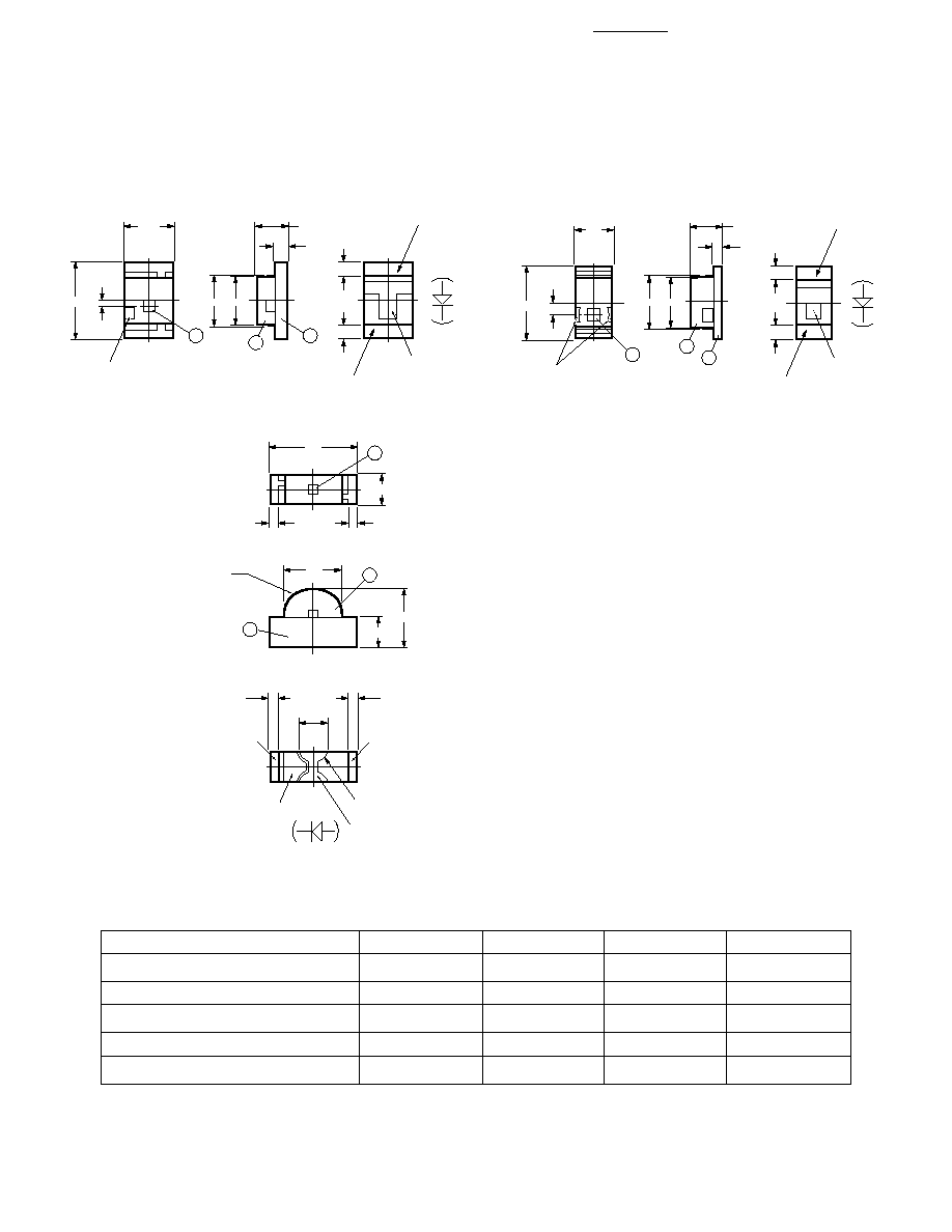
Package Dimensions
HSMx-S660 Series
HSMx-S670 Series
Notes:
1. Dimensions are in millimeters (inches).
2. Tolerance, unless otherwise specified,
±
0.1 mm (
±
0.004 inch).
HSMx-S690 Series
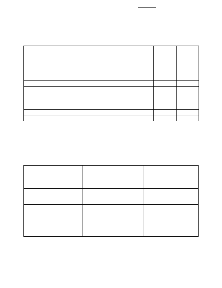
Absolute Maximum Ratings at T
A
= 25∫C
Parameter
HSMx-S660
HSMx-S670
HSMx-S690
Units
DC Forward Current
[1][2][3][4]
30
30
30
mA
Power Dissipation
81
81
81
mW
Reverse Voltage (I
R
= 100
µ
A)
5
5
5
V
Operating Temperature Range
- 40 to +85
-40 to +85
-40 to +85
∫C
Storage Temperature Range
- 40 to +100
-40 to +100
-40 to +100
∫C
Notes:
1. Derate linearly as shown in Figure 4.
2. Drive currents between 1 mA and 30 mA are recommended for best long term performance.
3. Operating at currents below 1 mA is not recommended. Please contact your Hewlett-Packard representative for further information.
4. Maximum temperature for tape and reel packaging is 60
∞
C.
2.0
1.25
CATHODE
MARK
(0.13)
1
1.3 1.2
0.8
0.3
3
2
0.35
0.35
CATHODE
POLARITY
MARK
ANODE
+ 0.1
- 0.05
1.6
0.8
CATHODE
MARK
(0.28)
1
1.2 1.1
0.7
0.2
2
0.3
CATHODE
POLARITY
MARK
ANODE
3
0.3
R0.8
1
3
PIN CONNECTION MARK
TO REINFORCE SOLDERING
(NON-PIN CONNECTION)
ANODE
3.0
1.0
0.3
0.3
1.0
2.0
2
(0.88)
0.25
0.25
R0.45
CATHODE
2.0
FRONT VIEW
TOP VIEW
REAR VIEW
3
Optical Characteristics at T
A
= 25∫C
Luminous
Color,
Intensity I
V
Peak
Dominant
Viewing
Luminous
(mcd) @ I
F
=
Wavelength
Wavelength
Angle 2
1/2
Efficacy
20 mA
[1]
peak
(nm)
d
[2]
(nm)
Degrees
[3]
V
Part Number
Color
Min.
Typ.
Typ.
Typ.
Typ.
(lm/W)
HSMA-S660
Amber
16.0
65.0
592
590
155
480
HSMA-S670
Amber
16.0
65.0
592
590
165
480
HSMA-S690
Amber
16.0
65.0
592
590
165
480
HSMD-S660
Orange
16.0
65.0
609
605
155
370
HSMD-S670
Orange
16.0
65.0
609
605
165
370
HSMD-S690
Orange
16.0
65.0
609
605
165
370
HSMC-S660
Red
16.0
50.0
630
626
155
197
HSMC-S670
Red
16.0
50.0
630
626
165
197
HSMC-S690
Red
16.0
50.0
630
626
165
197
Notes:
1. The luminous intensity I
V
is measured at the peak of the spatial radiation pattern which may not be aligned with the mechanical
axis of the lamp package.
2. The dominate wavelength
d is derived from the CIE Chromaticity Diagram and represents the perceived color of the device.
3.
1/2
is the off-axis angle where the luminous intensity is 1/2 the peak intensity.
Electrical Characteristics at T
A
= 25∫C
Forward
Reverse
Voltage V
F
Breakdown
Thermal
(Volts) @ I
F
V
R
(Volts) @
Capacitance C
Resistance
= 20 mA
I
R
= 100
µ
A
(pF), V
F
= 0,
R
J-PIN
Part Number
Color
Typ.
Max.
Min.
f = 1 MHz Typ.
(∫C/W)
HSMA-S660
Amber
1.9
2.4
5
45
600
HSMA-S670
Amber
1.9
2.4
5
45
300
HSMA-S690
Amber
1.9
2.4
5
45
300
HSMD-S660
Orange
1.9
2.4
5
45
600
HSMD-S670
Orange
1.9
2.4
5
45
300
HSMD-S690
Orange
1.9
2.4
5
45
300
HSMC-S660
Red
1.9
2.4
5
45
600
HSMC-S670
Red
1.9
2.4
5
45
300
HSMC-S690
Red
1.9
2.4
5
45
300
4
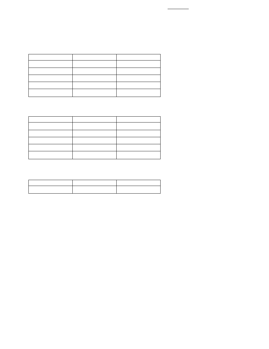
Yellow Color Bins
[1]
Bin ID
Minimum (nm)
Maximum (nm)
B
584.0
587.5
C
586.5
590.0
D
589.0
592.5
H
591.5
595.0
J
594.0
597.5
Orange Color Bins
[1]
Bin ID
Minimum (nm)
Maximum (nm)
A
596.1
600.9
B
599.1
603.9
C
602.1
606.7
D
605.3
609.7
E
608.1
612.9
Red Color Bins
Bin ID
Minimum (nm)
Maximum (nm)
A
621.0
632.0
Notes:
1. Bin categories are established for classification of products. Products may not be
available in all bin categories. Please contact your Hewlett-Packard representative for
information on currently available bins.
All products are shipped with one I
V
bin and one color bin per reel.
5
Luminous Intensity Bin Limits
[1]
Bin ID
Minimum (mcd)
Maximum (mcd)
A
0.10
0.20
B
0.16
0.32
C
0.25
0.50
D
0.40
0.80
E
0.63
1.25
F
1.00
2.00
G
1.60
3.20
H
2.50
5.00
J
4.00
8.00
K
6.30
12.50
L
10.00
20.00
M
16.00
32.00
N
25.00
50.00
P
40.00
80.00
Q
63.00
125.00
R
100.00
200.00
S
160.00
320.00
T
250.00
500.00
U
400.00
800.00
V
630.00
1250.00
W
1000.00
2000.00
X
1600.00
3200.00
Y
2500.00
5000.00
Note:
1. Bin categories are established for classification of products. Products may not be
available in all bin categories. Please contact your Hewlett-Packard representative for
information on currently available bins.