 | ÐлекÑÑоннÑй компоненÑ: HSMH-L640 | СкаÑаÑÑ:  PDF PDF  ZIP ZIP |
Äîêóìåíòàöèÿ è îïèñàíèÿ www.docs.chipfind.ru
HSMA-L640
HSMC-L640
HSMH-L640
HSMG-L640
AS AlInGaP
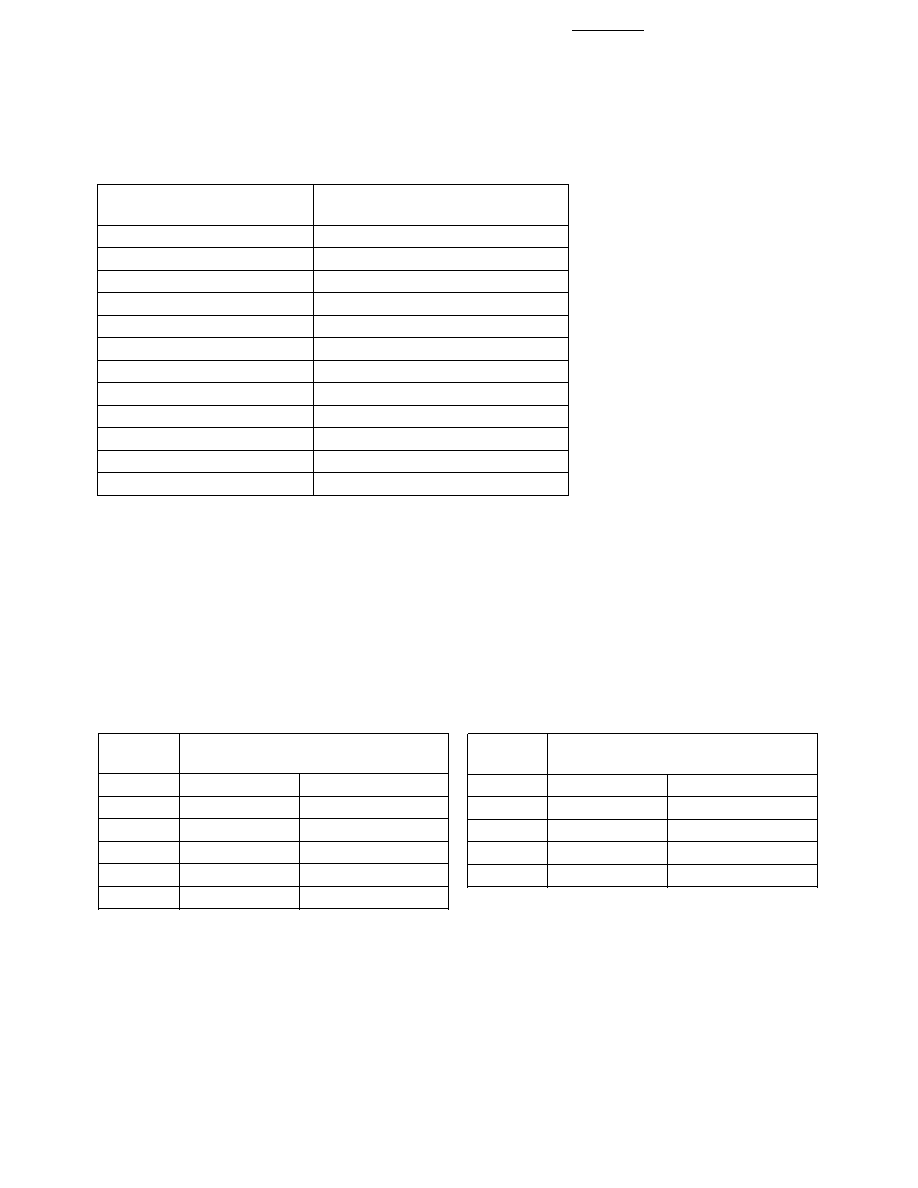
Product Part Number
Color
Package Description
HSMA-L640
Amber 590 nm
Untinted, Non-diffused
HSMC-L640
Red 626 nm
Untinted, Non-diffused
Features
·
High Brightness AlInGaP
Material (HSMA & HSMC)
·
Various Colors Available
·
Compatible with IR Solder
Process
·
Narrow Viewing Angle
·
Small 3.0 x 1.5 mm Package
·
Available in 8 mm Tape on 7"
(180 mm) Diameter Reels
Applications
·
Keypad Backlighting
·
Light Piping
·
LCD Backlighting
·
Front Panel Indicator
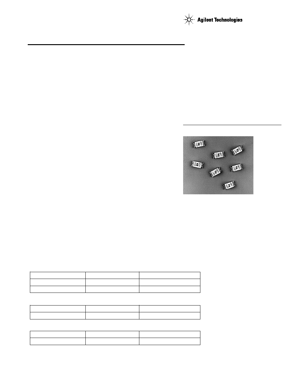
Description
The HSMx-L640 is a Chip LED
with an integrated lens. The lens
concentrates the emitted light into
a narrow viewing angle, which has
the effect of doubling the on-axis
intensity. These LEDs are
optimum for light piping,
backlighting buttons and switches,
and applications, where as much
flux as possible is required on axis.
The available colors are AlInGap
Amber, AlInGap Red, AlGaAs Red
and GaP Green.
The 3.0 x 1.5 mm package closely
matches industry standard sizes for
chip capacitors which makes it
compatible with automated pick
and place equipment.
This package is compatible with IR
and convective reflow soldering
processes.
Device Selection Guide
Surface Mount Lensed
Chip LEDs
Technical Data
GaP
Product Part Number
Color
Package Description
HSMG-L640
Green 571 nm
Untinted, Non-diffused
AlGaAs
Product Part Number
Color
Package Description
HSMH-L640
Red 639 nm
Untinted, Non-diffused
2
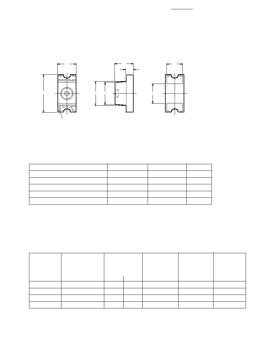
Package Dimensions
Notes:
1. Dimensions are in millimeters.
2. Tolerance,
±
0.2 mm
Absolute Maximum Ratings at T
A
= 25
°
C
Parameter
HSMA/C-L640
HSG/H-L640
Units
DC Forward Current
[3][4][5]
30
25
mA
Power Dissipation
81
65
mW
Reverse Current V
R
= 5 V
100
100
µ
A
Operating Temperature Range
-30 to +85
-30 to +85
°
C
Storage Temperature Range
[6]
-40 to +100
-40 to +100
°
C
Notes:
3. Derate linearly as shown in Figure 4.
4. Drive currents between 1 mA and the specified maximum DC forward current are recommended for best long
term performance.
5. Operating at currents below 1 mA is not recommended. Please contact your Agilent representative for further
information.
6. Maximum temperature for tape and reel packaging is 60
°
C.
Optical Characteristics at T
A
= 25
°
C
Luminous
Color,
Viewing
Intensity
Peak
Dominant
Angle
I
V
(mcd)
Wavelength
Wavelength
2
1
/
2
Part
@I
F
20 mA
[7]
peak
(nm)
d
[8]
(nm)
Degrees
[9]
Number
Color
Min.
Typ.
Typ.
Typ.
Typ.
HSMA-L640
AS AlInGaP Amber
63
130
592
590
70
HSMC-L640
AS AlInGaP Red
63
100
635
626
70
HSMG-L640
GaP Green
10
18
570
572
70
HSMH-L640
AlGaAs Red
10
32
650
639
70
Notes:
7. The luminous intensity, I
V
, is measured at the peak of the spatial radiation pattern.
8. The dominant wavelength,
d
, is derived from the CIE Chromaticity diagram, and represents the perceived color of the device.
9.
1/2
is the off-axis angle where the luminous intensity is
1
/
2
the peak intensity.
2
1.8
0.6
3
1.5
CATHODE
MARK
1.5
1.6
1.3
TOLERANCES: ± 0.2 mm
3
Electrical Characteristics at T
A
= 25
°
C
Forward
Reverse
Capacitance
Voltage
Breakdown
C (pF)
Thermal
V
F
(Volts)
V
R
(Volts)
V
F
= 0
Resistance
Part
@ I
F
= 20 mA
@ I
R
= 100
µ
A
f = 1 MHz
R
J-PIN
(
°
C/W)
Number
Color
Typ.
Max.
Min.
Typ.
Typ.
HSMA-L640
AS AlInGaP
2.02
2.40
5
40.0
500
Amber
HSMC-L640
AS AlInGaP Red
1.90
2.40
5
40.0
500
HSMG-L640
GaP Green
2.20
2.60
5
8.0
475
HSMH-L640
AlGaAs Red
1.80
2.20
5
4.5
475
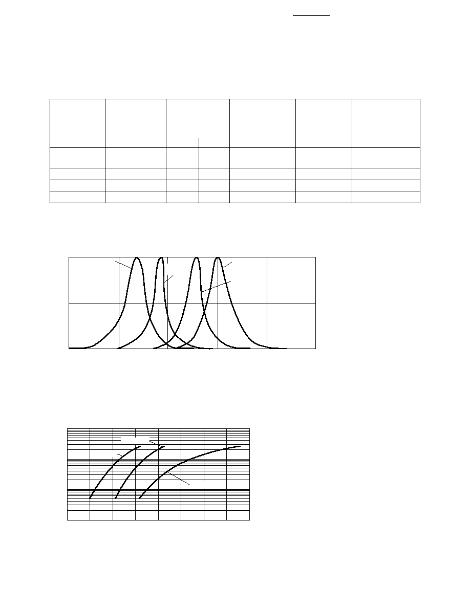
Figure 1. Relative Intensity vs. Wavelength.
Figure 2. Forward Current vs. Forward Voltage.
WAVELENGTH nm
AlGaAs RED
GREEN
RELATIVE INTENSITY
1.0
0.5
0
500
550
600
650
700
750
AlInGaP RED
AlInGaP
AMBER
100
10
1
0.1
1.5
1.6
2.0
2.3
VF FORWARD VOLTAGE V
I F
FORWARD CURRENT mA
AS AllnGaP
1.7
1.8
1.9
2.1
2.2
AlGaAs
GaP GREEN
4
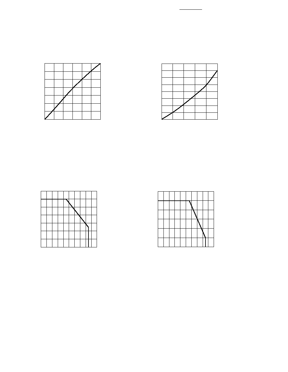
Figure 4a. Maximum DC Current vs.
Ambient Temperature for AlInGaP.
0
35
0
20
60
80
100
30
5
I F
FORWARD CURRENT mA
TA AMBIENT TEMPERATURE °C
40
15
20
25
10
Figure 3a. Relative Luminous Intensity vs.
DC Forward Current for AlInGaP.
0
5
15
30
IF FORWARD CURRENT mA
0
0.4
1.0
1.4
LUMINOUS INTENSITY
(NORMALIZED AT 20 mA)
20
0.6
0.2
0.8
10
25
1.2
0
5
10
15
20
25
IDC DC FORWARD CURRENT mA
0
0.2
0.4
0.6
0.8
1.0
1.2
1.4
1.6
RELATIVE LUMINOUS INTENSITY
(NORMALIZED AT 20 mA)
Figure 3b. Relative Luminous Intensity vs.
DC Forward Current for GaP and AlGaAs.
0
30
0
20
60
80
100
5
I F
FORWARD CURRENT mA
TA AMBIENT TEMPERATURE °C
40
15
20
25
10
Figure 4a. Maximum DC Current vs. Ambient
Temperature for AlGaAs and GaP.
5
Light Intensity (Iv) Bin Limits
[1]
Intensity (mcd)
Intensity (mcd)
Bin ID
Min.
Max.
Bin ID
Min.
Max.
A
0.11
0.18
N
28.50
45.00
B
0.18
0.29
P
45.00
71.50
C
0.29
0.45
Q
71.50
112.50
D
0.45
0.72
R
112.50
180.00
E
0.72
1.10
S
180.00
285.00
F
1.10
1.80
T
285.00
450.00
G
1.80
2.80
U
450.00
715.00
H
2.80
4.50
V
715.00
1125.00
J
4.50
7.20
W
1125.00
1800.00
K
7.20
11.20
X
1800.00
2850.00
L
11.20
18.00
Y
2850.00
4500.00
M
18.00
28.50
Note:
1. Bin categories are established for classification of products. Products may not be available
in all categories. Please contact your Agilent representative for information on currently
available bins.
Tolerance:
±
15%
Color Bin Limits
[1]
Green Color Bins
[1]
Dom. Wavelength (nm)
Bin ID
Min.
Max.
A
561.5
564.5
B
564.5
567.5
C
567.5
570.5
D
570.5
573.5
E
573.5
576.5
Amber Color Bins
[1]
Dom. Wavelength (nm)
Bin ID
Min.
Max.
A
582.0
584.5
B
584.5
587.0
C
587.0
589.5
D
589.5
592.0
E
592.0
594.5
F
594.5
597.0
Tolerance:
±
0.5 nm
Tolerance:
±
0.5 nm
Note:
1. Bin categories are established for classification or products. Products may not be available in all bin categories. Pleae contact your
Agilent representative for information of currently available bins.