
Description
This series of right angle mount
ChipLEDs is designed with the
smallest footprint to achieve high
density of components on board.
They have the industry standard
footprint of 1.6 mm x 1.0 mm
and a height of only 0.6 mm. This
makes them very suitable for
cellular phone and mobile
equipment backlighting and
Agilent HSMA/C/L-C120,
HSMD/G/S/H-C120, HSMM/N/Q/R-C120
Right Angle ChipLED
Data Sheet
Features
∑ Small size right angle mount
∑ 0603 industry standard footprint
∑ Operating temperature range of
≠30∞C to +85∞C
∑ Available in various colors
∑ Compatible with IR solder reflow
∑ Available in 8 mm tape on 7"
diameter reel
∑ Reel sealed in zip locked
moisture barrier bags
Applications
∑ LCD backlighting
∑ Keypad backlighting
∑ Pushbutton backlighting
∑ Symbol indicator
CAUTION: HSMM/N/Q/R-C120 LEDs are Class 1 ESD sensitive per MIL-STD-1686. Please observe
appropriate precautions during handling and processing. Refer to Agilent Technologies Application
Note AN-1142 for additional details.
indication application where
space is a constraint. They are
available in a wide range of color
combination. In order to facilitate
automated pick and place
operation, these ChipLEDs are
shipped in tape and reel, with
4000 units per reel. These parts
are compatible with IR soldering.

2
Package Dimensions
Device Selection Guide
AS AlInGaP
InGaN
Amber
Red
Orange
Green
Blue
Package Description
HSMA-C120
HSMC-C120
HSML-C120
HSMM-C120
HSMN-C120
Untinted,
HSMQ-C120
HSMR-C120
Non Diffused
AlGaAs
GaP
Red
Green
Orange
HER
Package Description
HSMH-C120
HSMG-C120
HSMD-C120
HSMS-C120
Untinted, Non Diffused
1.6 (0.063)
0.4 (0.016)
POLARITY
[3]
CATHODE MARK
(ANODE MARK FOR HSMH-C120)
1.0 (0.039)
3 ≠ 0.3 (0.012)
1.2 (0.047)
0.3 (0.012)
LED DIE
CLEAR
EPOXY
PC BOARD
SOLDERING
TERMINAL
0.6 (0.024)
CATHODE LINE
NOTES:
1. ALL DIMENSIONS IN MILLIMETERS (INCHES).
2. TOLERANCE IS ± 0.1 mm (± 0.004 IN.) UNLESS OTHERWISE SPECIFIED.
3. POLARITY FOR HSMH-C120 WILL BE THE OPPOSITE OF WHAT IS SHOWN ON ABOVE DRAWING.
3
Absolute Maximum Ratings at T
A
= 25∞C
HSMA/C/L-
HSMD/G/S-
HSMH-
HSMM/N-
HSMQ/R-
Parameter
C120
C120
C120
C120
C120
Units
DC Forward Current
[1] [2]
25
20
25
20
20
mA
Power Dissipation
60
52
65
78
78
mW
Reverse Voltage (I
R
= 100
µ
A)
5
5
5
5
5
V
LED Junction Temperature
95
95
95
95
95
∞C
Operating Temperature Range
≠30 to +85
∞C
Storage Temperature Range
≠40 to +85
∞C
Soldering Temperature
See IR soldering profile (Figure 6)
Notes:
1. Derate linearly as shown in Figure 4.
2. Drive currents above 5 mA are recommended for best long term performance.
Electrical Characteristics at T
A
= 25∞C
Forward
Reverse
Voltage
Breakdown
Capacitance C
Thermal
V
F
(Volts)
V
R
(Volts)
(pF), V
F
= 0,
Resistance
@ I
F
= 20 mA
@ I
R
= 100
µ
A
f = 1 MHz
R
J-PIN
(∞C/W)
Part Number
Typ.
Max.
Min.
Typ.
Typ.
HSMA-C120
1.9
2.4
5
11
400
HSMC-C120
1.9
2.4
5
15
400
HSML-C120
1.9
2.4
5
20
400
HSMD-C120
2.2
2.6
5
7
350
HSMG-C120
2.2
2.6
5
9
350
HSMS-C120
2.1
2.6
5
5
350
HSMH-C120
1.8
2.6
5
20
400
HSMM-C120
3.4
3.9
5
45
450
HSMN-C120
3.4
3.9
5
45
450
HSMQ-C120
3.4
3.9
5
100
450
HSMR-C120
3.4
3.9
5
100
450
Note:
1. V
F
tolerance:
±
0.1 V

4
Color Bin Limits
[1]
Green Color Bins
Dom. Wavelength (nm)
Bin ID
Min.
Max.
A
561.5
564.5
B
564.5
567.5
C
567.5
570.5
D
570.5
573.5
E
573.5
576.5
Tolerance:
±
0.5 nm
Light Intensity (I
v
) Bin Limits
[1]
Intensity (mcd)
Bin ID
Min.
Max.
A
0.11
0.18
B
0.18
0.29
C
0.29
0.45
D
0.45
0.72
E
0.72
1.10
F
1.10
1.80
G
1.80
2.80
H
2.80
4.50
J
4.50
7.20
K
7.20
11.20
L
11.20
18.00
M
18.00
28.50
N
28.50
45.00
P
45.00
71.50
Q
71.50
112.50
R
112.50
180.00
S
180.00
285.00
T
285.00
450.00
U
450.00
715.00
Tolerance:
±
15%
Optical Characteristics at T
A
= 25∞C
Luminous
Intensity
Peak
Dominant
Luminous
I
v
(mcd)
Wavelength
Wavelength
Viewing Angle
Efficacy
@ 20 mA
[1]
peak
[2]
(nm)
d
[2]
(nm)
2
1/2
Degrees
[3]
v
(lm/w)
Part Number
Min.
Typ.
Typ.
Typ.
Typ.
Typ.
HSMA-C120
25
90
595
592
155
480
HSMC-C120
25
90
637
626
155
155
HSML-C120
25
90
609
605
155
370
HSMD-C120
2.5
8
605
604
155
380
HSMG-C120
4.0
15
570
572
155
595
HSMS-C120
2.5
10
630
626
155
145
HSMH-C120
4.0
15
660
639
155
70
HSMM-C120
40
120
523
525
155
490
HSMN-C120
10
30
468
470
155
80
HSMQ-C120
40
145
520
527
155
500
HSMR-C120
16
55
469
473
155
85
Notes:
1.The luminous intensity I
v
is measured at the peak of the spatial radiation pattern which may not be aligned with the mechanical
axis of the lamp package.
2.The coordinate is derived from the CIE Chromatically Diagram and represents the perceived color of the device.
3.
1/2
is the off-axis angle where the luminous intensity is 1/2 the peak intensity.
Yellow/Amber Color Bins
Dom. Wavelength (nm)
Bin ID
Min.
Max.
A
582.0
584.5
B
584.5
587.0
C
587.0
589.5
D
589.5
592.0
E
592.0
594.5
F
594.5
597.0
Tolerance:
±
0.5 nm
Blue Color Bins
Dom. Wavelength (nm)
Bin ID
Min.
Max.
A
460.0
465.0
B
465.0
470.0
C
470.0
475.0
D
475.0
480.0
Tolerance:
±
1 nm
InGaN Green Color Bins
Dom. Wavelength (nm)
Bin ID
Min.
Max.
A
515.0
520.0
B
520.0
525.0
C
525.0
530.0
D
530.0
535.0
Tolerance:
±
1 nm
5
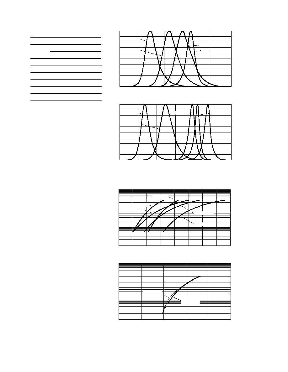
Figure 1. Relative intensity vs. wavelength.
Figure 2. Forward current vs. forward voltage.
Color Bin Limits
Orange Color Bins
Dom. Wavelength (nm)
Bin ID
Min.
Max.
A
597.0
600.0
B
600.0
603.0
C
603.0
606.0
D
606.0
609.0
E
609.0
612.0
F
612.0
615.0
Tolerance:
±
1 nm
Notes:
1.Bin categories are established for
classification of products. Products may not
be available in all categories.
Please contact your Agilent representative
for information on currently available bins.
100
50
0
500
550
600
650
700
750
RELATIVE INTENSITY ≠ %
WAVELENGTH - nm
GaP GREEN
90
80
70
60
40
30
20
10
GaP ORANGE
HER
AlGaAs RED
100
50
0
400
450
550
600
650
700
RELATIVE INTENSITY ≠ %
WAVELENGTH - nm
InGaN BLUE
90
80
70
60
40
30
20
10
AS ORANGE
500
InGaN GREEN
AS AMBER
AS RED
GaP ORANGE
100
10
1
0.1
1.5
1.6
2.0
2.3
VF ≠ FORWARD VOLTAGE ≠ V
I F
≠ FORWARD CURRENT ≠ mA
AS AllnGaP
1.7
1.8
1.9
2.1
2.2
AlGaAs
HER
GaP GREEN
100
10
1
0.1
1.5
2.0
4.0
VF ≠ FORWARD VOLTAGE ≠ V
I F
≠ FORWARD CURRENT ≠ mA
HSMM,
HSMN InGaN
2.5
3.0
3.5
HSMQ,
HSMR InGaN