Agilent HSMx-C540
Oval Lens High Performance
Surface Mount LEDs
Data Sheet
Description
These high performance
HSMx-C540 surface mount LEDs
are specifically designed for indoor
full color signs and passenger infor-
mation signs. The oval shaped
radiation pattern (40
°
x 100
°
) and
high luminous intensity ensure that
these devices are excellent for wide
field of view indoor applications.
These lamps have a very smooth
matched radiation pattern that
ensures consistent color mixing in
full color applications, and message
uniformity across the viewing angle
of the sign.
High efficiency LED dice are used
in these LED components. InGaN
(Indium Gallium Nitride) for green
and blue and AlInGaP (Aluminium
Indium Gallium Phosphide) for red
LED Part Numbers HSMA-C540, HSMC-C540,
HSMM-C540, HSMN-C540, HSMU-C540, HSMZ-C540
Features
· Super wide viewing angle
Major axis 100
°
Minor axis 40
°
· Smooth, consistent spatial
radiation pattern
· Small 2.0 x 1.25 mm footprint
· High luminous output
· Compatible with IR solder reflow
· Colors available: 626/629 nm red,
590 nm amber, 525 nm green,
470 nm blue
· Available in 8 mm tape on 7"
(178 mm) diameter reels
· Tinted, non-diffused epoxy
Applications
· Indoor full color sign
· Commercial indoor advertising
· Indoor variable message sign
· Status indication
· Front panel indicator
Benefits
· Viewing angle designed for wide
field of view application
· Red, green, blue radiation patterns
matched for indoor full color signs
· Small package footprint enables
small pitch size for full color signs
· Superior for indoor full color signs
CAUTION: HSMM-C540 and HSMN-C540 LEDs are Class 1 ESD sensitive. Please observe appropriate precautions
during handling and processing. Refer to Agilent Technologies Application Note AN-1142 for additional details.
and amber are capable of produc-
ing high light output.
The HSMx-C540 has an industry
standard 2.0 x 1.25 mm footprint
that is excellent for all-around use.
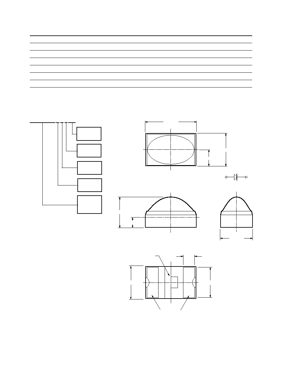
These solid state surface mount
LEDs are designed with a reflector
cup and oval shape dome which
provides directional lighting. The
reflector cup focuses the light
more efficiently to provide higher
intensity compared to a
nonreflector cup equivalent part.
The oval dome produces oval
radiation pattern for wide field of
view indoor applications.
All packages are compatible with
IR soldering process and are
shipped in tape and reel with
3000 units per reel.

3
Absolute Maximum Ratings at T
A
= 25°C
Parameter
AlInGaP
InGaN
Units
DC Forward Current
[1]
30
25
mA
Peak Pulsing Current
[2]
100
100
mA
Power Dissipation
78
105
mW
Reverse Voltage (I
R
= 10
µ
A)
5
V
Reverse Voltage (I
R
= 100
µ
A)
5
V
LED Junction Temperature
95
95
°C
Operating Temperature Range
40 to +85
40 to +85
°C
Storage Temperature Range
40 to +100
40 to +100
°C
Soldering Temperature
See IR soldering profile (Figure 8)
Notes:
1. Derate linearly as shown in Figure 4.
2. Pulse condition of 1/10 duty and 0.1 ms width.
Electrical Characteristics at T
A
= 25°C
Forward Voltage
Reverse Breakdown
Reverse Breakdown
Capacitance C
Thermal
V
F
(Volts)
V
R
(Volts)
V
R
(Volts)
(pF), V
F
= 0,
Resistance
@ I
F
= 20 mA
@ I
R
= 100
µ
A
@ I
R
= 10
µ
A
f = 1 MHz
R
JPIN
(°C/W)
Part Number
Typ.
Max.
Min.
Min.
Typ.
Typ.
HSMA-C540
2.0
2.6
5
17
485
HSMC-C540
2.0
2.6
5
17
485
HSMM-C540
3.8
4.2
5
50
380
HSMN-C540
3.8
4.2
5
50
380
HSMU-C540
2.2
2.6
5
30
485
HSMZ-C540
2.2
2.6
5
30
485
Optical Characteristics at T
A
= 25°C
Luminous
Color,
Viewing
Luminous
Intensity
Peak
Dominant
Angle
Efficacy
I
V
(mcd)
Wavelength
Wavelength
2
1/2
V
@ 20 mA
[1]
peak
(nm)
d
[2]
(nm)
Degrees
[3]
(lm/w)
Part Number
Color
Min.
Typ.
Typ.
Typ.
Typ.
Typ.
HSMA-C540
As AlInGaP Amber 96
160
592
590
100
°
/40
°
470
HSMC-C540
As AlInGaP Red
96
210
635
626
100
°
/40
°
175
HSMM-C540
InGaN Green
57
230
523
525
100
°
/40
°
475
HSMN-C540
InGaN Blue
26
55
468
470
100
°
/40
°
70
HSMU-C540
TS AlInGaP Amber 157
270
592
590
100
°
/40
°
550
HSMZ-C540
TS AlInGaP Red
209
350
641
629
100
°
/40
°
145
Notes:
1. The luminous intensity, I
V
, is measured at the peak of the spatial radiation pattern, which may not be aligned with the mechanical axis of the
lamp package.
2. The dominant wavelength,
d
, is derived from the CIE Chromatically Diagram and represents the perceived color of the device.
3.
1/2
is the off-axis angle where the luminous intensity is 1/2 the peak intensity.
4
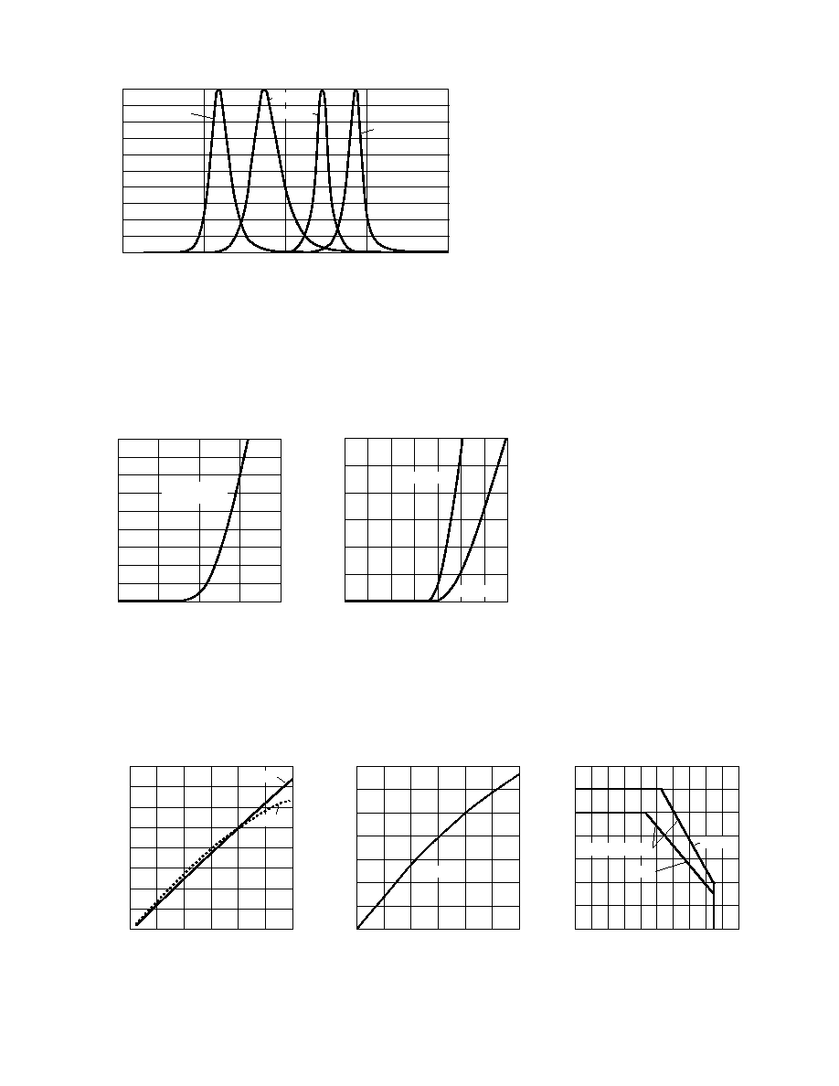
Figure 1. Relative intensity vs. wavelength.
Figure 2. Forward current vs. forward voltage.
1
2
3
5
FORWARD VOLTAGE V
0
5
30
45
FORWARD CURRENT mA
4
20
40
25
10
35
15
InGaN GREEN
and BLUE
Figure 4. Maximum forward current vs.
ambient temperature.
Figure 3. Luminous intensity vs. forward current.
0
5
15
30
IF FORWARD CURRENT mA
0
0.2
1.4
LUMINOUS INTENSITY
(NORMALIZED AT 20 mA)
25
0.8
1.2
0.4
1.0
0.6
10
20
InGaN
WAVELENGTH nm
BLUE
RELATIVE INTENSITY
1.0
0.5
0
350
450
550
650
750
RED
0.4
0.3
0.2
0.1
0.6
0.7
0.8
0.9
GREEN
AMBER
1.0
1.4
1.8
2.4
FORWARD VOLTAGE V
0
5
30
FORWARD CURRENT
2.2
20
25
10
15
1.2
1.6
2.0
AS AlInGaP
TS AlInGaP
0
5
15
30
IF FORWARD CURRENT mA
0
0.2
1.0
1.6
LUMINOUS INTENSITY
(NORMALIZED AT 20 mA)
25
0.8
1.4
0.4
1.2
0.6
10
20
AMBER
RED
0 10
50
100
TA AMBIENT TEMPERATURE °C
0
5
35
I F MAX.
MAXIMUM FORWARD CURRENT mA
80
20
30
10
25
15
20
60
AlInGaP
R
J-A = 600°C/W
30 40
70
90
InGaN