Features
∑ High brightness
∑ Small size
∑ Industrial standard footprint
∑ Diffused optics
∑ Top emitting or right angle
emitting
∑ Compatible with IR soldering
∑ Compatible for use with light
piping
∑ Available in 8 mm tape on
7" diameter reel
∑ Reel sealed in zip locked moisture
barrier bags
Applications
∑ LCD backlighting
∑ Push button backlighting
∑ Front panel indicator
∑ Symbol indicator
∑ Microdisplays
∑ Small message panel signage
Description
These small chip-type LEDs utilize
high efficient and high brightness
InGaN material to deliver
competitively priced high
performance blue and green. These
520 nm green and 470 nm blue are
unique hues which provide color
differentiation to a product.
These ChipLEDs come in either top
emitting packages (HSMx-C130,
C150, C170, C177, C190, C191,
C197), in side emitting packages
(HSMx-C110, C120) or in a reverse
mount package (C265). The side
emitting package is especially
suitable for LCD backlighting
application. The top emitting
packages, with their wide viewing
angle, are suitable for direct
backlighting application or being
used with light pipes. In order to
facilitate pick and place operation,
these ChipLEDs are shipped in
tape and reel with 4000 units per
reel for HSMx-C120, C130, C170,
C177, C190, C191 and C197
packages, and 3000 units per reel
for HSMx-C110, C150 and C265
packages. All packages are
compatible with IR soldering and
binned by both color and intensity.
Agilent HSMx-C1xx
High Performance Chip LED
Data Sheet
HSMQ-C110/120/150/170/177/190/191/197/265,
HSMR-C110/120/130/150/170/177/190/191/197/265
CAUTION: HSMQ-C1xx and HSMR-C1xx are Class 1 ESD sensitive per MIL-STD-1686. Please observe
appropriate precautions during handling and processing. Refer to Agilent Technologies Application Note
AN-1142 for additional details.

4
Absolute Maximum Ratings at T
A
= 25∞C
HSMQ-Cxxx
Parameter
HSMR-Cxxx
Units
DC Forward Current
[1]
20
mA
Power Dissipation
78
mW
Reverse Voltage (I
R
= 100
µ
A)
5
V
LED Junction Temperature
95
∞C
Operating Temperature Range
≠30 to +85
∞C
Storage Temperature Range
≠40 to +85
∞C
Soldering Temperature
See reflow soldering profile (Figures 11 & 12)
Device Selection Guide
Package Dimension (mm)
[1], [2]
InGaN Green
InGaN Blue
Package Description
3.2(L) x 1.0(W) x 1.5(H)
HSMQ-C110
HSMR-C110
Untinted, Non-diffused
1.6(L) x 0.6(W) x 1.0(H)
HSMQ-C120
HSMR-C120
Untinted, Non-diffused
1.6(L) x 0.8(W) x 0.35(H)
≠
HSMR-C130
Untinted, Diffused
3.2(L) x 1.6(W) x 1.1(H)
HSMQ-C150
HSMR-C150
Untinted, Diffused
2.0(L) x 1.25(W) x 0.8(H)
HSMQ-C170
HSMR-C170
Untinted, Diffused
2.0(L) x 1.25(W) x 0.4(H)
HSMQ-C177
HSMR-C177
Untinted, Diffused
1.6(L) x 0.8(W) x 0.8(H)
HSMQ-C190
HSMR-C190
Untinted, Diffused
1.6(L) x 0.8(W) x 0.6(H)
HSMQ-C191
HSMR-C191
Untinted, Diffused
1.6(L) x 0.8(W) x 0.4(H)
HSMQ-C197
HSMR-C197
Untinted, Diffused
3.4(L) x 1.25(W) x 1.1(H)
HSMQ-C265
HSMR-C265
Untinted, Non-diffused
Notes: 1. Dimensions in mm. 2. Tolerance
±
0.1 mm unless otherwise noted.
Note: 1. Derate linearly as shown in Figure 4.
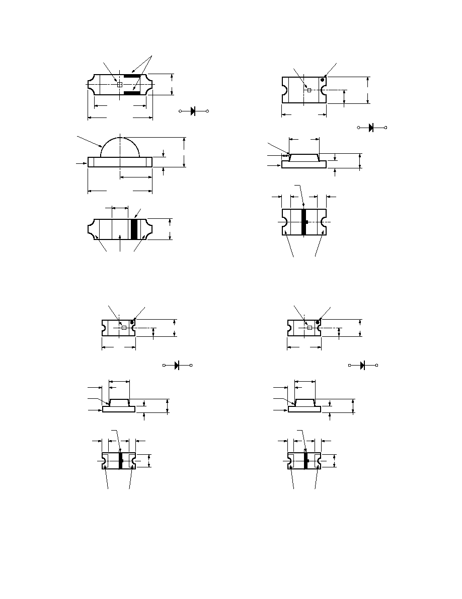
NOTES:
1. ALL DIMENSIONS IN MILLIMETERS (INCHES).
2. TOLERANCE IS ± 0.1 mm (± 0.004 IN.) UNLESS OTHERWISE SPECIFIED.
Package Dimensions, continued
1.6
(0.063)
0.12 (0.005)
0.3 ± 0.15
(0.012 ± 0.006)
0.23 (0.009)
CATHODE
MARK
0.35 (0.014)
0.3 ± 0.15
(0.012 ± 0.006)
1.15
(0.045)
LED DIE
DIFFUSED EPOXY
PCB BOARD
0.8 (0.031)
CATHODE LINE
0.7 (0.028) MIN.
POLARITY
(0.625)
SOLDERING
TERMINAL
HSMx-C130
3.4 (0.134)
0.3 (0.012)
0.50 ± 0.15
(0.020 ± 0.006)
1.1 (0.043)
POLARITY
CATHODE
MARK (ETCHED)
1.1 (0.043)
0.50 ± 0.15
(0.020 ± 0.006)
1.2
(0.047)
1.25 (0.049)
LED DIE
UNDIFFUSED
EPOXY
PC BOARD
SOLDERING
TERMINAL
GREEN SOLDER MASK
CATHODE LINE
HSMx-C265
5
Optical Characteristics at T
A
= 25∞C
Luminous
Color,
Viewing
Luminous
Intensity
Peak
Dominant
Angle
Efficacy
I
V
(mcd)
Wavelength
Wavelength
2
1/2
V
@ 20 mA
[1]
peak
(nm)
d
[2]
(nm)
Degrees
[3]
(lm/w)
Part Number
Color
Min.
Typ.
Typ.
Typ.
Typ.
Typ.
HSMQ-C110
Green
45
150
520
527
130
500
HSMQ-C120
Green
45
145
520
527
155
500
HSMQ-C150/170/190/191
Green
45
145
520
527
140
500
HSMQ-C177/197
Green
45
145
520
527
130
500
HSMQ-C265
Green
45
140
520
527
150
500
HSMR-C110
Blue
18
60
469
473
130
88
HSMR-C120
Blue
18
55
469
473
155
88
HSMR-C130
Blue
18
55
469
473
145
88
HSMR-C150/170/190/191
Blue
18
55
469
473
140
88
HSMR-C177/197
Blue
18
55
469
473
130
88
HSMR-C265
Blue
18
45
469
473
150
88
Notes:
1. The luminous intensity, I
V
, is measured at the peak of the spatial radiation pattern which may not be aligned with the mechanical axis of the lamp package.
2. The dominant wavelength,
d
, is derived from the CIE Chromaticity Diagram and represents the perceived color of the device.
3.
1/2
is the off-axis angle where the luminous intensity is 1/2 the peak intensity.
Electrical Characteristics at T
A
= 25∞C
Forward Voltage
Reverse Breakdown
Capacitance C
Thermal
V
F
(Volts)
V
R
(Volts)
(pF), V
F
= 0,
Resistance
@ I
F
= 20 mA
@ I
R
= 100
µ
A
f = 1 MHz
R
J≠PIN
(∞C/W)
Part Number
Typ.
Max.
Min.
Typ.
Typ.
HSMQ-C110/C150
3.4
3.9
5
140
450
HSMR-C110/C150
3.4
3.9
5
140
450
HSMQ-C120
3.4
3.9
5
100
450
HSMR-C120/C130
3.4
3.9
5
100
450
HSMQ-C170/C190/C191
3.4
3.9
5
110
300
HSMR-C170/C190/C191
3.4
3.9
5
110
300
HSMQ-C177/C197
3.4
3.9
5
110
350
HSMR-C177/C197
3.4
3.9
5
110
350
HSMQ-C265
3.4
3.9
5
65
300
HSMR-C265
3.4
3.9
5
65
300
V
F
Tolerance:
±
0.1 V
Blue Color Bins
[1]
Dom. Wavelength (nm)
Bin ID
Min.
Max.
A
460.0
465.0
B
465.0
470.0
C
470.0
475.0
D
475.0
480.0
Note:
1. Bin categories are established for classification of products. Products may not be available in all categories. Please contact your Agilent
representative for information on currently available bins.
Color Bin Limits
[1]
InGaN Green Color Bins
[1]
Dom. Wavelength (nm)
Bin ID
Min.
Max.
A
515.0
520.0
B
520.0
525.0
C
525.0
530.0
D
530.0
535.0
Tolerance:
±
1 nm
Tolerance:
±
1 nm