 | –≠–ª–µ–∫—Ç—Ä–æ–Ω–Ω—ã–π –∫–æ–º–ø–æ–Ω–µ–Ω—Ç: HSMS-C280 | –°–∫–∞—á–∞—Ç—å:  PDF PDF  ZIP ZIP |
Agilent HSMx-C280
Miniature ChipLED
Data Sheet
Features
∑ Extremely small size
(1.0 x 0.5 x 0.4 mm)
∑ 0402 industry standard footprint
∑ Diffused optics
∑ Operating temperature range of
≠30
∞
C to +85
∞
C
∑ Compatible with IR soldering
∑ Available in 6 colors
∑ Available in 8 mm paper tape on
7" diameter reel
∑ Reel sealed in zip locked
moisture barrier bags
Applications
∑ LCD backlighting
∑ Push button backlighting
∑ Front panel indicator
∑ Symbol backlighting
∑ Keypad backlighting
Description
The HSMx-C280 ChipLEDs are
designed to 0402 (1.0 x 0.5 mm)
industry standard footprint. They
are extremely small in size and the
low 0.4 mm height makes them
very suitable for application in
small portable hand held devices
where real estate is a premium.
Six different colors are available:
green, red, yellow, orange, amber,
and deep red. All parts are color
and intensity binned except red
color. They come in 8 mm paper
tape on a 7 inch diameter reel
with 4000 units per reel which
makes them compatible for auto-
matic placement.
Device Selection Guide
AS AlInGaP
Product Number
Color
Package Description
HSMA-C280
Amber
Untinted, Diffused
HSMC-C280
Red
Untinted, Diffused
HSML-C280
Orange
Untinted, Diffused
HSMT-C280
Deep Red
Untinted, Diffused
GaP
Product Number
Color
Package Description
HSMG-C280
Green
Untinted, Diffused
HSMD-C280
Orange
Untinted, Diffused
HSMS-C280
HER
Untinted, Diffused
HSMY-C280
Yellow
Untinted, Diffused
2
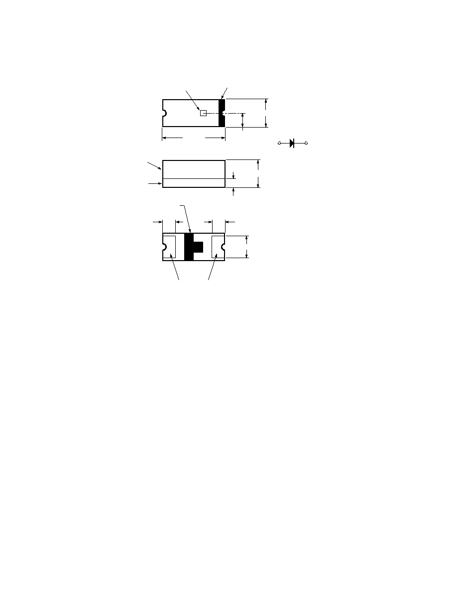
Package Dimensions
NOTES:
1. ALL DIMENSIONS IN MILLIMETERS (INCHES).
2. TOLERANCE IS ± 0.1 mm (± 0.004 IN.) UNLESS OTHERWISE SPECIFIED.
1.0 (0.04)
0.16 (0.006)
POLARITY
CATHODE
MARK
0.4 (0.016)
0.30 (0.012)
0.25 (0.01)
LED DIE
DIFFUSED
EPOXY
PC BOARD
SOLDERING
TERMINAL
0.5 (0.02)
0.4 (0.016) MIN.
0.30 (0.012)
CATHODE
LINE
3
Absolute Maximum Ratings at T
A
= 25∞C
Parameter
HSMA/C/L/T-C280
HSMG/D/S/Y-C280
Units
DC Forward Current
[1]
25
20
mA
Peak Pulsing Current
[2]
100
100
mA
Power Dissipation
75
52
mW
Reverse Voltage (I
R
= 100
µ
A)
5
5
V
LED Junction Temperature
95
95
∞C
Operating Temperature Range
≠30 to +85
≠30 to +85
∞C
Storage Temperature Range
≠40 to +85
≠40 to +85
∞C
Soldering Temperature
See IR soldering profile (Figure 7)
Notes:
1. Derate linearly as shown in Figure 4.
2. Pulse condition of 1/10 duty and 0.1 ms width.
Electrical Characteristics at T
A
= 25∞C
Forward Voltage
Reverse Breakdown
Capacitance C
Thermal
V
F
(Volts)
V
R
(Volts)
(pF), V
F
= 0,
Resistance
@ I
F
= 20 mA
@ I
R
= 100
µ
A
f = 1 MHz
R
J≠PIN
(∞C/W)
Part Number
Typ.
Max.
Min.
Typ.
Typ.
HSMA-C280
1.9
2.4
5
11
300
HSMC-C280
1.9
2.4
5
15
300
HSML-C280
1.9
2.4
5
20
300
HSMT-C280
1.9
2.4
5
15
300
HSMG-C280
2.2
2.6
5
9
250
HSMD-C280
2.2
2.6
5
7
250
HSMS-C280
2.1
2.6
5
5
250
HSMY-C280
2.1
2.6
5
6
250
Optical Characteristics at T
A
= 25∞C
Luminous
Color,
Viewing
Luminous
Intensity
Peak
Dominant
Angle
Efficacy
I
V
(mcd)
Wavelength
Wavelength
2
1/2
V
@ 20 mA
[1]
peak
(nm)
d
[2]
(nm)
Degrees
[3]
(lm/w)
Part Number
Color
Min.
Typ.
Typ.
Typ.
Typ.
Typ.
HSMA-C280
AS Amber
25
90
595
592
130
480
HSMC-C280
AS Red
25
90
637
626
130
155
HSML-C280
AS Orange
25
90
609
605
130
370
HSMT-C280
AS Deep Red
10
30
660
639
130
70
HSMG-C280
GaP Green
4.0
15
570
572
130
595
HSMD-C280
GaP Orange
2.5
8
605
604
130
380
HSMS-C280
HER
2.5
10
630
626
130
145
HSMY-C280
GaP Yellow
2.5
8
589
586
130
500
Notes:
1. The luminous intensity, I
V
, is measured at the peak of the spatial radiation pattern which may not be aligned with the mechanical axis of the lamp
package.
2. The dominant wavelength,
d
, is derived from the CIE Chromatically Diagram and represents the perceived color of the device.
3.
1/2
is the off-axis angle where the luminous intensity is 1/2 the peak intensity.
4
Note:
1. Bin categories are established for classification of products. Products
may not be available in all categories. Please contact your Agilent
representative for information on currently available bins.
Light Intensity (Iv) Bin Limits
[1]
Intensity (mcd)
Bin ID
Min.
Max.
A
0.11
0.18
B
0.18
0.29
C
0.29
0.45
D
0.45
0.72
E
0.72
1.10
F
1.10
1.80
G
1.80
2.80
H
2.80
4.50
J
4.50
7.20
K
7.20
11.20
L
11.20
18.00
M
18.00
28.50
N
28.50
45.00
P
45.00
71.50
Q
71.50
112.50
R
112.50
180.00
S
180.00
285.00
T
285.00
450.00
U
450.00
715.00
V
715.00
1125.00
W
1125.00
1800.00
X
1800.00
2850.00
Y
2850.00
4500.00
Note:
1. Bin categories are established for classifica-
tion of products. Products may not be avail-
able in all categories. Please contact your
Agilent representative for information on
currently available bins.
Tolerance:
±
15%
Color Bin Limits
[1]
Green Color Bins
[1]
Dom. Wavelength (nm)
Bin ID
Min.
Max.
A
561.5
564.5
B
564.5
567.5
C
567.5
570.5
D
570.5
573.5
E
573.5
576.5
Tolerance:
±
0.5 nm.
Orange Color Bins
[1]
Dom. Wavelength (nm)
Bin ID
Min.
Max.
A
597.0
600.0
B
600.0
603.0
C
603.0
606.0
D
606.0
609.0
E
609.0
612.0
F
612.0
615.0
Tolerance:
±
1 nm.
Yellow/Amber Color Bins
[1]
Dom. Wavelength (nm)
Bin ID
Min.
Max.
A
582.0
584.5
B
584.5
587.0
C
587.0
589.5
D
589.5
592.0
E
592.0
594.5
F
594.5
597.0
Tolerance:
±
0.5 nm.
5
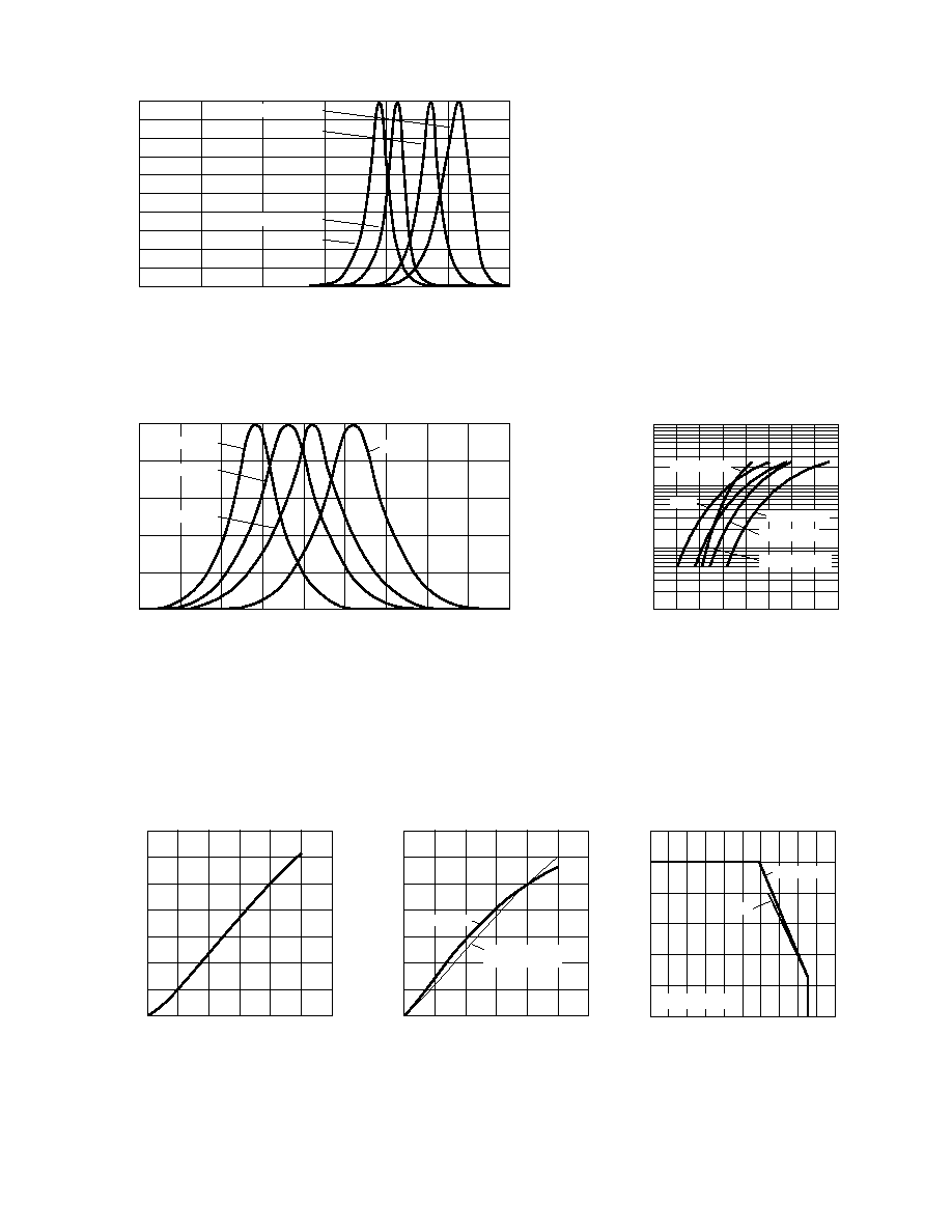
Figure 1b. Relative intensity vs. wavelength.
Figure 2. Forward current vs. forward voltage.
Figure 1a. Relative intensity vs. wavelength.
WAVELENGTH ≠ nm
RELATIVE INTENSITY
1.0
0
650
725
575
500
0.8
0.6
0.4
0.2
525
550
600
625
675
700
GaP ORANGE
HER
GaP YELLOW
GaP GREEN
100
10
1
0
1.5
1.7
1.9
2.1
2.3
VF ≠ FORWARD VOLTAGE ≠ V
I F
≠ FORWARD CURRENT ≠ mA
LPE GREEN
HER
1.6
1.8
2.0
2.2
AS AlInGaP
GaP YELLOW
GaP ORANGE
Figure 4. Maximum forward current vs.
ambient temperature.
Figure 3. Luminous intensity vs. forward current.
0
5
15
IF ≠ FORWARD CURRENT ≠ mA
0
0.4
1.0
LUMINOUS INTENSITY
(NORMALIZED AT 20 mA)
20
0.6
0.2
0.8
10
30
1.4
25
1.2
GaP
0
0
20
60
80
100
5
I F MAX.
≠ MAXIMUM FORWARD CURRENT ≠ mA
TA ≠ AMBIENT TEMPERATURE ≠ ∞C
40
15
30
10
20
GaP
25
AS AlInGaP
R
J-A = 600∞C/W
10
30
50
70
90
WAVELENGTH ≠ nm
RELATIVE INTENSITY
100
0
700
400
80
60
40
20
450
600
650
AS DEEP RED
550
500
90
70
50
30
10
AS RED
AS ORANGE
AS AMBER
0
5
15
IF ≠ FORWARD CURRENT ≠ mA
0
0.4
1.0
LUMINOUS INTENSITY
(NORMALIZED AT 20 mA)
20
0.6
0.2
0.8
10
30
1.4
25
1.2
AS AMBER
AS ORANGE, RED,
and DEEP RED