 | –≠–ª–µ–∫—Ç—Ä–æ–Ω–Ω—ã–π –∫–æ–º–ø–æ–Ω–µ–Ω—Ç: OPTA01 | –°–∫–∞—á–∞—Ç—å:  PDF PDF  ZIP ZIP |

4-47
5965-5937E
H
Programmable
Bar Code Decode ICs
Technical Data
HBCR-2210
HBCR-2211
Description
Hewlett-Packard's Bar Code
Decoder ICs offer flexible bar
code decoding capability that is
designed to give OEMs the ability
to address a growing number of
industry segments and applica-
tions. Flexibility is made possible
through sophisticated firmware
which allows the ICs to accept
data from a wide variety of
scanners and to automatically
recognize and decode the most
popular bar code symbologies.
User implementation of the
decoder ICs is easy since it
requires only a few supporting
components and provides a
standard I/O interface.
Manufacturers of data collection
terminals, point of sale terminals,
keyboards, weighing scales,
medical equipment, test instru-
mentation, material handling
equipment, and other systems
having data collection needs are
finding a growing demand for bar
code reading capability in their
products. The HBCR-2210 series
decode ICs make it easy to add
this capability without the need to
Features
∑ Ideal for Hand Scanning and
Non-contact Laser Scanning
Applications
∑ Supports 7 Industry
Standard Bar Code
Symbologies
∑ Automatic Code Recognition
∑ Choice of Parallel or Serial
Interface
∑ Full Duplex ASCII Interface
∑ Extensive Configuration
Control
∑ Optical and Escape
Sequence Configuration
∑ Input and Output Buffering
∑ Low Current (18 mA) CMOS
Technology
∑ 40 Pin DIP and 44 Pin PLCC
Packages
∑ Audio and Visual Feedback
Control
∑ EEPROM Support for
Nonvolatile Configuration
∑ Single +5 Volt Supply
invest in the development of bar
code decoding software.
The bar code decoder ICs are
compatible with most hand held
scanners and some medium
speed machine mounted laser
heads. The HBCR-2210 series is
compatible with fixed beam non-
contact scanners, digital wands,
and slot readers. In addition, the
decoder is optimized for use with
the Symbol Technologies moving
beam laser scanners, but is also
compatible with many other
moving beam non-contact laser
scanners with a similar interface
protocol.
The HBCR-2210 series decoder
ICs are excellent decoding solu

4-48
tions for a number of stationary
scanning applications found in
automated systems. The scan rate
for moving beam applications
should be similar to the scan
rates for hand held laser scanners
(35 to 45 scans per second). The
scan speed for fixed beam
applications should be similar to
the scan speeds typical of wands
and slot readers. For moving
beam applications, it is necessary
for the scanner to utilize the three
laser control lines.
The HBCR-2210 series decodes
the most popular bar code sym-
bologies now in use in applica-
tions in the industrial, retail,
government and medical markets:
∑ Code 39 (Standard or
Extended)
∑ Interleaved 2 of 5
∑ UPC A, E
∑ EAN/JAN 8, 13
∑ Codabar
∑ Code 128
∑ Code 11
∑ MSI Code
When more than one symbology
is enabled, the bar code being
scanned will automatically be
recognized and decoded, except
for Standard versus Extended
Code 39, which are mutually
exclusive. Bi-directional scanning
is allowed for all bar codes
except UPC/EAN/JAN with sup-
plemental digits, which must be
scanned with the supplemental
digits last.
The I/O for the decode IC is full
duplex, 7 bit ASCII. Both serial
and parallel interfacing are
available. The serial interface can
be converted to an RS232C
interface or connected directly to
another microprocessor for data
processing. The parallel interface
can be connected to a 74HC646
octal bus transceiver chip (or an
equivalent part). Feedback to the
operator is accomplished by
signals for an LED and a beeper.
In addition, there are many
programmable functions that
cover such items as code
selection, good read beep tone,
Header and Trailer buffers, laser
scanning control, beeper tone,
etc. See Table 2 for a complete
list.
Performance Features
Bar Codes Supported
Code 39 is an alphanumeric code,
while Extended Code 39 encodes
the full 128 ASCII character set
by pairing Code 39 characters.
Both can be read bi-directionally
with message lengths of up to 32
characters. An optional checksum
character can be used with these
codes, and the ICs can be config-
ured to verify this character prior
to data transmission.
Interleaved 2 of 5 code, a com-
pact numeric only bar code, can
also be read bi-directionally with
message lengths from 4 to 32
characters. To enhance data
accuracy, optional checksum
character verification and/or
message length checking can be
enabled.
The following versions of UPC,
EAN and JAN bar codes can be
read bi-directionally: UPC-A,
UPC-E, EAN-8, EAN-13, JAN-8,
and JAN-13. All versions can be
enabled simultaneously or
decoding can be restricted to
only the UPC codes. UPC, EAN,
and JAN codes printed with
complementary two or five digit
supplemental encodations can be
read in two different ways. If the
codes are enabled without the
supplemental encodations, then
only the main part of symbols
printed with supplemental
encodations will be read. If the
reading of supplemental
encodations is enabled, then only
symbols with these supplements
will be read. When supplemental
encodations are enabled, the bar
code symbols must be read in a
direction which results in the
supplements being scanned last.
Codabar, a numeric only bar code
with special characters, can be
read bi-directionally for message
lengths up to 32 characters. The
decode IC can be configured to
transmit or suppress the Codabar
start/stop characters.
Code 128, a full ASCII
symbology, can be scanned bi-
directionally with message
lengths of up to 32 characters.
Code 11 is a numeric, high
density code with one special
character, the hyphen (-).
Verification of one or two check
characters must be enabled, and
the check character(s) are always
transmitted. This code can be
scanned bi-directionally.
MSI Code is a numeric, continu-
ous code, with message lengths
up to 32 characters. The check
digit, a modulo 10 checksum, is
always verified and transmitted.
This code can be scanned bi-
directionally.
Scanner Input
The HBCR-2210 decode IC is
designed to accept data from
hand held digital scanners or slot
readers with the following logic
state: black = high, white = low.
The same decode IC also accepts

4-49
data from hand held laser
scanners with the opposite logic
states: black = low, white =
high. The scanner type pin (SCT)
on the HBCR-2210 series must be
driven prior to power up or hard
reset to identify the type of
scanner connected.
In the HBCR-2210 series ICs, the
automatic laser shutoff feature
delay time is adjustable as a con-
figuration option. Applications
which require increased accuracy
may need the redundancy check
feature.
Scanner input can be disabled by
software command. This allows
an application program to control
when an operator can enter data,
preventing inadvertent data entry.
It also allows the program to
verify each scan before enabling
subsequent scans. The HBCR-
2210 series also offers two Single
Read Modes which allow the
application program to stop bar
code data entry until a "Next
Read" command is received,
allowing the host computer to
process data transmissions before
enabling subsequent reads.
Configuration Control and
Non-volatile Storage
Configuration of the decoder IC
is done by any of three methods.
A minimal subset of key options
can be "hardwired" ≠ controlled
by electrically strapping specified
pins on the decoder IC itself.
Which pins affect configuration
depends on the selection of serial
or parallel interface. Alternatively,
ASCII characters in the form of
HP Escape Sequences (a format
common to HP decoder ICs) can
be sent to the serial or parallel
I/O port; these commands can be
used to control all configurable
options. A third method is optical
configuration, which makes use
of special bar code menus sup-
plied by HP. Menu labels can be
created to modify any configur-
able options. A summary of the
decoder IC features and
applicable configuration methods
for each is presented in Tables 2
and 3.
Once configuration has been set,
it can be stored in an optional
non-volatile memory, if included
in the decoder circuit. When the
EEP pin is tied high, the decoder
IC drives I/O lines compatible
with the widely available 9346/
93C46 family of serial EEPROMS.
The configuration is thereby
saved during power down of the
system and automatically
reloaded at power up. Escape
sequence commands allow
explicit storage and recall of
configuration settings. When
using optical configuration,
storage is automatic. If the EEP
pin is tied low, the EEPROM is
not used, so only hardwired
configuration options are saved
through powerdown; all others
are set to default values at
powerup. Table 2 shows default
values of all features.
Data Communications
The serial port supports a wide
range of baud rates, parities, and
stop bits as described in Table 2.
Software control of data trans-
mission can be accomplished
with a standard Xon/Xoff (DC1/
DC3) handshake. The decode IC
also supports an RTS/CTS
hardware handshake.
The parallel port data has config-
urable parity. When the SMD pin
is tied low, several pins pertain-
ing to the serial port change
function to control a parallel port
instead. Pins 1 through 5 on DIP
packages assume the function of
handshake lines for the parallel
port. The port itself is an external
'646 family octal bus transceiver.
Processor pins 10 and 11 (TXD
and RXD in serial mode) now
control the transceiver chip along
with pins 16 and 17, RD and WR.
Alternative circuits using SSI
latch chips can be substituted for
the '646 implementation to
customize the function of the
parallel port to a particular bus
configuration.
Feedback Features
Both audio and visual feedback
are possible with the HBCR-2210
series. In both cases, the outputs
from the ICs should be buffered
before driving the actual feed-
back transducer. An LED or
beeper connected to the decoder
IC can be controlled directly by
the IC, with signals generated by
successful decodes, or can be
controlled by the host system. In
addition, the tone of the beeper
can be configured to be one of 16
different frequencies, or can be
silenced.
Power Requirements
The decoder IC operates from a
+5 volt DC power supply. The
maximum current draw is 18 mA.
The maximum power supply
ripple voltage should be less than
100 mV, peak-to-peak.
Handling
Precautions
The decoder ICs are extremely
sensitive to electrostatic
discharge (ESD). It is important
that proper anti-static procedures
be observed when handling the
ICs. The package should not be

4-50
Table 1. Ordering Information
Part Number
Description
HBCR-2210
CMOS, 40 pin DIP, bulk ship, no manual
HBCR-2211
CMOS, 44 pin PLCC, bulk ship, no manual
OPT A01
IC individually boxed with manual and data sheet
HBCR-2297
HBCR-2210 Series Users Manual
Recommended Operating Conditions
Parameter
Symbol
Minimum
Maximum
Units
Notes
Supply Voltage
V
CC
4.0
6.0
V
1
Ambient Temperature
T
A
-40
+85
∞
C
Crystal Frequency
XTAL
0 (DC)
11.059
MHz
2
Element Time Interval
ETI
M
13
555
µ
s
2, 3, 4
(Moving Beam)
Element Time Interval
ETI
C
50
71000
µ
s
3, 4
(Contact Scanner)
Notes:
1. Maximum power supply ripple of 100 mV peak to peak.
2. The HBCR-2210 series uses a 11.059 MHz crystal. For different crystal frequencies. multiply the specified baud rate and beeper
frequencies by (crystal frequency/11.059 MHz) and multiply the element time interval ranges by (11.059 MHz/crystal frequency).
3. At the specified crystal frequency.
4. Corresponds to a scan rate of 35 to 45 scans per second.
Absolute Maximum Ratings
Parameter
Symbol
Minimum
Maximum
Units
Notes
Storage Temperature
T
S
-55
+150
∞
C
Supply Voltage
V
CC
-0.5
+7.0
V
5
Pin Voltage
V
IN
-0.5
V
CC
+ 0.5
V
5, 6
Notes:
5. T
A
= 25
∞
C.
6. Voltage on any pin with respect to ground.
opened except in a static free
environment.
Manuals
The decode IC Users Manual
covers the following topics:
∑ Data output formats
∑ I/O interfaces
∑ Laser input timing diagrams
∑ Escape sequence syntax and
functionality
∑ Example schematics
∑ All configurable options
∑ Bar code menus
∑ Scanner positioning and tilt
∑ Sample bar code symbols
∑ Appendices describing bar code
symbologies

4-51
DC Characteristics
HBCR-2210, 2211
(T
A
= 40
∞
C to +85
∞
C, V
CC
= 4.5 V to 5.5 V, V
SS
= 0 V)
Symbol
Parameter
HBCR-2210 Pins
HBCR-2211 Pins
Min.
Max.
Units
Test Conditions
V
IL
Input Low Voltage
all
all
-0.5
0.2 V
CC
V
- 0.1
V
IH
Input High Voltage
except 9, 18
except 10, 20
0.2 V
CC
V
CC
+ 0.5
V
+ 0.9
V
IH1
Input High Voltage
9, 18
10, 20
0.7 V
CC
V
CC
+ 0.5
V
V
OL
Output Low Voltage
1-8, 10-17, 21-28
2-9, 11, 13-19, 24-31
0.45
V
I
OL
= 1.6 mA
V
OL1
Output Low Voltage
30, 32-39
33, 36-43
0.45
V
I
OL
= 3.2 mA
V
OH
Output High Voltage
1-8, 10-17, 21-28
2-9, 11, 13-19, 24-31
2.4
V
I
OH
= -60
µ
A
0.75 V
CC
V
I
OH
= -30
µ
A
0.9
V
CC
V
I
OH
= -10
µ
A
V
OH
Output High Voltage
30, 32-39
33, 36-43
2.4
V
I
OH
= -400
µ
A
0.75 V
CC
V
I
OH
= -150
µ
A
0.9
V
CC
V
I
OH
= -40
µ
A
I
IL
Input Low Current
1-8, 10-17, 21-28
2-9, 11, 13-19, 24-31
-10
-200
µ
A
V
IN
= 0.45 V
I
IL2
Input Low Current
18
20
-3.2
mA
V
IN
= 0.45 V
I
LI
Input Leakage Current
32-39
36-43
±
10
µ
A
0.45
V
IN
V
CC
R
RST
Pulldown Resistor
9
10
20
125
K
I
CC
Power Supply
≠
≠
18
mA
All Outputs
Current
disconnected
I
CC
Idle Mode Power
≠
≠
9
mA
Note 7.
Supply Current
Note:
7. Applies only to HBCR-2210 and -2211 in Wand Mode or Laser Mode with Laser Idling enabled with no scanning or I/O operation in
progress.
Table 2. Summary of Features and Configurations - HBCR-2210 Series
In the table below, the column entitled Selection is either:
Software
Escape Sequence and Optical Menu Programmability
Hardwire
Control of a feature by electrically strapping specified pins on the decoder IC itself
Both
Both Software and Hardwire
Feature
Function or Value
Selection
Default Setting
Code Selection
When a symbology is enabled,
Both
Decoding of all
bar codes of that type can be
codes is enabled
read, assuming that other de-
coding options are satisfied.
Minimum/Maximum
Code 39, Codabar, Code 128,
Software
Min. = 1
Label Length
Code 11, and MSI Code
Max. = 32
Selection
Interleaved 2 of 5
Software
Min. = 4
Max. = 32
Interleaved 2 of 5
Length variable from 4 to 32,
Software
4 to 32
Specific Label
or a specific even length be-
Length Selection
tween 2 and 32, or lengths 6
and 14 only
(continued)

4-52
Feature
Function or Value
Selection
Default Setting
Check Character
For Code 39
Software
Disabled
Verification Enable
For Interleaved 2 of 5
Software
Disabled
When enabled, the check character
at the end of the bar code data
is verified by the decoder
Check Character
For both Code 39 and Interleaved
Software
Disabled
Transmission
2 of 5, the check characters
Enable
verified by the reader are
included at the end of the
decoded message
Code 39 Full ASCII
Extended Code 39 data will be
Software
Disabled
Conversion Enable
converted to ASCII characters
UPC/EAN/JAN
UPC/EAN/JAN vs. UPC only
Software
UPC/EAN/JAN
Decoding Options
Enable 2 or 5 digit supplements
Enabled
Selection
Supplements
Disabled
Autodiscrimination of tags with
Software
Disabled
and without supplements
Codabar Data
Transmit or suppress start/stop
Software
Transmit
Start/Stop
characters
Transmission Enable
Code 11 Check Digit
Selection of 1 or 2 check digits
Software
1 check digit
Verification Selection
Baud Rates
150, 300, 600, 1200, 2400,
Both
Depends on pins
4800, 9600, 19200
BR1, BR0, and SMD
Parity
0s, 1s, Odd, Even
Both
Depends on pins
EEP, PT1 and PT0
Stop Bits
1 or 2
Both
Depends on
pins SMD and STB
RTS/CTS Pacing
Request-To-Send/Clear-To-Send
Software
Enabled
Enable
Pacing controls serial port
data transmission
Xon/Xoff Pacing
Controls data transmission on
Software
Disabled
Enable
serial or parallel port by means
of control characters sent to
decoder IC
Transmitted Char-
Specifies whether a delay is
Software
Disabled
acter Delay Enable
inserted between characters
transmitted on the serial port
Transmitted Char-
Specifies the number of milli-
Software
20 msec
acter Delay
seconds to insert between
Selection
completion of transmission of
one character and beginning of
transmission of the next
(1 to 250 ms)
(continued)

4-53
Feature
Function or Value
Selection
Default Setting
Header Selection
A string of characters pre-
Software
none
pended to the decoded message
(10 characters, maximum)
Trailer Selection
A string of characters appended
Software
C
R
L
F
to the decoded message
(10 characters, maximum)
Reader Address
Reader Address is transmitted at
Software
none
Selection
the beginning of decoded and No-
Read messages for polling
purposes. (1 character)
Message Ready/Not
The Message Ready/Not Ready re-
Software
ACK/NAK
Ready Response
sponse is transmitted after the
Selection
reader receives a status request
type 3 and is used with Single
Read Mode 2. (1 character each)
No-Read Message
The No-Read Message configured
Software
none
Selection
is transmitted each time there
is an unsuccessful read
(10 characters, maximum)
No-Read
Controls whether the decoder
Software
Disabled
Recognition
detects unsuccessful reads
Enable
and sends the No-Read Message
Single Read Mode 1
Controls reading and automatic
Software
Disabled
Enable
transmission of decoded
messages
Single Read Mode 2
Controls separate reading of
Software
Disabled
Enable
bar codes and triggering decoded
message transmission
Output Buffering
Characters to be transmitted
Software
Disabled
Enable
are entered into a 256 character
queue for use with a pacing
protocol
Scanner Type
Determines whether a wand or
Hardwire
Depends on pin
Selection
laser is to be used
SCT
Laser Shutoff
Defines laser on time prior to
Software
3 seconds
Delay Selection
automatic shutoff, from 0 to 10
seconds in 100 ms steps
Laser Redundancy
Enables requirement for two
Software
Disabled
Check Enable
consecutive, identical decodes
for a good read
Continuous Laser
When enabled, the laser is turned
Software
Disabled
Read Mode Enable
on permanently instead of waiting
for the trigger to be pulled
(continued)

4-54
Feature
Function or Value
Selection
Default Setting
Laser Connection
When enabled, the scanner type
Software
Disabled
Detection Enable
pin is ignored at powerup.
Instead, the decoder tests for
a laser scanner to determine
scanner type
Laser Trigger
When enabled, the laser scanner
Software
Disabled
Latch Mode Enable
continues to scan after the
trigger has been released until
either the laser shutoff delay
period elapses or a read occurs
Laser Idling Enable
When enabled, the processor idles
Software
Disabled
while waiting for the trigger to
be pulled, reducing current draw
Code ID Character
Code ID character serves to
Software
Code 39 = a
Selection
identify the symbology of the
Int 2/5 =
b
decoded message
UPC/EAN = c
Codabar = d
Code 128 = e
Code 11 = f
MSI Code = g
Code ID Character
Code ID character can be added
Software
Disabled
Transmission
to the beginning of each decoded
Enable
message
Bar Code Menu
Verification of individual
Software
Disabled
Scan Response
configuration menu scans via
Enable
transmission of response message
Hard Reset
"Ready 12.4" C
R
L
F
will be
Software
Disabled
Message Enable
transmitted to host upon hard reset
ROM, RAM Self
When enabled, ROM and RAM are
Software
Enabled
Test Enable
tested after a Hard Reset
Good Read Beep
Selects Good Read Beep
Software
Tone 12
Tone Selection
tones (1 to 16)
LED Control
Controls the LED function:
Selection
Automatic Flash Mode
Enabled
Automatic Feedback Mode
Disabled
LED Active
Defines logic level of LED ON
Software
Active High
Level Selection
state
LED, Beeper Feed-
Suppresses LED and Beeper
Software
Not Suppressed
back Suppression
operation for systems without
Enable
those annunciators
Wand Input
Data from wand scans is collected
Software
Disabled
Buffering Enable
continuously in an input buffer
to increase throughput
Quiescent State of
The quiescent state of the pro-
Software
High
Address Line
cessor memory bus address lines
Selection
A8, A9, A10 can be defined for
additional I/O interfacing

4-55
Table 3. Summary of Commands - HBCR-2210 Series
Features
Description
Scanner Enable
When enabled, scans with the wand or laser are decoded; otherwise, they are
ignored
Hard Reset
Resets decoder IC as though it were just powered up
Soft Reset
Clears pacing conditions, errors
LED Control Selection
Controls the LED On/Off function
Status Requests
Cause the decoder to generate a status message
∑ General status message showing symbology of last message read, error
conditions, etc.
∑ Message Ready/Not Ready response (for Single Read Mode 2)
Sound Tone
This command causes the reader to sound a tone at the selected pitch for
approximately 100 milliseconds
Configuration Control
There are three operations that manipulate the decoder configuration as a block.
∑ Set default configuration
∑ Save configuration in non-volatile memory
∑ Recall non-volatile configuration
Execute Pending
For use with laser scanning, this command causes immediate execution of
Command
previous commands that would otherwise be postponed until the laser scan
finishes
Table 4. Summary of Other Features - HBCR-2210 Series
Power Idle Mode
Reduces current draw of processor from approximately 20 mA to 4 mA in
wand mode when the wand is inactive
Laser Failure Timeout
Turns off the laser if the Scan Sync signal is missing after approximately
1 second, and sets the laser failure status bit
Self Test Failure Message
An appropriate message is transmitted at power up if the decoder Self Test
fails.
∑ ROM SELF TEST FAILED
∑ EEPROM SELF TEST FAILED
∑ RAM SELF TEST FAILED
EEPROM Fault
An appropriate message is transmitted at power up if the EEPROM
Recognition
checksum is incorrect.
∑ EEPROM FAULT

4-56
Parallel Mode Handshake Timing
Figure 1. Host Commands Received by Decode IC (Reader).
Handshake Timing
t
CR
=
Falling edge of command ready to falling edge of command read. Max. = 30
µ
s for the first byte
of transmission from host.
t
CB
=
Falling edge of command read to command valid. Min. = 0
µ
s
t
CS
=
Command valid set up to rising edge of command ready. Min. = 0
µ
s
t
CA
=
Rising edge of command ready to rising edge of command read. Max. = 8
µ
s
t
CC
=
Rising edge of command read to falling edge of command ready. Min. = 0
µ
s
Handshake and Data Lines
Handshake and Data Lines
Figure 2. Decoder IC Data Sent to Host.
Handshake Timing
t
DO
= Falling edge of data ready to data output to bus. Min. = 6
µ
s
Typical Max. = 74
µ
s
Note: The maximum can be infinite if there is no data to be transmitted. RTS can be used to
determine when there is data. If the scanner is active or escape sequence commands
are being processed, (t
DO
= t
DF
) can extend by an indefinite amount.
t
DF
= Data output to bus to falling edge of data write. Max. = 6
µ
s
t
DA
= Falling edge of data write to rising edge of data ready. Min. = 0
µ
s
t
DW
= Rising edge of data ready to rising edge of data write. Max. = 8
µ
s
t
DH
= Data hold after rising edge of data write. Max. = 4
µ
s
t
DD
= Rising edge of data write to falling edge of data ready. Min. = 0
µ
s
CDY
CRD
PP0-PP7
tCA
tCS
tCB
tCR
tCC
RTS
DDY
PP0-PP7
tDD
tDF
tDO
DWR
tDA
tDW
tDH

4-57
PLCC Drying
Whenever Vapor Phase or Infra-
red Reflow Technologies are used
to mount the PLCC packages,
there is a possibility that
previously absorbed moisture,
heated very rapidly to the reflow
temperatures, may cause the
package to crack from the
internal stresses. There is a
reliability concern that moisture
may then enter the package over
a period of time, and metal
corrosion may take place,
degrading the IC performance.
To reduce the amount of
absorbed moisture and prevent
cracking, all of the PLCC ICs
should undergo one of the
Pin Definitions
Figure 3. HBCR-2210 Serial Pinout.
following baking cycles. The
parts must then be mounted
within 48 hours.
If the parts are not mounted with-
in 48 hours, they must be re-
baked.
The total number of baking cycles
must not exceed two. If the ICs
are baked more than twice,
Hewlett-Packard cannot guaran-
tee the performance and
reliability of the parts.
Neither bake cycle can be per-
formed in the standard shipping
tubes. The ICs must be baked in
an ESD safe, mechanically stable
container, such as an aluminum
tube or pan.
Cycle
Temperature
Time
Notes
A
125
∞
C
24 hrs
B
60
∞
C
96 hrs
8
Note:
8. Cycle B must be done in atmosphere of <5% relative
humidity air or nitrogen.
BR0
BR1
STB
CTS
RTS
LSE
SCT
TRG
RST
RxD
TxD
SDI
SSY
LED
BPR
WR
RD
XTAL 2
XTAL 1
VSS
VCC
AD0
AD1
AD2
AD3
AD4
AD5
AD6
AD7
EA + 5 V
ALE
NC
SMD + 5 V
EEP
EPC
ECE/PT1
EIO/PT0
A10
A9
A8
1
2
3
4
5
6
7
8
9
10
11
12
13
14
15
16
17
18
19
20
40
39
38
37
36
35
34
33
32
31
30
29
28
27
26
25
24
23
22
21
PIN MNEMONICS
ADDRESS/DATA BUS
RECEIVED DATA
TRANSMITTED DATA
BAUD RATE
PARITY
STOP BITS
LASER SCAN ENABLE
SCANNER TYPE
SCANNER DIGITAL INPUT
LED CONTROL LINE
BEEPER CONTROL LINE
DATA MEMORY WRITE
DATA MEMORY READ
CRYSTAL INPUT
CRYSTAL INPUT
SERIAL MODE SELECT
REQUEST TO SEND
CLEAR TO SEND
IC RESET
EEPROM SELECT
EEPROM CLOCK
EEPROM CHIP ENABLE
EEPROM I/O
LASER TRIGGER LINE
SCANNER SYNCHRONIZATION
ADDRESS LINE #8
ADDRESS LINE #9
ADDRESS LINE #10
EXTERNAL PROGRAM ENABLE
ADDRESS LATCH ENABLE
POWER
GROUND
AD0-AD7
RxD
TxD
BR0-BR1
PT0-PT1
STB
LSE
SCT
SDI
LED
BPR
WR
RD
XTAL1
XTAL2
SMD
RTS
CTS
RST
EEP
EPC
ECE
EIO
TRG
SSY
A8
A9
A10
EA
ALE
VCC
VSS
4-58
Figure 4. HBCR-2211 Serial Pinout.
Figure 5. HBCR-2210 Parallel Pinout.
LSE
6
5
4
3
2
1
44
43
42
41 40
SCT
TRG
RST
RxD
NC
TxD
SDI
SSY
LED
BPR
39
38
37
36
35
34
33
32
31
30
29
7
8
9
10
11
12
13
14
15
16
17
AD4
AD5
AD6
AD7
EA + 5 V
NC
ALE
NC
SMD + 5 V
EEP
EPC
18
19
20 21
22
23
24
25
26
27
28
RTS
CTS
STB
BR1
BR0
NC
V
CC
AD0
AD1
AD2
AD3
WR
RD
XTAL 2
XTAL 1
V
SS
NC
A8
A9
A10
PT0/EIO
PT1/ECE
PIN MNEMONICS
ADDRESS/DATA BUS
RECEIVED DATA
TRANSMITTED DATA
BAUD RATE
PARITY
STOP BITS
LASER SCAN ENABLE
SCANNER TYPE
SCANNER DIGITAL INPUT
LED CONTROL LINE
BEEPER CONTROL LINE
DATA MEMORY WRITE
DATA MEMORY READ
CRYSTAL INPUT
CRYSTAL INPUT
SERIAL MODE SELECT
REQUEST TO SEND
CLEAR TO SEND
IC RESET
EEPROM SELECT
EEPROM CLOCK
EEPROM CHIP ENABLE
EEPROM I/O
LASER TRIGGER LINE
SCANNER SYNCHRONIZATION
ADDRESS LINE #8
ADDRESS LINE #9
ADDRESS LINE #10
EXTERNAL PROGRAM ENABLE
ADDRESS LATCH ENABLE
POWER
GROUND
AD0-AD7
RxD
TxD
BR0-BR1
PT0-PT1
STB
LSE
SCT
SDI
LED
BPR
WR
RD
XTAL1
XTAL2
SMD
RTS
CTS
RST
EEP
EPC
ECE
EIO
TRG
SSY
A8
A9
A10
EA
ALE
VCC
VSS
CRD
CDY
DWR
DDY
RTS
LSE
SCT
TRG
RST
PGB
PDR
SDI
SSY
LED
BPR
WR
RD
XTAL 2
XTAL 1
VSS
VCC
AD0
AD1
AD2
AD3
AD4
AD5
AD6
AD7
EA + 5 V
ALE
NC
SMD 0 V
EEP
EPC
ECE/PT1
EIO/PT0
A10
A9
A8
1
2
3
4
5
6
7
8
9
10
11
12
13
14
15
16
17
18
19
20
40
39
38
37
36
35
34
33
32
31
30
29
28
27
26
25
24
23
22
21
PIN MNEMONICS
ADDRESS/DATA BUS
DATA WRITE HANDSHAKE
READY FOR DATA HANDSHAKE
COMMAND READ HANDSHAKE
COMMAND READY HANDSHAKE
PARITY
LASER SCAN ENABLE
SCANNER TYPE
SCANNER DIGITAL INPUT
LED CONTROL LINE
BEEPER CONTROL LINE
DATA MEMORY WRITE
DATA MEMORY READ
CRYSTAL INPUT
CRYSTAL INPUT
SERIAL MODE SELECT
TRANSCEIVER DRIVE ENABLE
TRANSCEIVER DIRECTION CONTROL
IC RESET
EEPROM SELECT
EEPROM CLOCK
EEPROM CHIP ENABLE
EEPROM I/O
LASER TRIGGER LINE
SCANNER SYNCHRONIZATION
ADDRESS LINE #8
ADDRESS LINE #9
ADDRESS LINE #10
EXTERNAL PROGRAM ENABLE
ADDRESS LATCH ENABLE
REQUEST TO SEND
POWER
GROUND
AD0-AD7
DWR
DDY
CRD
CDY
PT0-PT1
LSE
SCT
SDI
LED
BPR
WR
RD
XTAL1
XTAL2
SMD
PGB
PDR
RST
EEP
EPC
ECE
EIO
TRG
SSY
A8
A9
A10
EA
ALE
RTS
VCC
VSS

4-59
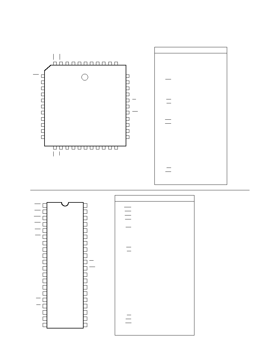
Figure 6. HBCR-2211 Parallel Pinout.
Figure 7. HBCR-2210 Mechanical Specifications.
LSE
6
5
4
3
2
1
44
43
42
41 40
SCT
TRG
RST
PGB
NC
PRD
SDI
SSY
LED
BPR
39
38
37
36
35
34
33
32
31
30
29
7
8
9
10
11
12
13
14
15
16
17
AD4
AD5
AD6
AD7
EA + 5 V
NC
ALE
NC
SMD + 0 V
EEP
EPC
18
19
20 21
22
23
24
25
26
27
28
RTS
DDY
DWR
CDY
CRD
NC
V
CC
AD0
AD1
AD2
AD3
WR
RD
XTAL 2
XTAL 1
V
SS
NC
A8
A9
A10
PT0/EIO
PT1/ECE
PIN MNEMONICS
ADDRESS/DATA BUS
DATA WRITE HANDSHAKE
READY FOR DATA HANDSHAKE
COMMAND READ HANDSHAKE
COMMAND READY HANDSHAKE
PARITY
LASER SCAN ENABLE
SCANNER TYPE
SCANNER DIGITAL INPUT
LED CONTROL LINE
BEEPER CONTROL LINE
DATA MEMORY WRITE
DATA MEMORY READ
CRYSTAL INPUT
CRYSTAL INPUT
SERIAL MODE SELECT
TRANSCEIVER DRIVE ENABLE
TRANSCEIVER DIRECTION CONTROL
IC RESET
EEPROM SELECT
EEPROM CLOCK
EEPROM CHIP ENABLE
EEPROM I/O
LASER TRIGGER LINE
SCANNER SYNCHRONIZATION
ADDRESS LINE #8
ADDRESS LINE #9
ADDRESS LINE #10
EXTERNAL PROGRAM ENABLE
ADDRESS LATCH ENABLE
REQUEST TO SEND
POWER
GROUND
AD0-AD7
DWR
DDY
CRD
CDY
PT0-PT1
LSE
SCT
SDI
LED
BPR
WR
RD
XTAL1
XTAL2
SMD
PGB
PDR
RST
EEP
EPC
ECE
EIO
TRG
SSY
A8
A9
A10
EA
ALE
RTS
VCC
VSS
52.8
51.9
40
21
1
20
14.2
13.6
15.7
14.9
5.1
MAX.
2.54
MAX.
0.3
MIN.
SEATING PLANE
2.54 ± 0.25
0.65 MAX.
0.6 MAX.
UNITS (mm)
0∞ ~ 15∞
INDEX
MARK
AREA

4-60
Figure 8. HBCR-2211 Mechanical Specifications.
Figure 9. System Block Diagram.
17.7
17.4
16.0
15.0
UNITS (mm)
16.7
16.5
39
29
17.7
17.4
16.7
16.5
40
6
28
18
7
17
INDEX MARK
1.32
1.22
0.81
0.66
0.53
0.33
16.0
15.0
4.57
4.20
0.51 MIN.
1
EE
PROM
HBCR-2210
SERIES
(OPT)
BAR CODE
INPUT
2K x 8
RAM
646
OR
(2)≠74HC574
LATCH
CONTROL
CONTROL
ADDRESS
ADDRESS
ADDRESS/
DATA
DATA
8
PARALLEL
PORT
(OPT)
SERIAL
PORT
(OPT)
DATA

4-61
Warranty and Service
The HP Bar Code Decode IC is
warranted for a period of one
year after purchase covering
defects in material and workman-
ship. Hewlett-Packard will repair
or, at its option, replace products
that prove to be defective in
material or workmanship under
proper use during the warranty
period.
NO OTHER WARRANTIES ARE
EXPRESSED OR IMPLIED,
INCLUDING BUT NOT LIMITED
TO THE IMPLIED WARRANTIES
OF MERCHANTABILITY AND
FITNESS FOR A PARTICULAR
PURPOSE. HEWLETT-PACKARD
IS NOT LIABLE FOR CONSE-
QUENTIAL DAMAGES.
For additional warranty or service
information please contact your
local Hewlett-Packard sales
representative or authorized
distributor.