 | –≠–ª–µ–∫—Ç—Ä–æ–Ω–Ω—ã–π –∫–æ–º–ø–æ–Ω–µ–Ω—Ç: PB4013B | –°–∫–∞—á–∞—Ç—å:  PDF PDF  ZIP ZIP |

*Request the AHA4013B Product Specification for complete details.
comtech aha corporation
comtech aha corporation
PRODUCT BRIEF*
AHA4013B
12.5 MBYTES/SEC REED-SOLOMON
ERROR CORRECTION DEVICE
The AHA4013B is a member of the AHA
PerFEC
TM
high performance, single-chip Reed-
Solomon Forward Error Correction (FEC) devices.
A single-phase clock synchronizes all chip
functions. CMOS technology and custom design
techniques help achieve the highest performance
and density. The AHA4013B implements a
standard polynomial approved by Intelsat and other
industry standards.
The device supports several programmable
parameters including block size, error threshold,
number of check bytes, order of output and mode of
operation. High operating frequency, input and
output rate flexibility, low processing latency and
various programmable parameters make this an
ideal part for many systems requiring Forward
Error Correction.
FEATURES
HIGH PERFORMANCE:
∑ Complies to Intelsat IESS-308, Revision 6B;
RTCA DO-217 Appendix F, Revision D and
proposed ITU-TS SG-18 (formerly CCITT SG-
18) Standards
∑ 50 MBytes/sec burst transfer rate with a 50 MHz
clock for all block lengths
∑ Sustained data transfer rates of 12.5 MBytes/sec
for block lengths from 54 bytes through 255 bytes
using a 50 MHz clock
∑ Processing latency time less than 12.2
µsec in
continuous mode for a block length of 100 bytes
FLEXIBILITY:
∑ Programmable to correct from 1 to 10 error bytes
or 20 erasure bytes per block
∑ Block lengths programmable from 3 to 255 bytes
∑ Decodes, encodes or passes data through
∑ Outputs corrected data or correction vectors in
forward or reverse order
∑ Continuous or burst mode operation
∑ Programmable error threshold to help determine
channel performance
SYSTEM INTERFACE:
∑ Simple system interface and internal buffers
eliminate external microprocessor and FIFOs
∑ Dedicated control pins permit discontinuities in
system data flow
OTHERS:
∑ 44 pin PLCC; 50 mil lead pitch
∑ Pin compatible with AHA4011 and AHA4012
∑ Plug compatible with AHA4011 and AHA4012
except for an initialization register setting
∑ Software emulation of the algorithm available
APPLICATIONS
∑ Satellite communications/VSAT/INTELSAT
∑ HDTV/DTV/CATV/DBS/ADSL
∑ Solid State Memory Systems
∑ Global Positioning Systems
∑ ISDN/T1/T3/OC1
∑ High Performance Modems
∑ Local/Wide Area Networks
6
5
4
3
2
1
44
43
42
41
40
DI
0
DI
1
DI
2
DI
3
DI
4
DI
5
DI
6
DI
7
DISN
CLK
GND
39
29
30
31
32
33
34
35
36
37
38
VDD
GND
GND
RDYON
RDYIN
DSON
ERASE
RSTN
VDD
GND
VDD
7
17
16
15
14
13
12
11
10
9
8
VDD
GND
GND
VDD
*NC
*NC
VDD
GND
GND
VDD
GND
18
19
20
21
22
23
24
25
26
27
28
DO0
DO1
DO2
DO3
DO4
DO5
DO6
VDD
DO7
ERR
CR
T
N
INPUT
OUTPUT
*NC = No connect, reserved for future considerations.
AHA4013B-050 PJC
YYWWD - COUNTRY OF ORIGIN
LLLLL
YYWWD = DATE CODE; LLLLL = LOT NUMBER

comtech aha corporation
FUNCTIONAL DESCRIPTION
This single-chip CMOS device can be operated
in encode, decode or pass-through mode.
The device is first initialized for various
programmable parameters including: erasure
multiplier, error threshold, number of check bytes,
number of message bytes per block, block length
and a control byte. Programming is done through
the input data bus DI[7:0]. This control byte defines
the format of the output data, such as, parity
information, error vectors, reverse or forward order,
normal or pass-through operations and conditions
for "uncorrectable" block. Following a six-byte
initialization, the device may be used to encode,
decode or pass-through data. The device requires
reinitialization when the parameters are changed or
when reset using the RSTN signal.
As an encoder, the device clocks input data
block followed by "dummy" check bytes
designated as "erasures" on the DI bus. ECC core
replaces the "dummy" check bytes with corrected
check bytes and feeds the block into the Output
Buffer for transfer out of the output bus, DO.
As a decoder, the device clocks the user data
and check bytes into the Input Buffer. The ECC
core performs the necessary corrections and feeds
the block to the Output Buffer.
In pass-through operation, the device clocks user
data and "dummy" check bytes into the Input Buffer.
The ECC core processes the block and transfers the
uncorrected input bytes into the Output Buffer. Data
is then made available on the output bus, DO.
The device can accept data input and generate
corrected data at a continuous rate as high as one
byte every 4 clocks. All rates lower than this are
also supported. I/O with the buffers can be done in
bursts at rates up to 50 MBytes/sec and up to one
block at a time. Data rates and latencies are
discussed further in a later section.
For every 2 check bytes, referred to as R, the
decoder can correct either 2 erasures or 1 error. An
erasure is an error with a known location and is
indicated by asserting the ERASE signal when the
erased byte is clocked into the AHA4013B.
The RS code implemented in the AHA4013B
uses the primitive polynomial:
to generate GF(256). The generator polynomial for
the code is:
These polynomials are specified by the Intelsat
IESS-308, Rev 6B; RTCA DO-217 Appendix F,
Rev D and proposed ITU-TS SG-18 standards.
AHA4013B DEVICE BLOCK DIAGRAM
TYPICAL APPLICATIONS DIAGRAM
P x
( )
x
8
x
7
x
2
x 1
+
+
+ +
=
G x
( )
x
i
≠
(
)
i
120
=
119 R
+
=
DI
INPUT BUFFER
ECC CORE
CONTROL
DO
367x9
OUTPUT BUFFER
256x9
REGISTER
RDYON
RSTN
DSIN
DSON
GND
VDD
CRTN
RDYIN
CLK
RDYIN
REGISTER
ERASE DI[7:0]
CLK
RSTN
DSIN
DSON
RDYON
CRTN
DO[7:0] ERR
VDD
GND
DATA SOURCE
AHA4013B
ECC COPROCESSOR
CHANNEL
1 TO x BITS WIDE
AHA4013B
ECC COPROCESSOR
DATA SINK
SYSTEM
CONTROLLER
SYSTEM
CONTROLLER
A
8
8
8
8
B
C
ENCODER
COMMUNICATIONS
DECODER
BLOCK FORMAT AT:
KDATA PLUS R "DUMMY" BYTES
KDATA PLUS R CHECK BYTES
KDATA BYTES
A
B
C

comtech aha corporation
SYMBOL (BYTE) ERROR RATE PERFORMANCE CURVES
The most common measures of performance
for Reed-Solomon code are P
SE
, P
UE
and C
BER
. P
SE
is the probability of symbol errors and is the ratio of
the number of received symbol errors to the total
number of received symbols. In the AHA4013B
device, a symbol is 8 bits. P
UE
is the probability of
an uncorrectable error and is the ratio of the number
of uncorrectable code blocks to the total number of
received code blocks. An uncorrectable error
occurs when more than t received symbols are in
error. C
BER
is the Corrected Bit Error Rate. The
C
BER
is the reciprocal of expected number of
correct bits between errors.
If input noise is random,
.
If
with
,
and
.
The figure shows probability of Symbol Error
and Uncorrectable Error for Block Size (N) of 255.
Error Rate Performance Curves for N=255
DATA RATES AND LATENCIES
Maximum processing latency in burst mode,
expressed in number of clocks, is
for forward order output. For C
i
less than or equal
to 1, use a value of 2 for C
i
. Table 1 presents burst
mode performance of the device.
Maximum latency in continuous mode is
where C
i
is the
number of input clocks/byte. The minimum clocks/
byte required for two different R values and various
message lengths are shown in Table 2.
IESS code lengths operated in continuous
mode are shown in Table 3.
CORRECTION TERMS
K- Number of user data symbols in one message
block.
R- Symbols appended to the user data to detect
and correct errors.
N- Sum of message and check symbols.
t - Maximum number of errors correctable by the
device.
Channel Rate - Transfer rate including user data
and error correction check bytes.
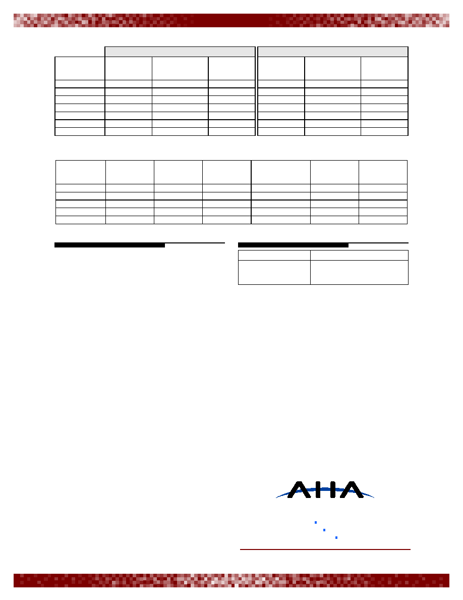
TABLE 1: BURST MODE OPERATION USING 50 MHz CLOCK AND 1 CLOCK/BYTE, FORWARD ORDER OUTPUT
C
BER
P
UE
m N
◊
---------------
=
P
SE
8 10
4
≠
◊
=
t
5
=
P
UE
10
7
≠
=
C
BER
10
7
≠
8 255
◊
------------------
4.9 10
11
≠
◊
=
=
10
-0
-3
10
-4
10
-5
10
-6
10
-7
10
-8
10
10
-1
10
-0
10
-2
-4
10
-6
10
-8
10
-10
10
-12
10
-14
10
-16
10
10
-2
P
UE
P
SE
t=1
t=3
t=5
t=8
t=10
N C
i
R 60 N
+
+
+
◊
N 1
≠
(
) C
i
R 60 N
C
i
C
i
1
≠
--------------
◊
+
+
+
◊
N
K R
+
=
t
Integer N K
≠
(
)
2
------------------------------------
=
CHECK BYTES `R' = 20
CHECK BYTES `R' = 2
BLOCK
LENGTHS `N'
MAXIMUM
LATENCY
(# of clocks)
MAXIMUM
LATENCY
(
µsecs)
AVERAGE RATE
(MBytes/sec)
MAXIMUM
LATENCY
(# of clocks)
MAXIMUM
LATENCY
(
µsecs)
AVERAGE RATE
(MBytes/sec)
25
155
3.10
8.06
137
2.74
9.13
50
230
4.60
10.88
212
4.24
11.79
100
380
7.60
13.13
362
7.24
13.75
150
530
10.64
14.13
512
10.24
14.63
200
680
13.60
14.75
662
13.28
15.13
255
845
16.88
15.13
827
16.56
15.38
comtech aha corporation
PB4013b_0905
© 2005 Comtech AHA Corp.
comtech aha corporation
1126 Alturas Drive
fax: 208.892.5601
tel: 208.892.5600
e-mail: sales@aha.com
Moscow, ID 83843-8331
A subsidiary of Comtech Telecommunications Corporation
www.aha.com
TABLE 2: CONTINUOUS MODE OPERATION USING 50 MHz CLOCK AND SPECIFIED CLOCKS/BYTE, FORWARD ORDER OUTPUT
TABLE 3: CONTINUOUS MODE OPERATION FOR IESS-308 CODES USING 50 MHz CLOCK AND SPECIFIED CLOCKS/BYTE,
FORWARD ORDER OUTPUT
ABOUT AHA
Comtech AHA Corporation (AHA) develops
and markets superior integrated circuits, boards,
and intellectual property core technology for
communications systems architects worldwide.
AHA has been setting the standard in Forward
Error Correction and Lossless Data Compression
technology for many years and provides flexible,
cost-effective solutions for today's growing
bandwidth and reliability challenges. Comtech
AHA Corporation is a wholly owned subsidiary of
Comtech Telecommuncations Corp. (NASDAQ:
CMTL). For more information, visit www.aha.com.
ORDERING INFORMATION
CHECK BYTES `R' = 20
CHECK BYTES `R' = 2
BLOCK
LENGTHS `N'
MINIMUM
REQUIRED
(clocks/byte)
MAXIMUM DATA
RATE
(MBytes/sec)
MAXIMUM
LATENCY
(
µsecs)
MINIMUM
REQUIRED
(clocks/byte)
MAXIMUM DATA
RATE
(MBytes/sec)
MAXIMUM
LATENCY
(
µsecs)
25
6
8.34
5.08
5
10.00
4.26
50
5
10.00
7.75
5
10.00
7.39
100
4
12.50
12.18
4
12.50
11.82
150
4
12.50
17.52
4
12.50
17.16
200
4
12.50
22.86
4
12.50
22.50
225
4
12.50
25.52
4
12.50
25.16
255
4
12.50
28.72
4
12.50
28.36
BLOCK
LENGTHS `N'
MESSAGE
LENGTH `K'
ERROR
CAPABILITY `t'
MINIMUM
REQUIRED
(clocks/byte)
MAXIMUM DATA
RATE
(MBytes/sec)
MAXIMUM
LATENCY
(# of clocks)
MAXIMUM
LATENCY
(
µ
secs)
126
112
7
4
12.50
742
14.84
194
178
8
4
12.50
1107
22.14
208
192
8
4
12.50
1181
23.62
219
201
9
4
12.50
1242
24.84
225
205
10
4
12.50
1276
25.52
PART NUMBER
DESCRIPTION
AHA4013B-050 PJC
12.5 MBytes/sec Reed-
Solomon Error Correction
Device - Commercial Temp