
LM385-2.5/LM385B-2.5
Micropower Voltage Reference
Analog Integrations Corporation 4F, 9 Industry E. 9th Rd, Science-Based Industrial Park, Hsinchu, Taiwan
DS-385C-01 012102
TEL: 886-3-5772500
FAX: 886-3-5772510
w ww.analog.com.tw
1
n
FEATURES
l
Operating Current from 20
µ
A to 20mA.
l
Low Temperature Coefficient.
l
1% and 2% Initial Tolerance.
l
Low Dynamic Impedance.
n
APPLICATIONS
l
Portable, Battery-Powered Equipment.
l
Instrumentation.
l
Process Control.
l
Energy Management.
l
Product Testing.
l
Automotive.
l
Precision Audio Components.
n
DESCRIPTION
The LM385-2.5 is a micropower 2-terminal band-
gap voltage reference, which can operate in a
20
µ
A to 20mA current range, they feature excep-
tionally low dynamic impedance and good tem-
perature stability. On-chip trimming is used to
achieve tight voltage tolerance. Since the LM385-
2.5 bandgap reference uses only transistors and
resistors, low noise and good long-term stability
result.
Careful design of the LM385-2.5 has made the de-
vice exceptionally tolerant of capacitive loading,
making it easy to use in almost any reference ap-
plication. The wide dynamic operating range al-
lows for its use with widely varying supplies with
excellent regulation.
The extremely low power drain of the LM385-2.5
makes it useful for micropower circuitry. This volt-
age reference can be used to make portable me-
ters, regulators, or general purpose analog circui-
try with battery life approaching shelf life. Further,
the wide operating current allows it to replace
older references with a tighter tolerance.
n
TYPICAL APPLICATION CIRCUIT
2.5V
+
R
S
V
IN
LM385-2.5
-
Precision 2.500V Voltage Reference

LM385-2.5/LM385B-2.5
2
n
ORDERING INFORMATION
PIN CONFIGURATION
1
2
3
SOT-89
TOP VIEW
1: NC
2: -
3: +
NC
+
NC
NC
-
NC
NC
NC
SO-8
TOP VIEW
1
2
3
TO-92
TOP VIEW
1: NC
2: +
3: -
SOT-23
TOP VIEW
1: -
2: +
3: NC
1
2
3
Example: LM385-2.5CSTR
ý
2% version, in SO-8 Package & Taping &
Reel Packing Type
(CS is not available in BAG packing type.)
LM385X-2.5CXXX
PACKING TYPE
BG: BAG
TB: TUBE (for SO-8)
TR: TAPE & REEL
PACKAGE TYPE
S : SMALL OUTLINE
U: SOT-23
X:
SOT-89
Z:
TO-92
TOLERANCE
Default: 2%
B: 1%
1
3
4
2
8
6
5
7
n
ABSOLUTE MAXIMUM RATINGS
Reverse Current ....... .................... ... ... ... ... ... ........................................................
30mA
Forward Current
... ... ... ....................................... .......... ... ... ... ..............................10mA
Operating Temperature Range.
.... ... ... ... ... ... ... ... ............... ... ......... ... ........ 0
∞
C to 70
∞
C
Storage Temperature ................................ ... ... ... ........ ... .........................
-65
∞
C to 150
∞
C
Lead Temperature
TO-92 Package Soldering (10 seconds)
..................... ... ... ... ... ... ... ... ...................
260
∞
C
SO Package Vapor phase (60 seconds) ............... ... ... ... ... ... ......... ... ...................
215
∞
C
n
TEST CIRCUIT
Refer to TYPICAL APPLICATION CIRCUIT.

LM385-2.5/LM385B-2.5
3
n
ELECTRICAL CHARACTERISTICS
(T
A
=25
∞
C, unless otherwise specified.)
PARAMETER
TEST CONDITIONS
SYMBOL
MIN.
TYP.
MAX.
UNIT
Reverse Breakdown Voltage
I
R
=100
µ
A
LM385B-2.5
LM385-2.5
V
R
2.475
2.450
2.500
2.500
2.525
2.550
V
20
µ
A
I
R
1mA
V
R
2
mV
Reverse Breakdown Voltage
Change with Current
1mA
I
R
20mA
V
R
20
mV
Reverse Dynamic Impedance I
R
=100
µ
A, f=20Hz
Z
R
1
Minimum Operating Current
I
RMIN
13
20
µ
A
Wideband Noise (rms)
I
R
=100
µ
A,
10Hz
f
10KHz
e
N
120
µ
Vrms
Average Temperature
Coefficient (Note)
I
R
=100
µ
A
V
R
100
ppm/
∞
C
Long Term Stability
I
R
=100
µ
A, T=1000Hrs,
T
A
=25
∞
C
V
R
/
t
20
ppm
Note : The average temperature coefficient is defined as the maximum deviation of reverse breakdown voltage
at all measured temperatures from T
MIN
to T
MAX
, divided by T
MAX
- T
MIN
. The measured temperatures are
0
∞
C, 25
∞
C, 50
∞
C and 70
∞
C.

LM385-2.5/LM385B-2.5
4
n
TYPICAL PERFORMANCE CHARACTERISTICS
Fig. 1 Reverse Characteristics
Reverse Current (
µ
A)
Reverse Voltage (V)
0.1
1
10
100
0
0.5
1
1.5
2
2.5
3
125
∞
C
25
∞
C
-25
∞
C
Fig. 2 Reverse Characteristics
Output Voltage Change (mV)
Reverse Current (mA)
0.01
0.1
1
10
100
0
2
4
6
8
-2
-25
∞
C
25
∞
C
80
∞
C
Fig. 3 Forward Characteristics
Forward Current (mA)
Forward Voltage (V)
0.01
0.1
1
10
100
0
0.2
0.4
0.6
0.8
1
1.2
1.4
125
∞
C
25
∞
C
-25
∞
C
Fig. 4 Response Time
Voltage Swing (V)
Time (
µ
S)
0
200
400
600
800
1000
0
0.5
1
1.5
2
2.5
12.5
100K
Output (1)
Input (2)
Output
Input
Fig. 5 Temperature Drift
Reference Voltage (V)
Temperature (
∞
C)
0
20
40
60
80
100
-20
2.48
2.49
2.5
2.51
2.52
Fig. 6 Noise Voltage (
nV Hz
/
)
Frequency (Hz)
Noise
100
1000
1000
10000
200
400
600
800
1000
LM385-2.5/LM385B-2.5
5
n
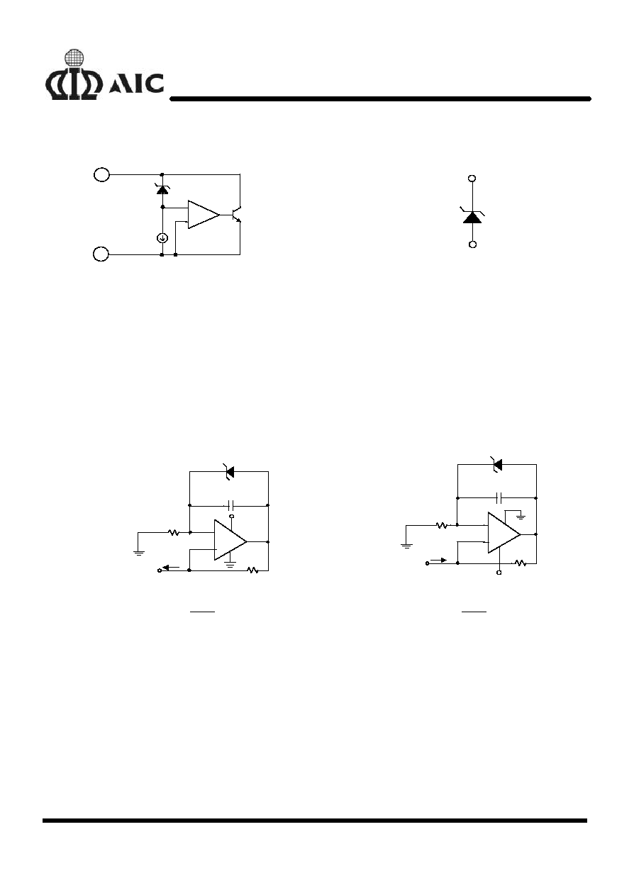
BLOCK DIAGRAM
n
SYMBOL
-
+
-
+
13
µ
A
2.5V
-
+
n
PIN DESCRIPTIONS
PIN +
- sinks current with a range from 20
µ
A to 20mA for normal applications. And a stable positive voltage,
relative to Pin-, occurs on Pin+.
PIN -
- Pin- sources current for normal application. The current value is the same as Pin+.
PIN NC - Not connected.
n
APPLICATION EXAMPLES
+
-
68K
LM385-2.5
1.5V to 27V
150pF
C1
30V
6
7
3
4
2
R1
R2
I
OUT
68K
LM385-2.5
-1.5V to -27V
150pF
C1
-30V
+
-
6
7
3
4
2
R1
R2
I
OUT
I
2 5V
R2
OUT
=
.
I
2 5V
R2
OUT
=
.
Fig. 7 Precision 1
µ
A to 1mA Current Source