 | –≠–ª–µ–∫—Ç—Ä–æ–Ω–Ω—ã–π –∫–æ–º–ø–æ–Ω–µ–Ω—Ç: AK2301A | –°–∫–∞—á–∞—Ç—å:  PDF PDF  ZIP ZIP |

ASAHI KASEI
AK2301A
<MS0300-E-00>
1
2004/3
AK2301A
3.3V Single channel
CODEC
GENERAL DESCRIPTION
The AK2301A is a single channel PCM CODEC
for speech processing 8kHz sampling PCM data by
DSP. The AK2301A interfaces with 14bit linear
data (16bit format).
It includes Band limiting filter, A/D and D/A
converter, and universal op-amps for construction
of the output filter. All functions are provided in
small 24pin VSOP package and it is good for
reducing the mounting space.
PACKAGE
- 24pin VSOP
Pin to pin 7.9mm x 7.6mm
Pin pitch 0.65mm
FEATURE
-
Single PCM CODEC and filtering systems
-
Mute function
-
PCM interface; 14bits linear data
(16bit format, serial interface)
-
Long Frame / Short Frame are selected
automatically
-
PCM data rate
256kHz/512kHz
- Op-Amp for the external gain adjustment
- Dual universal op-amps
- Single power supply voltage
+3.3±0.3V
- Low power consumption
- Small package
BLOCK DIAGRAM
AK2301A
CODEC Core
PCM I/F
AAF
SMF
BGREF
VDD
VSS
VREF
DX
DR
FS
BCLK
MUTEN
RSTN
TEST2
GST
VFTN
VFTP
VR
VFR
GSR
AMPT
AMPR
A/D
D/A
PLL
TAGND
PLLC
TEST1
TEST3
AMP1
AMP2
AMP1O
AMP1I
AMP2I
AMP2O
Internal
Main Clock

ASAHI KASEI
AK2301A
<MS0300-E-00>
2
2004/3
CONTENT
ITEMS PAGE
-
BLOCK DIAGRAM.......................................... 1
-
PIN CONDITION............................................. 3
-
PIN FUNCTION............................................... 4
-
ABSOLUTE MAXIMUM RATINGS..................... 5
-
RECOMMENDED OPERATING CONDITIONS...... 5
-
ELECTRICAL CHARACTERISTICS.....................5
-
PACKAGE INFORMATION............................... 10
-
PIN ASSIGNMENT.......................................... 11
-
MARKING...................................................... 11
-
CIRCUIT DESCRIPTION................................ 12
-
FUNCTIONAL DESCRIPTION........................... 13
-
PCM CODEC............................................ 13
-
PCM INTERFACE....................................... 14
-
Long Frame / Short Frame......................... 14
-
MUTE...................................................... 16
-
RESET SEQUENCE................................... 17
-
Universal op-amps.................................. 18
-
APPLICATION CIRCUIT EXAMPLE ................... 19

ASAHI KASEI
AK2301A
<MS0300-E-00>
3
2004/3
PIN CONDITION
Pin#
Name
I/O
Pin type
AC load
(MAX.)
DC load
(MIN.)
Output
status
(mute)
Remarks
15
VFTN
I
Analog
16
VFTP
I
Analog
14
GST
O
Analog
50pF
AC load
10k
(*1)
7
GSR
O
Analog
40pF
AC load
8k
(*1)
8
VFR
I
Analog
9
VR
O
Analog
40pF
AC load
8K
(*1)
Analog
ground
6
VDD
-
19
VSS
-
5
FS
I
CMOS
3
BCLK
I
CMOS
2
DX
O
CMOS
50pF
Hi-Z
4
DR
I
CMOS
23
MUTEN
I
CMOS
22
RSTN
I
CMOS
18
VREF
O
Analog
- External
capacitance
1.0
µ
F or more
20
PLLC
O
Analog
- External
capacitance
0.33
µ
F
±
4
(Includes
temperature
characteristic)
17
TAGND
O
Analog
- External
capacitance
1.0
µ
F or more
- 150uA load max
11
AMP2I
I
Analog
12
AMP1I
I
Analog
13
AMP1O
O
Analog
40pF
AC load
8k
(*1)
10
AMP2O
O
Analog
40pF
AC load
8k
(*1)
21
Test1
I
CMOS
- Tie to the VSS
24
Test2
I
CMOS
- Tie to the VSS
1
Test3
I
CMOS
- Tie to the VSS
*1) AC load is a load against AGND. This value includes a feedback resistance of input/output op -amp.

ASAHI KASEI
AK2301A
<MS0300-E-00>
4
2004/3
PIN FUNCTION
Pin types
NIN:
Normal input
TOUT: Try state output
AIN:
Analog input
AOUT: Analog output
PWR: Power / Ground
Pin# Name
Type
Function
15 VFTN
AIN
Neagative analog input of the transmit OP amp.
Diffelential or single amplifire is composed with the VFTP and the external
registers. Transmit gain is defined by the ratio of the external registers.
16
VFTP
AIN
Positive analog input of the transmit OP amp.
14 GST
AOUT
Output of the transmit OP amp.
The external feedback resister is connected between this pin and VFTP.
7 GSR
AOUT
Output of the receive OP amp.
Receive gain is defined by the ratio of the external registers.
The differential output can be composed with using the VR.
8 VFR
AIN
Negative analog input of the receive OP amp.
9 VR
AOUT Analog output of the D/A convertor equivalent to the received PCM code.
6 VDD
PWR
Positive supply voltage
+3.3V supply
19 VSS
PWR
Ground (0V)
5 FS
NIN
Frame sync input
This clock is input for the internal PLL which gerenates the internal system
clocks. FS must be 8kHz clock which synchronized with BCLK and do not stop
feeding.
3 BCLK
NIN
Bit clock of PCM data interface
This clock defines the input/output timing of DX and RX.
The frequency of BCLK should be 256kHz or 512kHz and do not stop feeding.
2 DX
TOUT
Serial output of PCM data
The PCM data is synchronized with BCLK. This output remains in the high
impedance except for the period in which PCM data is transmitted.
4 DR
NIN
Serial input of PCM data
The PCM data is synchronized with BCLK.
23 MUTEN
NIN
Mute setting pin
"L" level forces both A/D, D/A output to mute state.
22 RSTN
NIN
Reset signal input pin
Reset operation starts by low input. This pin is used for the initialization at the
power up. Please use MUTEN pin together to avoid the popping sound output
until the LSI finish the initialaization after the power up.Refer to P.13
18
VREF
AOUT
Analog ground output
External capacitance (1.0
µ
F or more) should be connected between this pin and
VSS.
Please do not connect external load to this pin.
20 PLLC
AOUT
PLL loop filter output
External capacitance (0.33
µ
F
±
40%: Includes temperature characteristic) should
be connected between this pin and VSS.
17 TAGND
AOUT
Analog ground output for transmitte OP amp
150uA load max. External capacitance (1.0
µ
F or more) should be connected
between this pin and VSS. This pin is used as an analog ground for transmit OP
amp (AMPT).
11
12
AMP1I
AMP2I
AIN
Negative input of the universal OP amp
13
10
AMP1O
AMP2O
AOUT
Output of the universal OP amp
21
24
1
TEST1
TEST2
TEAT3
NIN
Test pins
"H"=test mode
Please tie to VSS
ASAHI KASEI
AK2301A
<MS0300-E-00>
5
2004/3
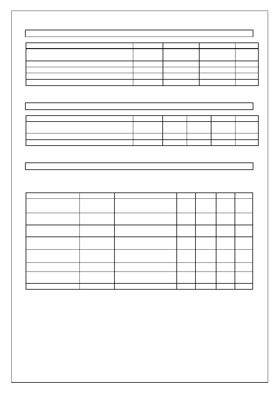
ABSOLUTE MAXIMUM RATINGS
Parameter
Symbol
Min
Max
Units
Power supply voltage
Analog/Digital power supply
VDD
-0.3
4.6
V
Digital input voltage
V
TD
-0.3
VDD+0.3
V
Analog input voltage
V
TA
-0.3
VDD+0.3
V
Input current (except power supply pins)
I
IN
-10
10
Storage temperature
Tstg
-55
125
Warnig: Exceeding absolute maximum ratings may causepermanent damage.
Normal operation is not guranteed at these extermes.
RECOMMENDED OPERATING CONDITIONS
Parameter
Symbol
Min
Typ
Max
Units
Power supply voltage
Analog/Digital power supply
VDD
3.0
3.3
3.6
V
Ambient operating temperature
Ta
-40
85
Frame sync frequency *)
FS
-1.0%
8
+1.0%
kHz
Note) All voltages reference to ground: VSS = 0V
*) All the characteristics of the CODEC is definied by 8kHz FS.
ELECTRICAL CHARACTERISTICS
Unless otherwise noted, guaranteed for VDD = +3.3V±0.3V, Ta = -40+85, FS=8kHz, VSS=0V
DC Characteristics
Parameter
Symbol
Conditions
Min
Typ
Max
Unit
Power Consumption
BCLK=512kHz
P
DD1
All output unloaded
*1)
10
15
mA
Output high voltage
V
OH
I
OH
-1.6mA
0.8VDD
V
Output low voltage
V
OL
I
OL
1.6mA
0.4
V
Input high voltage
VIH
0.7VDD
V
Input low voltage
VIL
0.3VDD
V
Input leakage current ILL
-10
+10
µ
A
Anarog ground output
voltage
VRG
1.4
1.5
1.6
V
Output leakage current ILT
Tri-state mode
-10
+10
µ
A
*1) VFTN/P=1020Hz@0dBm0 input, DR=1020Hz@0dBm0 Code input