 | –≠–ª–µ–∫—Ç—Ä–æ–Ω–Ω—ã–π –∫–æ–º–ø–æ–Ω–µ–Ω—Ç: AK6416AM | –°–∫–∞—á–∞—Ç—å:  PDF PDF  ZIP ZIP |

ASAHI KASEI
[AK6416A]
DAS02E-00
1999/05
- 1 -
AK6416A
16Kbit Serial CMOS EEPROM
Features
ADVANCED CMOS EEPROM TECHNOLOGY
READ/WRITE NON-VOLATILE MEMORY
- Wide Vcc (1.8V
5.5V) operation
- 16384 bits: 1024
’
16 organization
ONE CHIP MICROCOMPUTER INTERFACE
- Interface with one chip microcomputer's serial communication port directly
LOW POWER CONSUMPTION
- 0.8
µ
A Max (Standby mode)
HIGH RELIABILITY
-Endurance
: 100K cycles
-Data Retention
: 10 years
SPECIAL FEATURES
- High speed operation ( f
MAX
=4MHz: Vcc=4.5V
5.5V )
- Automatic write cycle time-out with auto-ERASE
- Automatic address increment (READ)
- Ready/Busy status signal
- Software and Hardware controlled write protection
IDEAL FOR LOW DENSITY DATA STORAGE
- Low cost, space saving, 8-pin package (SSOP)
Block diagram

ASAHI KASEI
[AK6416A]
DAS02E-00
1999/05
- 2 -
General Description
The AK6416A is a 16384bit, serial, read/write, non-volatile memory device fabricated using an advanced
CMOS EEPROM technology. The AK6416A has 16384bits of memory organized into 1024 registers of 16 bits
each. The AK6416A can operate full function under wide operating voltage range from 1.8V to 5.5V. The
charge up circuit is integrated for high voltage generation that is used for write operation.
The AK6416A can connect to the serial communication port of popular one chip microcomputer directly (3 line
negative clock synchronous interface). At write operation, AK6416A takes in the write data from data input pin
(DI) to a register synchronously with rising edge of input pulse of serial clock pin (SK). And at read operation,
AK6416A takes out the read data from a register to data output pin (DO) synchronously with falling edge of
SK.
The AK6416A has 4 instructions such as READ, WRITE, WREN (write enable) and WRDS (write disable).
Each instruction is organized by op-code block (8bits), address block (8bits) and data (8bits
’
2). When input
level of SK pin is high level and input level of chip select (CS) pin is changed from high level to low level,
AK6416A can receive the instructions.
Special features of the AK6416A include : automatic write time-out with auto-ERASE, Ready/Busy status
signal output and ultra-low standby power mode when deselected (CS=high).
∑
Software and Hardware controlled write protection
The AK6416A has 2 (hardware and software) write protection functions.
After power on or after execution of WRDS (write disable) instruction, execution of WRITE instruction will be
disabled. This write protection condition continues until WREN instruction is executed or Vcc is removed from
the part.
Execution of READ instruction is independent of both WREN and WRDS instructions.
Reset pin should be low level when WRITE instruction is executed. When the Reset pin is high level, the
WRITE instruction is not executed.
∑
Ready/Busy status signal
During the automatic write time-out period (BUSY status), the AK6416A can't accept the other instructions.
The AK6416A has 2 functions to know the Busy status from exterior.
The RDY/BUSY pin indicates the Busy status regardless of the CS pin status. The RDY/BUSY pin outputs the
low level regardless of the CS pin status during Busy status. Except the above status, this pin outputs high
level.
Also the DO pin indicates the Busy status. When input level of SK pin is low level and input level of CS pin is
changed from high level to low level, the AK6416A is in the status output mode and the DO pin indicates the
Ready/Busy status. The Ready/Busy status outputs on DO pin until CS pin is changed from low level to high
level, or first bit ("1") of op-code of next instruction is given to the part. Except when the device is in the status
output mode or outputs data, the DO pin is in the high impedance state.
,,
,,
,,
,,
Type of Products
Model
Memory size
Temp.Range
Vcc
Package
AK6416AM
16Kbits
-40
∞
C
85
∞
C
1.8V
5.5V
8pin Plastic SSOP
ASAHI KASEI
[AK6416A]
DAS02E-00
1999/05
- 3 -
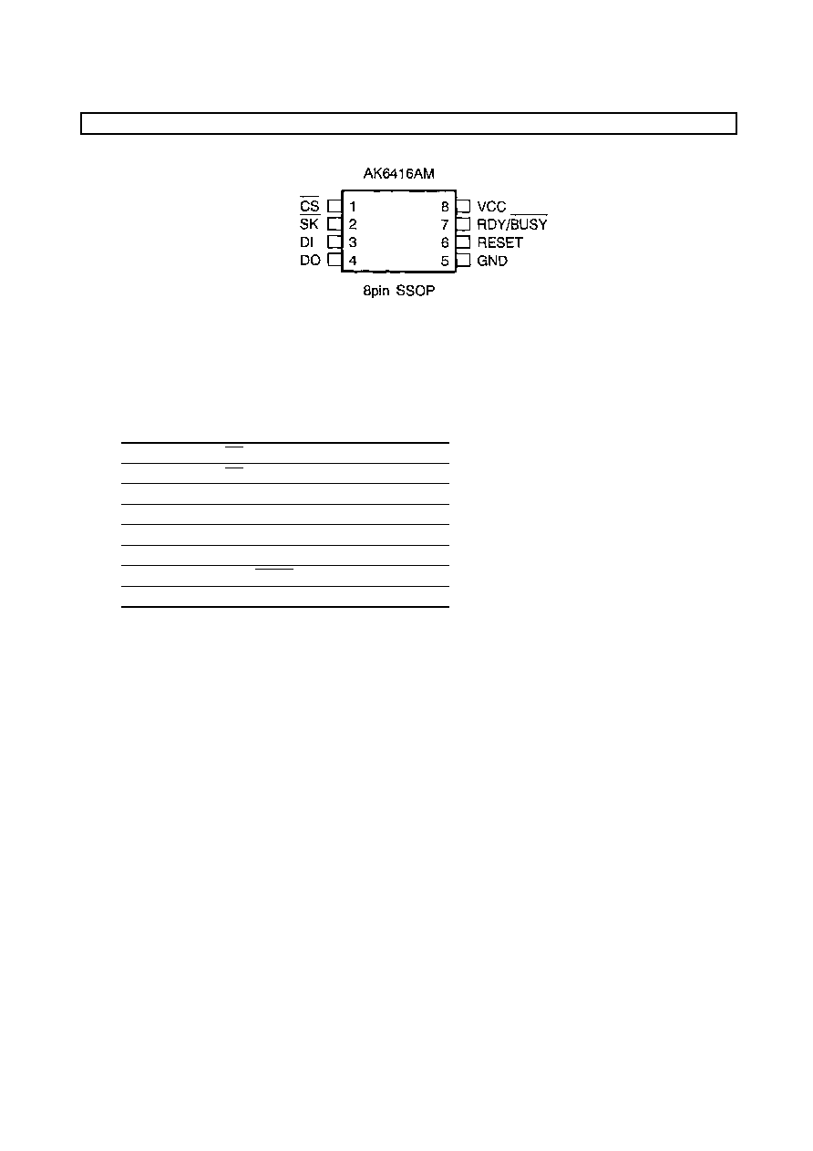
Pin arrangement
,,
,,
,,
,,
Pin Function
Pin No.
Pin name
I/O
1
CS
I
2
SK
I
3
DI
I
4
DO
O
5
GND
6
RESET
I
7
RDY/BUSY
O
8
Vcc
Note
I : Input pin
O : Output pin

ASAHI KASEI
[AK6416A]
DAS02E-00
1999/05
- 4 -
,,
,,
,,
,,
Pin Description
CS (Chip Select)
When SK is high level and CS is changed from high level to low level, AK6416A can receive the instructions.
CS should be kept low level while receiving op-code, address and data and while outputting data. If CS is
changed to high level during the above period, AK6416A stops the instruction execution. When SK is low and
CS is changed from high level to low level, AK6416A will be in status output mode. The CS need not be low
level during the automatic write time-out period (BUSY status).
SK (Serial Clock)
The SK clock pin is the synchronous clock input for input/output data. At write operation, AK6416A takes in
the write data from data input pin (DI) synchronously with rising edge of input pulse of serial clock pin (SK).
And at read operation, AK6416A takes out the read data to data output pin (DO) synchronously with falling
edge of SK. The SK clock is not needed during the automatic write time-out period (BUSY status), the status
output period and when the device isn't selected (CS = high level).
DI (Data Input)
The op-code, address and write data is input to the DI pin.
DO (Data Output)
The DO pin outputs the read data and status signal and will be high impedance except for this timing.
RDY/BUSY (Ready/Busy status)
This pin outputs the internal programming status. When the AK6416A is in the automatic write time-out
period, this pin outputs the low level (BUSY status), and outputs the high level except for this timing.
RESET (Reset)
The AK6416A stops executing the write instruction when the RESET pin is high level. The RESET pin should
be low level while the write instruction input period and the automatic write time-out period. If the RESET pin
is high level while the automatic write time-out period, the AK6416A stops execution of internal programming
and the device returns to ready status. In this case the word data of the specified address will be incomplete.
When inputting the new instruction after RESET, the CS pin should be set to high level. The read, write enable
and write disable instructions are not affected by RESET pin status.
Vcc (Power Supply)
GND (Ground)

ASAHI KASEI
[AK6416A]
DAS02E-00
1999/05
- 5 -
Functional Description
The AK6416A has 4 instructions such as READ, WRITE, WREN (write enable) and WRDS (write disable).
Each instruction is organized by op-code block (8bits), address block (8bits) and data (8bits
’
2). When input
level of SK pin is high level and input level of chip select (CS) pin is changed from high level to low level,
AK6416A can receive the instructions.
When the instructions are executed consecutively, the CS pin should be brought to high level for a minimum of
250ns(Tcs) between consecutive instruction cycle.
Instruction Set For 6416A
Instruction
Op-Code
Address
Data
WRITE
1 0 1 0 0 1 A9 A8
A7 A6 A5 A4 A3 A2 A1 A0
D15 -D0
READ
1 0 1 0 1 0 A9 A8
A7 A6 A5 A4 A3 A2 A1 A0
D15 -D0
WREN
1 0 1 0 0 0 1 1
’˝˝˝’˝˝˝’˝˝˝’˝˝˝’˝˝˝’˝˝˝’˝˝˝’
WRDS
1 0 1 0 0 0 0 0
’˝˝˝’˝˝˝’˝˝˝’˝˝˝’˝˝˝’˝˝˝’˝˝˝’
( WRAL )
1 0 1 0 1 1 1 1
’˝˝˝’˝˝˝’˝˝˝’˝˝˝’˝˝˝’˝˝˝’˝˝˝’
D15 -D0
’
:don't care
(Note) The WRAL instruction is used for factory function test only. User can't use this instruction .
Write
The write instruction is followed by 16 bits of data to be written into the specified address. After the 32nd
rising edge of SK to read D0 in, the AK6416A will be put into the automatic write time-out period. During the
automatic write time-out period (Busy status)and while entering write instruction, the RESET pin should be low
level. If the RESET pin is set to high level during the automatic write time-out period, the AK6416A stops
execution of internal programming and the device returns to ready status. In this case the word data of the
specified address will be incomplete. When inputting the new instructoin after RESET, the CS pin should be
set to high level. When inputting the new instruction after RESET, the CS pin should be set to high level.
When the RESET pin is kept at high level, the write is not executed. This becomes write protection function.
The CS pin need not be high level during automatic write time-out period (BUSY status).
WRITE

ASAHI KASEI
[AK6416A]
DAS02E-00
1999/05
- 6 -
Read
The read instruction is the only instruction which outputs serial data on the DO pin. When the 17th falling
edge of SK is received , the DO pin will come out of high impedance state and shift out the data from D15 first
in descending order which is located at the address specified in the instruction.
The data in the next address can be read sequentially by continuing to provide clock. The address
automatically cycles to the next higher address after the 16bit data shifted out. When the highest address is
reached ($3FF), the address counter rolls over to address $000 allowing the read cycle to be continued
indefinitely.
READ
WREN / WRDS ( Write Enable and Write Disable )
When Vcc is applied to the part, it powers up in the programming disable (WRDS) state. Programming must
be preceded by a programming enable (WREN) instruction. Programming remains enabled until a
programming disable (WRDS) instruction is executed or Vcc is removed from the part. The programming
disable instruction is provided to protect against accidental data disturb. Execution of a read instruction is not
affected by both WREN and WRDS instructions.
WREN/WRDS

ASAHI KASEI
[AK6416A]
DAS02E-00
1999/05
- 7 -
Absolute Maximum Ratings
Parameter
Symbol
Min
Max
Unit
Power Supply
VCC
-0.6
+7.0
V
All Input Voltages
with Respect to Ground
VIO
-0.6
VCC+0.6
V
Ambient storage temperature
Tst
-65
+150
∞
C
Stress above those listed under "Absolute Maximum Ratings" may cause permanent
damage to the device. This is a stress rating only and functional operation of the device at
these or any other conditions above those indicated in the operational sections of the
specification is not implied. Exposure to absolute maximum conditions for extended
periods may affect device reliability.
Recommended Operating Condition
Parameter
Symbol
Min
Max
Unit
Power Supply
VCC
1.8
5.5
V
Ambient Operating Temperature
Ta
-40
+85
∞
C

ASAHI KASEI
[AK6416A]
DAS02E-00
1999/05
- 8 -
Electrical Characteristics
(1) D.C. ELECTRICAL CHARACTERISTICS
( 1.8V
Vcc
5.5V, -40
∞
C
Ta
85
∞
C, unless otherwise specified )
Parameter
Symbol
Condition
Min.
Max.
Unit
ICC1
VCC=5.5V, tSKP=250ns, *1
5.5
mA
ICC2
VCC=2.5V, tSKP=500ns, *1
3.5
mA
Current Dissipation
(WRITE)
ICC3
VCC=1.8V, tSKP=1.0us, * 1
2.5
mA
ICC4
VCC=5.5V, tSKP=250ns, *1
1.5
mA
ICC5
VCC=2.5V, tSKP=500ns, *1
0.3
mA
Current Dissipation
(READ,WREN,
WRDS)
ICC6
VCC=1.8V, tSKP=1.0us, *1
0.2
mA
Current Dissipation
(Standby)
ICC
SB
VCC=5.5V *2
0.8
uA
Input High Voltage1
CS, SK, RESET pin
VIH1
1.8V
VCC
5.5V
0.8
’
VCC
VCC+0.5
V
VIH2
2.5V
VCC
5.5V
0.7
’
VCC
VCC+0.5
V
Input High Voltage2
DI pin
VIH3
1.8V
VCC<2.5V
0.8
’
VCC
VCC+0.5
V
Input Low Voltage1
CS, SK, RESET pin
VIL1
1.8V
VCC
5.5V
0
0.2
’
VCC
V
VIL2
2.5V
VCC
5.5V
0
0.3
’
VCC
V
Input Low Voltage2
DI pin
VIL3
1.8V
VCC<2.5V
0
0.2
’
VCC
V
VOH1
2.5V
VCC
5.5V
IOH=-50
µ
A
VCC-0.3
V
Output High Voltage
VOH2
1.8V
VCC<2.5V
IOH=-50
µ
A
VCC-0.3
V
VOL1
2.5V
VCC
5.5V
IOL=1.0mA
0.4
V
Output Low Voltage
VOL2
1.8V
VCC<2.5V
IOL=0.1mA
0.4
V
Input Leakage
ILI
VCC=5.5V,VIN=5.5V
`
1.0
uA
Output Leakage
ILO
VCC=5.5V
VOUT=5.5V,CS=VCC
`
1.0
uA
*1: VIN=VIH/VIL, DO=RDY/BUSY=Open
*2: CS=Vcc, SK/DI/RESET=Vcc/GND,DO=RDY/BUSY=Open

ASAHI KASEI
[AK6416A]
DAS02E-00
1999/05
- 9 -
(2) A.C. ELECTRICAL CHARACTERISTICS
( 1.8V
Vcc
5.5V, -40
∞
C
Ta
85
∞
C, unless otherwise specified )
Parameter
Symbol
Condition
Min.
Max.
Unit
tSKP1
4.5V
VCC
5.5V
250
ns
tSKP2
2.5V
VCC<4.5V
500
ns
SK Cycle Time
tSKP3
1.8V
VCC<2.5V
1.0
us
tSKW1
4.5V
VCC
5.5V
125
ns
tSKW2
2.5V
VCC<4.5V
250
ns
SK Pulse Width
tSKW2
1.8V
VCC<2.5V
500
ns
tCSS1
4.5V
VCC
5.5V
50
ns
CS Setup Time
tCSS2
1.8V
VCC<4.5V
100
ns
tCSH1
4.5V
VCC
5.5V
50
ns
CS Hold Time
tCSH2
1.8V
VCC<4.5V
100
ns
tSKSH/L1
4.5V
VCC
5.5V
50
ns
SK Setup Time
tSKSH/L2
1.8V
VCC<4.5V
100
ns
RESET Setup Time
tRESS
0
ns
RESET Hold Time
tRESH
0
ns
tDIS1
4.5V
VCC
5.5V
50
ns
tDIS2
2.5V
VCC<4.5V
100
ns
Data Setup Time
tDIS3
1.8V
VCC<2.5V
200
ns
tDIH1
4.5V
VCC
5.5V
50
ns
tDIH2
2.5V
VCC<4.5V
100
ns
Data Hold Time
tDIH3
1.8V
VCC<2.5V
200
ns
tPD1
4.5V
VCC
5.5V, *3
75
ns
tPD2
2.5V
VCC<4.5V, *3
150
ns
DO pin
Output delay
tPD3
1.8V
VCC<2.5V, *3
300
ns
RDY/BUSY pin
Output delay
tPD
CL=100pF
1
us
tE/W1
2.5V
VCC
5.5V
7
ms
Selftimed Programming
Time
tE/W2
1.8V
VCC<2.5V
10
ms
Write Recovery Time
tRC
100
ns
Min CS High Time
tCS
250
ns
DO High-Z Time
tOZ
500
ns
*3:CL=100pF

ASAHI KASEI
[AK6416A]
DAS02E-00
1999/05
- 10 -
Synchronous Data Timing
Instruction Input
Data Output (READ)

ASAHI KASEI
[AK6416A]
DAS02E-00
1999/05
- 11 -
Data Output (READ)
Ready / BUSY Signal Output(RDY/BUSY pin)

ASAHI KASEI
[AK6416A]
DAS02E-00
1999/05
- 12 -
Ready / BUSY Signal Output (DO pin)