 | –≠–ª–µ–∫—Ç—Ä–æ–Ω–Ω—ã–π –∫–æ–º–ø–æ–Ω–µ–Ω—Ç: 3121 | –°–∫–∞—á–∞—Ç—å:  PDF PDF  ZIP ZIP |
These Hall-effect switches are monolithic integrated circuits with
tighter magnetic specifications, designed to operate continuously over
extended temperatures to +150
∞C, and are more stable with both tem-
perature and supply voltage changes. The unipolar switching character-
istic makes these devices ideal for use with a simple bar or rod magnet.
The three basic devices (3121, 3122, and 3123) are identical except for
magnetic switch points.
Each device includes a voltage regulator for operation with supply
voltages of 4.5 voltas to 24 volts, reverse battery protection diode,
quadratic Hall-voltage generator, temperature compensation circuitry,
small-signal amplifier, Schmitt trigger, and an open-collector output to
sink up to 25 mA. With suitable output pull up, they can be used with
bipolar or CMOS logic circuits. The 3121 is an improved replacement
for the 3113 and 3119.
The first character of the part number suffix determines the device
operating temperature range. Suffix `E≠' is for the automotive and
industrial temperature range of -40
∞C to +85∞C. Suffix `L≠' is for the
automotive and military temperature range of -40
∞C to +150∞C. Three
package styles provide a magnetically optimized package for most
applications. Suffix `≠LT' is a miniature SOT-89/TO-243AA transistor
package for surface-mount applications; suffix `≠U' is a three-lead
plastic mini-SIP while suffix `≠UA' is a three-lead ultra-mini-SIP.
HALL-EFFECT SWITCHES
FOR HIGH-TEMPERATURE OPERATION
Always order by complete part number, e.g., A3121EU .
ABSOLUTE MAXIMUM RATINGS
at T
A
= +25
∞
C
Supply Voltage, V
CC
........................... 30 V
Reverse Battery Voltage, V
RCC
........ -30 V
Magnetic Flux Density, B ....... Unlimited
Output OFF Voltage, V
OUT
................ 28 V
Reverse Output Voltage, V
OUT
........ -0.5 V
Continuous Output Current, I
OUT
... 25 mA
Operating Temperature Range, T
A
Suffix `E≠' ................. -40
∞
C to +85
∞
C
Suffix `L≠' ............... -40
∞
C to +150
∞
C
Storage Temperature Range,
T
S
.............................. -65
∞
C to +170
∞
C
FEATURES and BENEFITS
I Superior Temp. Stability for Automotive or Industrial Applications
I 4.5 V to 24 V Operation ... Needs Only An Unregulated Supply
I Open-Collector 25 mA Output ... Compatible with Digital Logic
I Reverse Battery Protection
I Activate with Small, Commercially Available Permanent Magnets
I Solid-State Reliability ... No Moving Parts
I Small Size
I Resistant to Physical Stress
Data
Sheet
27621.4B
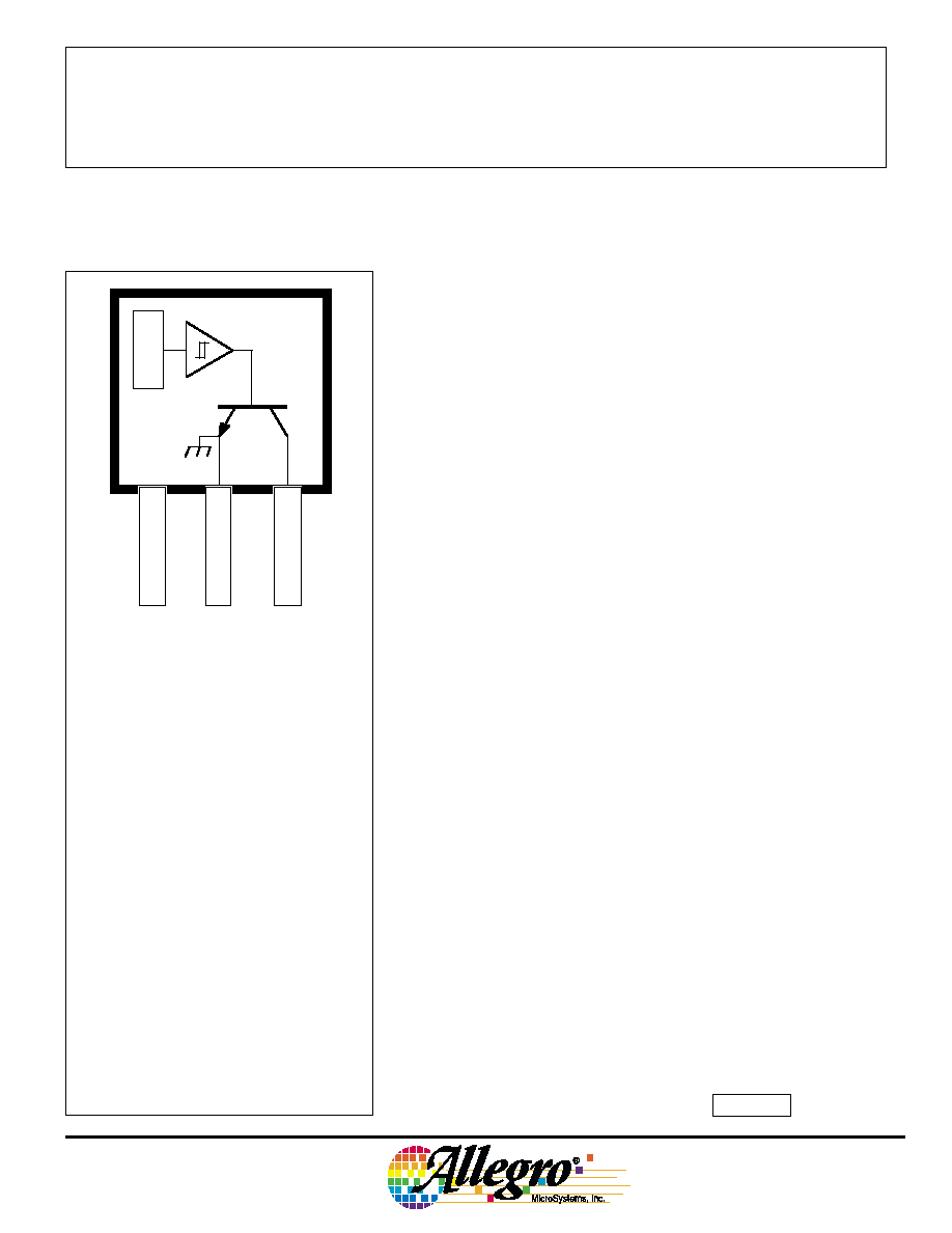
Pinning is shown viewed from branded side.
3121, 3122,
AND
3123
Dwg. PH-003A
1
SUPPLY
V
CC
GROUND
3
2
OUTPUT
X
3121, 3122,
AND
3123
HALL-EFFECT SWITCHES
FOR HIGH-TEMPERATURE
OPERATION
115 Northeast Cutoff, Box 15036
Worcester, Massachusetts 01615-0036 (508) 853-5000
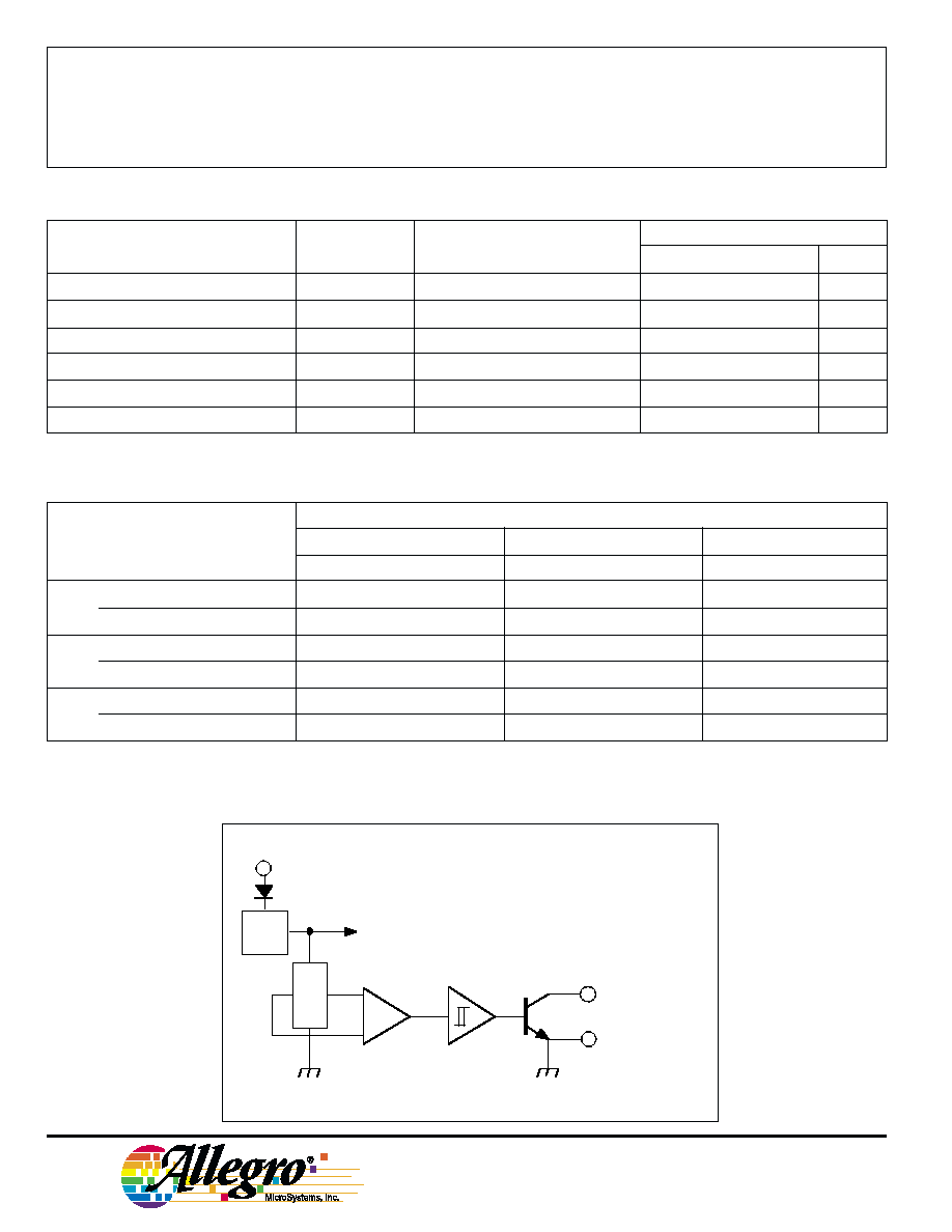
FUNCTIONAL BLOCK DIAGRAM
Limits
Characteristic
Symbol
Test Conditions
Min.
Typ.
Max.
Units
Supply Voltage
V
CC
Operating
4.5
--
24
V
Output Saturation Voltage
V
OUT(SAT)
I
OUT
= 20 mA, B > B
OP
--
14040
0 mV
Output Leakage Current
I
OFF
V
OUT
= 24 V, B < B
RP
--
<1.010
µA
Supply Current
I
CC
B < B
RP
(Output OFF)
--
4.6
9.0mA
Output Rise Time
t
r
R
L
= 820
, C
L
= 20 pF
--
0.04
2.0
µs
Output Fall Time
t
f
R
L
= 820
, C
L
= 20 pF
--
0.18
2.0
µs
ELECTRICAL CHARACTERISTICS over operating temperature range, at V
CC
= 12 V.
MAGNETIC CHARACTERISTICS in gauss over operating supply voltage range.
Part Numbers*
A3121
A3122
A3123
Characteristic
Min.
Typ.
Max.
Min.
Typ.
Max.
Min.
Typ.
Max
B
OP
at T
A
= 25
∞C
250350450
28034040
0
250345
440
over operating temp. range
22035050
0
260340430
230345
470
B
RP
at T
A
= 25
∞C
125
245
380
140235
330
18024030
0
over operating temp. range
80245
410
120235
360
160240330
B
hys
at T
A
= 25
∞C
7010
5
140
7010
5
140
7010
5
140
over operating temp. range
6010
5
150
7010
5
140
7010
5
140
NOTES: Typical values are at T
A
= +25
∞C and V
CC
= 12 V.
B
OP
= operate point (output turns ON); B
RP
= release point (output turns OFF); B
hys
= hysteresis (B
OP
- B
RP
).
*Complete part number includes a suffix to identify operating temperature range (E- or L-) and package type ( -LT, -U, or -UA).
V
CC
X
REG.
Dwg. FH-005-2
GROUND
OUTPUT
3
2
1
Copyright © 1992, 1999, Allegro MicroSystems, Inc.
3121, 3122,
AND
3123
HALL-EFFECT SWITCHES
FOR HIGH-TEMPERATURE
OPERATION
SWITCH POINTS
OUTPUT SATURATION VOLTAGE
* Complete part number includes a suffix denoting operating temperature range (E- or L-) and package type ( -LT, -U, or -UA).
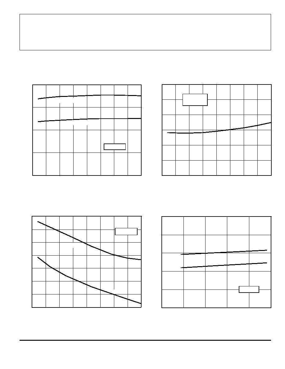
TYPICAL OPERATING CHARACTERISTICS
0
50
100
AMBIENT TEMPERATURE IN ∞C
-50
Dwg. GH-038
SWITCH POINT IN GAUSS
300
400
200
100
OPERATE POINT
RELEASE POINT
V = 12 V
CC
150
0
-25
25
75
125
0
25
50
75
100
0
0
AMBIENT TEMPERATURE IN ∞C
0
0
-50
Dwg. GH-040
150
-25
125
I = 20 mA
V = 4.5≠24 V
OUT
CC
0
25
50
75
100
AMBIENT TEMPERATURE IN ∞C
-50
Dwg. GH-039
125
-25
V = 12 V
CC
SUPPLY CURRENT IN mA
7.0
6.0
5.0
4.0
150
B
B
RP
B
B
OP
10
15
20
25
SUPPLY VOLTAGE IN VOLTS
0
Dwg. GH-041
5
SUPPLY CURRENT IN mA
0
2.0
4.0
6.0
8.0
10
B
B
OP
B
B
RP
T = +25∞C
A
SUPPLY CURRENT
SUPPLY CURRENT
3121, 3122,
AND
3123
HALL-EFFECT SWITCHES
FOR HIGH-TEMPERATURE
OPERATION
115 Northeast Cutoff, Box 15036
Worcester, Massachusetts 01615-0036 (508) 853-5000
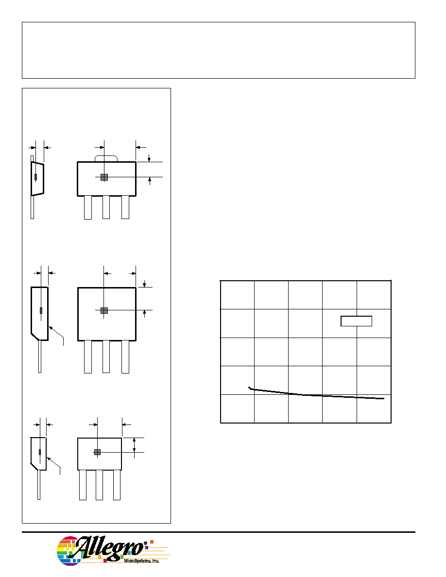
SENSOR LOCATIONS
(
±0.005" [0.13 mm] die placement)
OPERATION
The output of these devices (pin 3) switches low when the mag-
netic field at the Hall sensor exceeds the operate point threshold (B
OP
).
At this point, the output voltage is V
OUT(SAT)
. When the magnetic field
is reduced to below the release point threshold (B
RP
), the device output
goes high. The difference in the magnetic operate and release points is
called the hysteresis (B
hys
) of the device. This built-in hysteresis allows
clean switching of the output even in the presence of external mechani-
cal vibration and electrical noise.
APPLICATIONS INFORMATION
Hall effect applications information is available in the "Hall-Effect
IC Applications Guide", which can be found in the latest issue of
Allegro MicroSystems Data Book AMS-702.
CHANGE IN OPERATE POINT
Suffix "LT"
Suffix "U"
Suffix "UA"
0.043"
1.09 mm
1
3
2
Dwg. MH-008-2C
0.030"
0.76 mm
NOM
ACTIVE AREA DEPTH
0.089"
2.26 mm
A
1
3
2
Dwg. MH-002-2B
0.016"
0.41 mm
NOM
BRANDED
SURFACE
ACTIVE AREA DEPTH
0.070"
1.78 mm
A
0.091"
2.31 mm
1
3
2
Dwg. MH-011-2C
0.019"
0.48 mm
NOM
BRANDED
SURFACE
ACTIVE AREA DEPTH
0.082"
2.07 mm
0.055"
1.38 mm
A
10
15
20
25
SUPPLY VOLTAGE IN VOLTS
0
Dwg. GH-042
5
CHANGE IN OPERATE POINT IN GAUSS
-5.0
0
5.0
10
15
20
T = +25∞C
A
3121, 3122,
AND
3123
HALL-EFFECT SWITCHES
FOR HIGH-TEMPERATURE
OPERATION
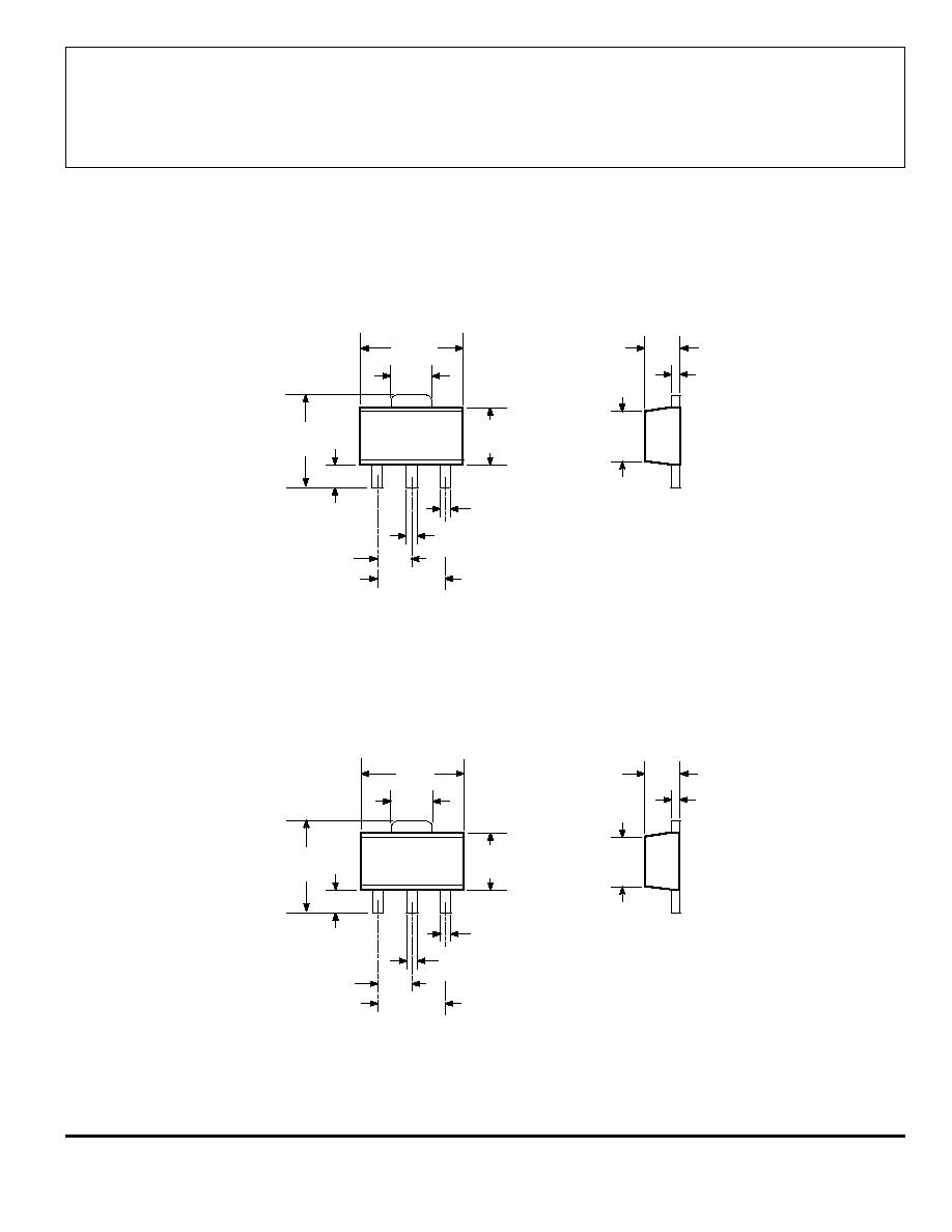
PACKAGE DESIGNATOR `LT'
Dimensions in Inches
(for reference only)
Dimensions in Millimeters
(controlling dimensions)
Dwg. MA-009-3 in
1
2
3
0.064
0.072
0.155
0.167
0.059
BSC
0.014
0.019
0.035
0.047
0.090
0.102
0.055
0.063
0.014
0.017
0.084
0.090
0.017
0.022
0.118
BSC
0.173
0.181
Dwg. MA-009-3 mm
1
2
3
4.40
4.60
1.62
1.83
3.94
4.25
1.50
BSC
0.36
0.48
0.89
1.20
2.29
2.60
1.40
1.60
0.35
0.44
2.13
2.29
0.44
0.56
3.00
BSC
NOTE: Exact body and lead configuration at vendor's option within limits shown.