
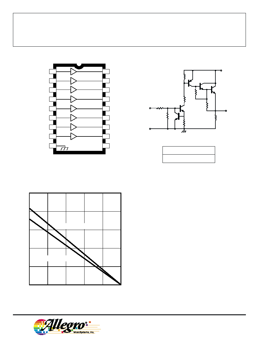
Consisting of eight npn Darlington output stages and the associ-
ated common-emitter input stages, these drivers are designed to
interface between low-level digital logic and vacuum fluorescent
displays. Both devices are capable of driving the digits and/or seg-
ments of these displays and are designed to permit all outputs to be
activated simultaneously. Pull-down resistors are incorporated into
each output and no external components are required for most fluores-
cent display applications.
With any device, the output load is activated when the input is
pulled towards the positive supply (active `high'). The UDN6118A is
furnished in a standard 18-pin plastic DIP; the A6118SLW is in a 20-
lead wide-body SOIC. Both units operate over the temperature range
of -20
∞C to +85∞C. These devices are also available for operation over
the temperature range of -40
∞C to +85∞C by changing the part number
to UDQ6118A or A6118ELW.
FEATURES
I Digit or Segment Drivers
I Low Input Current
I Integral Output Pull-Down Resistors
I High Output Breakdown Voltage
I Single or Split Supply Operation
I Automotive Capable
Always order by complete part number, e.g., UDN6118A .
ABSOLUTE MAXIMUM RATINGS
at T
A
= +25
∞
C
Supply Voltage, V
BB
. . . . . . . . . . . . . . . 85 V
Input Voltage, V
IN
. . . . . . . . . . . . . . . . . 20 V
Output Current, I
OUT
. . . . . . . . . . . . -40 mA
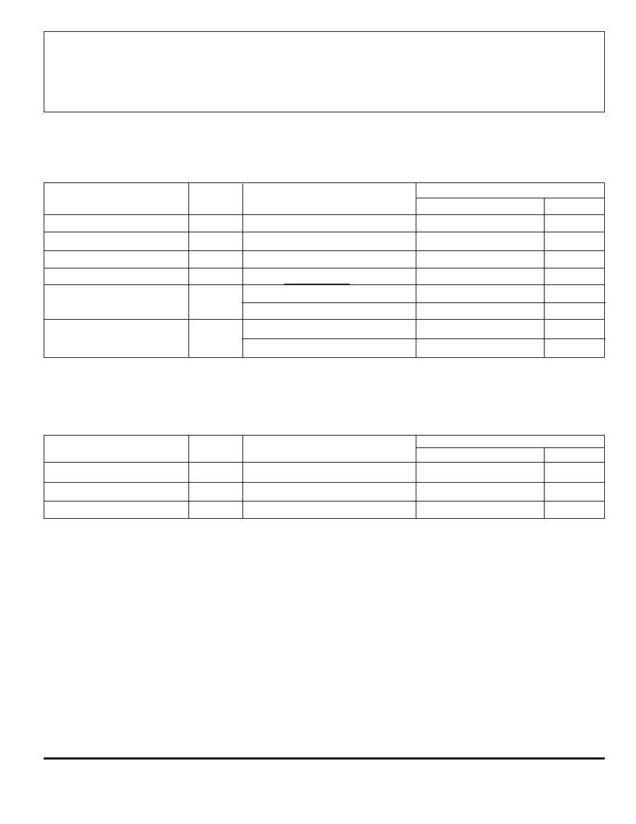
Allowable Package Power Dissipation,
P
D
. . . . . . . . . . . . . . . . . . . . See Graph
Operating Temperature Range,
T
A
. . . . . . . . . . . . . . . . . -20
∞
C to +85
∞
C
Storage Temperature Range,
T
S
. . . . . . . . . . . . . . . -55
∞
C to +150
∞
C
Caution: The high input impedance of these
devices makes them susceptible to static
discharge damage associated with handling and
testing. Techniques similar to those used for
handling MOS devices should be employed.
Data Sheet
29313D*
A6118SLW
13
14
15
16
17
19
12
18
20
11
1
2
3
8
9
4
5
6
7
10
NC
NC
Dwg. PP-064-3
V
BB
VACUUM FLUORESCENT
DISPLAY DRIVER
6118
6118
VACUUM FLUORESCENT
DISPLAY DRIVER
115 Northeast Cutoff, Box 15036
Worcester, Massachusetts 01615-0036 (508) 853-5000
PARTIAL SCHEMATIC
ONE DRIVER (ALL TYPES)
INPUT
GND
15K
OUTPUT
30K
27K
125K
R
IN
R
B
V
BB
UDN6118A
R
IN
R
B
10 k
30 k
Dwg. No. A-10,592C
50
75
100
125
150
2.5
0.5
0
ALLOWABLE PACKAGE POWER DISSIPATION IN WATTS
AMBIENT TEMPERATURE IN
∞C
2.0
1.5
1.0
25
Dwg. GS-009-1
SUFFIX 'A', R = 60
∞C/W
JA
SUFFIX 'LW', R = 70
∞C/W
JA
11
12
13
14
15
17
10
16
18
1
2
3
8
9
4
5
6
7
Dwg. PP-065
V
BB
Copyright © 1977, 2000 Allegro MicroSystems, Inc.
6118
VACUUM FLUORESCENT
DISPLAY DRIVER
www.allegromicro.com
RECOMMENDED OPERATING CONDITIONS
Limits
Characteristic
Symbol
Test Conditions
Min.
Typ.
Max.
Units
Supply Voltage
V
BB
5.0
--
70
V
Input ON Voltage
V
IN
2.4
--
15
V
Output ON Current
I
OUT
--
--
-25
mA
ELECTRICAL CHARACTERISTICS (over operating temperature range) at V
BB
= 80 V.
Limits
Characteristic
Symbol
Test Conditions
Min.
Typ.
Max.
Units
Output Leakage Current
I
OUT
V
IN
= 0.4 V
--
--
15
µA
Output OFF Voltage
V
OUT
V
IN
= 0.4 V
--
--
1.0
V
Output Pull-Down Current
I
OUT
Input Open, V
OUT
= V
BB
450
650
1100
µA
Output ON Voltage
V
OUT
V
IN
= 2.4 V, I
OUT
= -25 mA
77
78
--
V
Input ON Current
I
IN
V
IN
= 2.4 V
--
120
225
µA
V
IN
= 5.0 V
--
375
650
µA
Supply Current
I
BB
All Inputs Open
--
10
100
µA
All Inputs = 2.4 V
--
6.0
9.0
mA
NOTE: Positive (negative) current is defined as going into (coming out of) the specified device terminal.
6118
VACUUM FLUORESCENT
DISPLAY DRIVER
115 Northeast Cutoff, Box 15036
Worcester, Massachusetts 01615-0036 (508) 853-5000
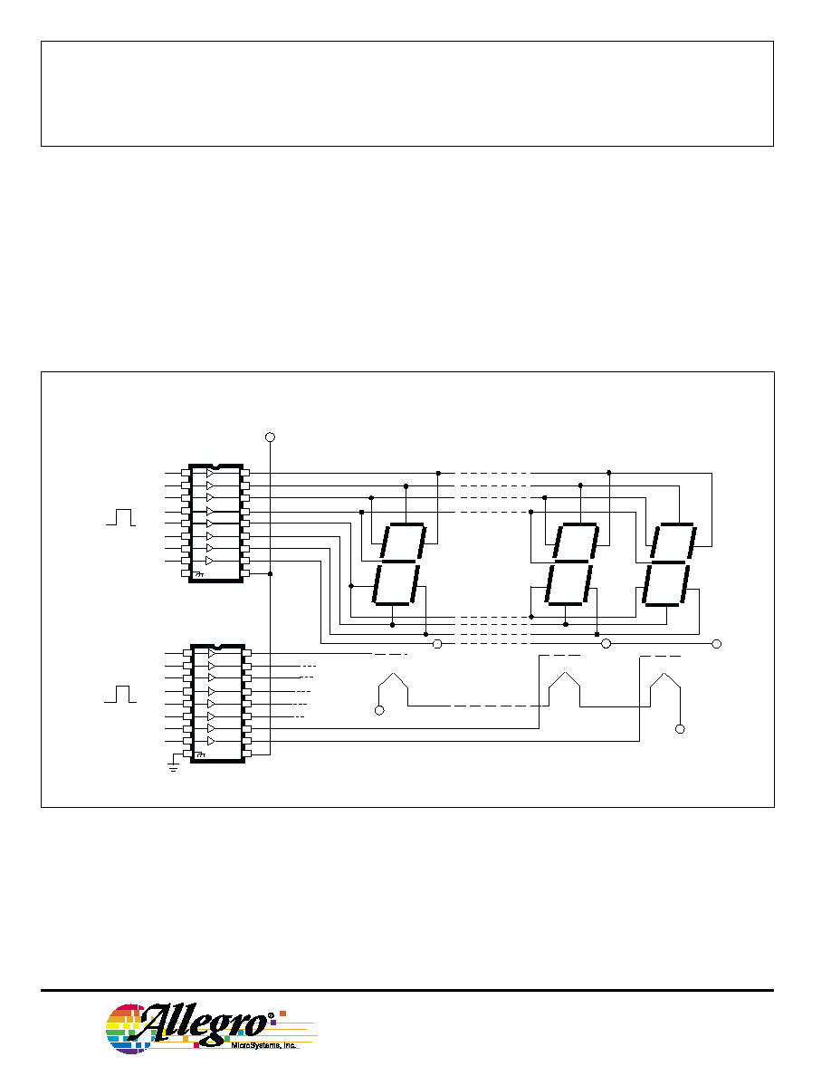
Dwg. No. A-10,261B
TYPICAL MULTIPLEXED FLUORESCENT DISPLAY
1
2
3
4
5
6
7
8
11
12
13
14
15
16
17
18
V
BB
9
10
1
2
3
4
5
6
7
8
11
12
13
14
15
16
17
18
V
BB
9
10
SEGMENT SELECT
V
BB
b
a
f
g
e
d
c
dp
D1
D
D
D
D
D
D
D
2
3
4
5
6
7
8
V
BIAS
V
FIL
DIGIT SELECT
UDN6118

6118
VACUUM FLUORESCENT
DISPLAY DRIVER
www.allegromicro.com
0.355
0.204
7.62
BSC
Dwg. MA-001-18A mm
10.92
MAX
18
1
9
7.11
6.10
5.33
MAX
1.77
1.15
0.39
MIN
0.558
0.356
2.54
BSC
0.13
MIN
3.81
2.93
10
23.37
22.35
UDN6118A
Dimensions in Inches
(controlling dimensions)
Dimensions in Millimeters
(for reference only)
NOTES: 1. Exact body and lead configuration at vendor's option within limits shown.
2. Lead spacing tolerance is non-cumulative.
3. Lead thickness is measured at seating plane or below.
4. Supplied in standard sticks/tubes of 21 devices.
0.014
0.008
0.300
BSC
Dwg. MA-001-18A in
0.430
MAX
18
1
9
0.280
0.240
0.210
MAX
0.070
0.045
0.015
MIN
0.022
0.014
0.100
BSC
0.005
MIN
0.150
0.115
10
0.920
0.880