LAST
TIME
BUY
--
April 2, 2001 --
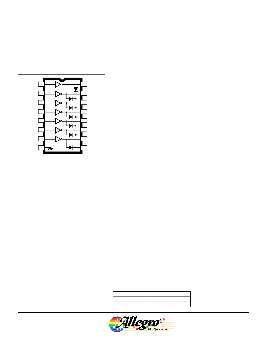
Integrating seven high-voltage, high-current npn Darlingtons into
a monolithic power array, the ULN7003A AND ULN7003LW are
designed for interfacing between TTL or CMOS logic and a variety of
peripheral loads. The seven open-collector Darlington outputs are
specified for 135 V minimum breakdown and 90 V minimum sustain-
ing. Included are integral power diodes for switching inductive loads.
Typical applications include relays, lamps, print heads and hammers,
solenoids, and level shifting to power discretes.
The ULN7003A/LW include input current-limiting resistors
compatible with the drive capabilities of TTL and (most) CMOS
operating at a nominal logic supply of 5 V. Operation with 12 V
CMOS may require additional input current limiting.
The high sustaining voltage rating of this power array makes it
ideal for inductive load applications where Zener diode flyback tech-
niques are used. The increased flyback voltage provides a much faster
inductive load turn-off current decay that is especially useful with
dc stepper motors, solenoids, and print heads.
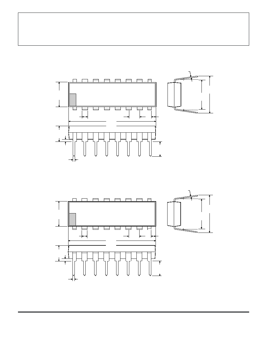
Both devices are pinned with outputs opposite inputs to facilitate
ease of circuit board layout. The ULN7003A is supplied in a 16-pin
plastic dual in-line package with a copper lead frame to maximize
device power dissipation capabilities. The ULN7003LW is furnished
in a 16-lead small-outline wide-body package for surface-mount
applications.
HIGH-VOLTAGE, HIGH-CURRENT
DARLINGTON ARRAY
16
15
14
13
12
6
11
7
10
8
9
1
2
3
4
5
ABSOLUTE MAXIMUM RATINGS
at T
A
= +25
�
C
Output Voltage, V
CEX
. . . . . . . . . . . . .
135 V
Output Sustaining Voltage,
V
CE(sus)
. . . . . . . . . . . . . . . . . . .
90 V
Output Current, I
C
. . . . . . . . . . . . . .
300 mA
Input Current, I
IN
. . . . . . . . . . . . . . . .
25 mA
Package Power Dissipation,
P
D
. . . . . . . . . . . . . . . . . .
See Graph
Operating Temperature Range,
T
A
. . . . . . . . . . . . . . .
-20
�
C to +85
�
C
Storage Temperature Range,
T
S
. . . . . . . . . . . . . .
- 55
�
C to +150
�
C
Output current may be limited by duty cycle,
number of drivers operating, ambient tem-
perature, and heat sinking. Under any set of
conditions, do not exceed the specified maximum
current rating or a junction temperature of 150
�C.
Dwg. No. A-9594
Part Number
Package
ULN7003A
16-Pin DIP
ULN7003LW
16-Lead SOIC
Always order by complete part number:
Note the ULN7003A (DIP) and the ULN7003LW
(SOIC) are electrically identical and share a
common terminal number assignment.
7003
Data Sheet
29304.10A
FEATURES
I
135 V Minimum Output Breakdown
I
90 V Minimum Sustaining Voltage
I
300 mA Output Current
I
Internal High-Current Clamp Diodes
I
Logic-Compatible Inputs

7003
HIGH-VOLTAGE,
HIGH-CURRENT
DARLINGTON ARRAY
115 Northeast Cutoff, Box 15036
Worcester, Massachusetts 01615-0036 (508) 853-5000
PARTIAL SCHEMATIC
(one of seven drivers)
Dwg. WP-001
OUTPUT
VOLTAGE
OUTPUT
CURRENT
ZENER CLAMP
DIODE CLAMP
V
CC
V
CE(SAT)
I
OUT
I
CEX
V + V
CC
F
V + V + V
CC
Z
F
A Zener diode can be used to increase the flyback
voltage. This gives a much faster inductive load turn-
OFF current decay. The maximum Zener voltage plus
the load supply voltage plus the internal diode forward
voltage must not exceed the device's rated sustaining
voltage.
COM
7.2K
3K
2.7K
Dwg. No. A-9651
93
50
50 pF
C
I
V
in
V
out
V
CC
Dwg. EP-020
PULSE
GENERATOR
PRR = 10 kHz
DC = 50%
SWITCHING DELAY TEST CIRCUIT
t pd
0
Dwg. WP-010
50%
50%
50%
50%
t pd
Vin
TURN ON
TURN OFF
V out
Dwg. No. WP-010
V
in
= 3.5 V for ULN7003A
Copyright � 1985, 2000 Allegro MicroSystems, Inc.
50
75
100
125
150
2.5
0.5
0
AMBIENT TEMPERATURE IN
�C
2.0
1.5
1.0
25
Dwg. GP-018B
SUFFIX 'A', R = 60
�C/W
JA
SUFFIX 'LW', R = 80
�C/W
JA
ALLOWABLE PACKAGE POWER DISSIPATION IN WATTS

7003
HIGH-VOLTAGE,
HIGH-CURRENT
DARLINGTON ARRAY
www.allegromicro.com
ELECTRICAL CHARACTERISTICS at T
A
= +25
�
C (unless otherwise noted).
Limits
Characteristic
Symbol
Test Conditions
Min.
Typ.
Max.
Units
Output Leakage Current
I
CEX
V
CE
= 135 V
--
--
50
�A
V
CE
= 135 V, T
A
= +70
�C
--
--
100
�A
Output Sustaining Voltage
V
CE(sus)
I
C
= 250 mA, L = 2 mH
90
--
--
V
Output Saturation Voltage
V
CE(SAT)
I
C
= 100 mA, I
IN
= 250
�A
--
1.1
1.3
V
I
C
= 250 mA, I
IN
= 350
�A
--
1.3
1.6
V
Input Current
I
IN(ON)
V
IN
= 3.85 V
--
0.93
1.35
mA
I
IN(OFF)
I
C
= 500
�A, T
A
= +70
�C
50
65
--
�A
Input Voltage
V
IN(ON)
V
CE
= 2.0 V, I
C
= 200 mA
--
--
2.4
V
V
CE
= 2.0 V, I
C
= 250 mA
--
--
2.7
V
Input Capacitance
C
IN
--
15
25
pF
Switching Delay
t
pd
Turn On, I
C
= 250 mA
--
0.05
1.0
�s
Turn Off, I
C
= 250 mA
--
0.5
1.0
�s
Clamp Diode Leakage Current
I
R
V
R
= 150 V
--
--
50
�A
V
R
= 150 V, T
A
= +70
�C
--
--
100
�A
Clamp Diode Forward Voltage
V
F
I
F
= 250 mA
--
1.7
2.0
V
Typical Data is for design information only.
TYPICAL INPUT CURRENT
AS A FUNCTION OF INPUT VOLTAGE
at T
A
= +25
�C
7003
HIGH-VOLTAGE,
HIGH-CURRENT
DARLINGTON ARRAY
115 Northeast Cutoff, Box 15036
Worcester, Massachusetts 01615-0036 (508) 853-5000
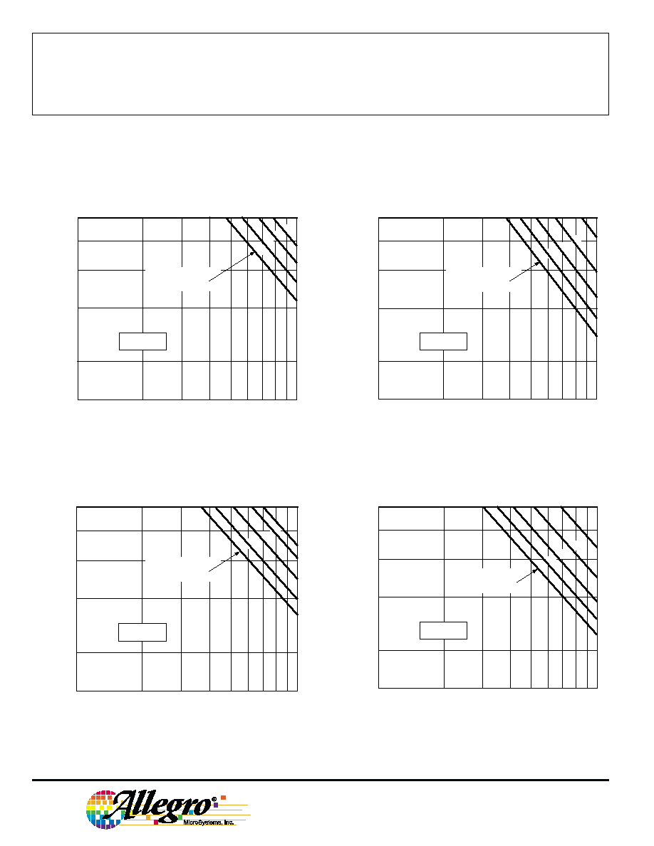
ALLOWABLE PEAK COLLECTOR CURRENT AS A
FUNCTION OF DUTY CYCLE
10
DUTY CYCLE IN PER CENT
300
Dwg. GP-015A
PEAK COLLECTOR CURRENT IN mA
50
30
75
150
100
70
100
250
200
20
T
A
= +50
�C
R
JA
= 60
�C/W
NUMBER OF OUTPUTS
CONDUCTING
SIMULTANEOUSLY
7
6
5
4
10
DUTY CYCLE IN PER CENT
300
Dwg. GP-015-1A
PEAK COLLECTOR CURRENT IN mA
50
30
75
150
100
70
100
250
200
20
T
A
= +70
�C
R
JA
= 60
�C/W
NUMBER OF OUTPUTS
CONDUCTING
SIMULTANEOUSLY
7
6
5
4
3
ULN7003LW at T
A
= +50
�C
ULN7003A at T
A
= +50
�C
ULN7003A at T
A
= +70
�C
ULN7003LW at T
A
= +70
�C
10
DUTY CYCLE IN PER CENT
300
Dwg. GP-015-3
PEAK COLLECTOR CURRENT IN mA
50
30
75
150
100
70
100
250
200
20
T
A
= +70
�C
R
JA
= 80
�C/W
NUMBER OF OUTPUTS
CONDUCTING
SIMULTANEOUSLY
7
6
5
4
3
10
DUTY CYCLE IN PER CENT
300
Dwg. GP-015-2
PEAK COLLECTOR CURRENT IN mA
50
30
75
150
100
70
100
250
200
20
T
A
= +50
�C
R
JA
= 80
�C/W
NUMBER OF OUTPUTS
CONDUCTING
SIMULTANEOUSLY
7
6
5
4
3