
Alpha Industries, Inc. [781] 935-5150
∑
Fax [617] 824-4579
∑
Email sales@alphaind.com
∑
www.alphaind.com
1
Specifications subject to change without notice. 5/00A
Features
s
1 Bit Attenuation of 32 dB DC≠1 GHz, 27 dB
1≠2 GHz, 24 dB 2≠2.5 dB
s
Combine with AA260-85 or AA101-80 for
63 dB 6 Bit Solution
s
Tune with One Capacitor and/or Resistor
to Desired Operating Frequency
and Attenuation
s
Ideal for Both IF and RF Applications Includ-
ing Cable, GSM, PCS, EDGE, 3G and ISM
SOT-6
AA104-73
Description
The AA104-73 is a 1 bit, GaAs IC FET digital attenuator in
a low cost SOT-6 package. This attenuator has up to
32 dB total attenuation.The attenuator requires two lines of
voltage control. The AA104-73 is particularly suited where
high attenuation accuracy, low insertion loss and low
Parameter
1
Frequency
2
Min.
Typ.
Max.
Unit
Insertion Loss
DC≠1.0 GHz
0.8
1.0
dB
1.0≠2.0 GHz
0.9
1.2
dB
2.0≠2.5 GHz
1.0
1.3
dB
Attenuation Range
DC≠1.0 GHz
32
dB
1.0≠2.0 GHz
27
dB
2.0≠2.5 GHz
24
dB
Attenuation Accuracy
3, 4
DC≠0.5 GHz
± (0.4 + 10% of Attenuation Setting in dB)
dB
0.85≠0.95 GHz
± (0.4 + 5% of Attenuation Setting in dB)
dB
1.7≠2.0 GHz
± (0.5 + 6% of Attenuation Setting in dB)
dB
2.0≠2.5 GHz
± (0.6 + 7% of Attenuation Setting in dB)
dB
VSWR (Insertion Loss State)
5
DC≠2.5 GHz
1.2:1
1.5:1
VSWR (Attenuation State)
5
DC≠2.5 GHz
1.5:1
2.0:1
Electrical Specifications at -40 to 85∞C (0, +3 V), (0, +5 V)
0.074
(1.90 mm REF.)
0.071 (1.80 mm)
0.052 (1.30 mm)
0.037 (0.95 mm) REF.
0.122 (3.10 mm)
0.106 (2.70 mm)
0.006
(0.15 mm)
0.000
(0.00 mm)
0.057 (1.45 mm)
0.035 (0.90 mm)
0.020 (0.51 mm)
0.014 (0.350 mm)
0.126 (3.20 mm)
0.087 (2.20 mm)
PIN 6
PIN 1
PIN 1
INDICATOR
0.022 (0.61 mm)
0.004 (0.10 mm)
0.014
(0.26 mm)
0.004
(0.10 mm)
0.012
(0.30 mm)
TYP.
5.0∞ ± 1∞
5.0∞ ± 1∞
Parameter
Condition
Frequency
Min.
Typ.
Max.
Unit
Switching Characteristics
6
Rise, Fall (10/90% or 90/10% RF)
50
ns
On, Off (50% CTL to 90/10% RF)
100
ns
Video Feedthru
25
mV
Input Power for 1 dB Compression
V
S
= +3 V
0.5≠2.5 GHz
14
+21
dBm
V
S
= +5 V
0.5≠2.5 GHz
18
+23
dBm
Intermodulation Intercept Point (IP3)
For Two-tone Input Power +10 dBm
V
S
= +3 V
0.5≠2.5 GHz
36
+41
dBm
V
S
= +5 V
0.5≠2.5 GHz
38
+44
dBm
Control Voltages
V
Low
= 0 to 0.2 V @ 20 µA Max.
V
High
= +3 V @ 100 µA Max. to +5 V @ 200 µA Max.
1. All measurements made in a 50
system, unless otherwise specified.
2. Operates to DC when controlled with negative voltage, C
BP
not required.
3. Attenuation value set by C
BP
.
4. Attenuation referenced to insertion loss.
5. Input/output. In band.
6. Video feedthru measured with 1 ns risetime pulse and 500 MHz bandwidth.
7. DC = 30 KHz.
GaAs IC 1 Bit Digital Attenuator
32 dB 2.5 GHz
intermodulation products are required. Typical application
is as a sixth bit value for the AA260-85 and AA101-80. A total
attenuation of 63 dB in 1 dB steps can be obtained by
combining the two attenuators.

GaAs IC 1 Bit Digital Attenuator 32 dB 2.5 GHz
AA104-73
2
Alpha Industries, Inc. [781] 935-5150
∑
Fax [617] 824-4579
∑
Email sales@alphaind.com
∑
www.alphaind.com
Specifications subject to change without notice. 5/00A
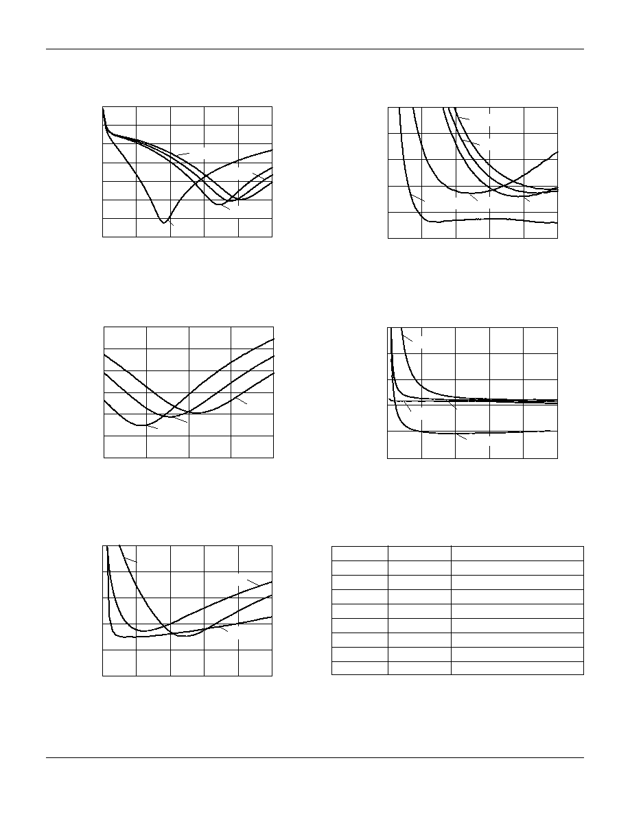
Typical Performance Data at -40 to 85∞C (0, +5 V) C
BP
= 12 pF, C
BL
= 47 pF
-1.50
-0.25
-0.50
-0.75
-1.00
-1.25
0
0.0
0.5
1.0
1.5
2.0
2.5
3.0
Insertion Loss (dB)
Frequency (GHz)
Insertion Loss vs. Frequency
IL 85∞C
IL -40∞C
IL 25∞C
-33
-27
-28
-29
-30
-31
-32
0.80 0.85 0.90 0.95 1.00 1.05 1.10 1.15 1.20
Max Attenuation (dB)
Frequency (GHz)
32 dB State vs. Frequency
32 dB -40∞C
32 dB 85∞C
32 dB 25∞C
1.0
1.2
1.4
1.6
1.8
2.0
0
0.5
1.0
1.5
2.0
2.5
3.0
VSWR
Frequency (GHz)
VSWR vs. Frequency
Insertion Loss State
S
11
25∞C
S
22
25∞C
S
22
85∞C
S
11
-40∞C
S
22
-40∞C
S
11
85∞C
1.0
3.0
2.5
2.0
1.5
0
0.5
1.0
1.5
2.0
2.5
3.0
VSWR
Frequency (GHz)
VSWR vs. Frequency
32 dB State
S
22
25∞C
S
11
25∞C
S
22
85∞C
S
11
-40∞C
S
22
-40∞C
S
11
85∞C
Control Voltage
Temperature
IP3 @ +10 dBm
(V)
(∞C)
each tone (dBm)
3
-40
41
3
25
42
3
85
40
5
-40
43
5
25
44
5
85
42
IP3 vs. Voltage and Temperature
1 dB
1 dB
Compression
Compression
Control Voltage
Temperature
Insertion Loss
32 dB State
(V)
(∞C) State
(dBm)
(dBm)
3
-40
21
16.5
3
25
21
15.0
3
85
21
14.0
5
-40
22
22.5
5
25
22
22.5
5
85
22
22.5
Compression Point vs.
Voltage and Temperature
Frequency: 500 MHz.
Two tone input power: +10 dBm each tone.
Tone frequencies: 500 and 501 MHz.
GaAs IC 1 Bit Digital Attenuator 32 dB 2.5 GHz
AA104-73
Alpha Industries, Inc. [781] 935-5150
∑
Fax [617] 824-4579
∑
Email sales@alphaind.com
∑
www.alphaind.com
3
Specifications subject to change without notice. 5/00A
Attenuation vs. Frequency DC≠2.5 GHz
C
BP
= 2.2, 2.7, 3.3 and 12 pF
Frequency (GHz)
Attenuation (dB)
-35
-30
-25
-20
-15
-10
-5
0
0
0.5
1.0
1.5
2.0
2.5
12 pF
2.2 pF
2.7 pF
3.3 pF
VSWR vs. Frequency DC≠2.5 GHz
C
BP
= 2.2, 2.7, 3.3 and 12 pF
0
0.5
1.0
1.5
2.0
2.5
Frequency (GHz)
VSWR
1.0
1.2
1.4
1.6
1.8
2.0
Ins. Loss
12 pF
2.2 pF
2.7 pF
3.3 pF
Attenuation vs. Frequency 1.5≠2.5 GHz
C
BP
= 2.2, 2.7, and 3.3 pF
Frequency (GHz)
Attenuation (dB)
-30.0
-27.5
-25.0
-22.5
-20.0
-17.5
-15.0
1.50
1.75
2.00
2.25
2.50
2.2 pF
2.7 pF
3.3 pF
Attenuation vs. Frequency DC≠0.5 GHz
C
BP
= 220, 1000, 1500 pF
Frequency (GHz)
Attenuation (dB)
-40
-36
-32
-28
-24
-20
0
0.1
0.2
0.3
0.4
0.5
1000 pF
1500 pF
220 pF
VSWR vs. Frequency DC≠0.5 GHz
C
BP
= 220, 1000, 1500 pF
Frequency (GHz)
VSWR
1.0
1.2
1.4
1.6
1.8
2.0
0 0.1
0.2
0.3
0.4
0.5
Ins. Loss
1000 pF
1500 pF
220 pF
C
BL
(pF)
C
BP
(pF)
Operating Frequency (GHz)
47
2.2
2.00≠2.30
47
2.7
1.80≠2.00
47
3.3
1.60≠1.80
47
12
0.90≠1.05
47
15
0.80≠0.90
330
220
0.20≠0.35
1500
1000
0.07≠0.20
10000
1500
0.015≠0.25
GaAs IC 1 Bit Digital Attenuator 32 dB 2.5 GHz
AA104-73
4
Alpha Industries, Inc. [781] 935-5150
∑
Fax [617] 824-4579
∑
Email sales@alphaind.com
∑
www.alphaind.com
Specifications subject to change without notice. 5/00A
-25
-15
-16
-17
-18
-19
-20
-21
-22
-23
-24
0
0.2
0.4
0.6
0.8
1.0
Max Attenuation (dB)
Frequency (GHz)
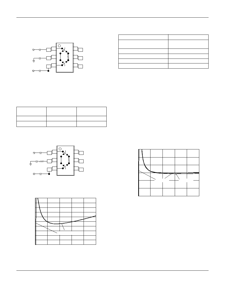
20 dB State vs. Frequency
C
BP
= 100 pF, C
BL
= 220 pF, R
BP
= 15
20 dB 25∞C
1.00
2.50
2.25
2.00
1.75
1.50
1.25
0
1.0
0.8
0.6
0.4
0.2
VSWR
Frequency (GHz)
VSWR vs. Frequency
20 dB State
S
22
25∞C
S
11
25∞C
Characteristic
Value
RF Input Power
1 W > 500 MHz 0/8 V
0.5 W @ 50 MHz 0/8 V
Supply Voltage
+8 V
Control Voltage
-0.2 V, +8 V
Operating Temperature
-40∞C to +85∞C
Storage Temperature
-65∞C to +150∞C
Absolute Maximum Ratings
Note: Exceeding these parameters may cause irreversible damage.
V
High
= +3 to +5 V.
C
BL
V
2
NC/GND
V
1
J
1
J
2
RF
GND
C
BL
C
BP
12
3
65
4
32
Pin Out
Attenuation
V
1
V
2
J
1
≠J
2
V
High
0
Reference I.L.
0
V
High
32 dB
Truth Table
Positive Control
Positive Voltage
C
BL
= 47 pF for frequencies >500 MHz. See Table on previous page for
C
BP
value.
See application notes APN2013 and APN2014 for 6 bit attenuator requirements.
C
BL
V
2
NC/GND
V
1
J
1
J
2
RF
GND
C
BL
R
BP
C
BP
12
3
65
4
20
Application: AA104-73 used as 1 Bit 20 dB Attenuator 25∞C (0, +5 V)
C
BL
= 220 pF, C
BP
= 100 pF, R
BP
= 15
, f
C
= 400 MHz with select values of
C
BP
and R
BP
, center frequency and attenuation value respectively
can be varied.