Alpha Industries, Inc. [781] 935-5150
∑
Fax [617] 824-4579
∑
Email sales@alphaind.com
∑
www.alphaind.com
1
Specifications subject to change without notice. 6/99A
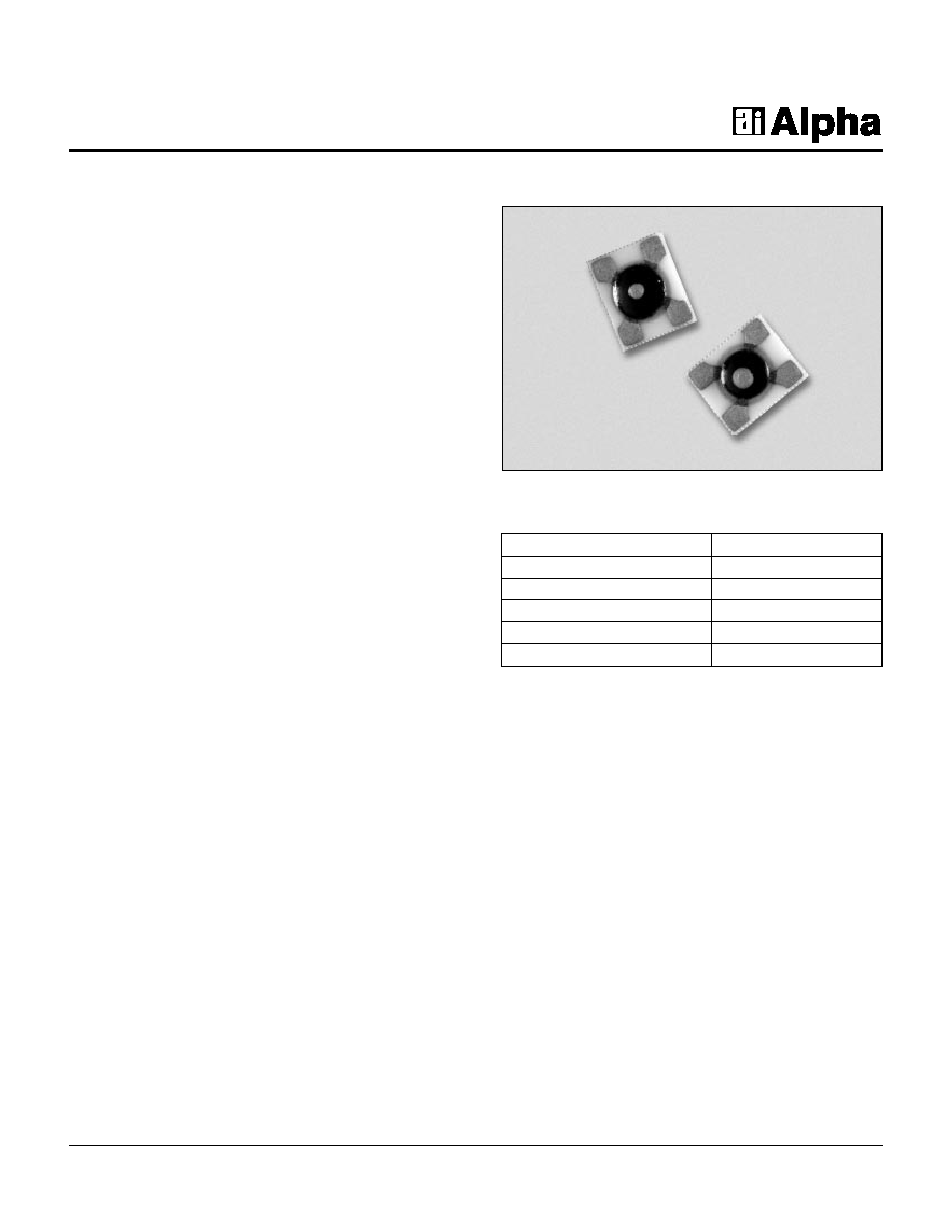
Chip On Board Mixer Quads
Features
s
High Volume Automatic Assembly
s
For Microwave MIC Assembly and
Automated High Volume Manufacturing
s
Mechanically Rugged Design
s
100% DC Tested
s
Three Barrier Heights for Customized
Mixer Performance
Description
Alpha's ceramic Chip on Board (COB) mixer quads are
designed for high performance RF and microwave receiver
applications. These devices utilize Alpha's advanced
silicon beamless Schottky technology, combined with
precision ceramic COB assembly techniques, to achieve
a high degree of device reliability in commercial
applications. Performance to 10 GHz is available with the
ring quads in the 106 package, which employs via hole
technology resulting in metalized contacts on the bottom
side and eliminating the need for wire bonds to topside
contacts.
Characteristic
Value
Maximum Current (I
MAX
)
50 mA
Power Dissipation (P
D
) CW
75 mW/Junction
Storage Temperature (T
ST
)
-65∞C to +175∞C
Operating Temperature (T
OP
)
-65∞C to +150∞C
ESD Human Body Model
Class 1B
Absolute Maximum Ratings

Part Number
Barrier
V
F
@ 1 mA
(
) V
F
@ 1 mA
1
C
J
@ 0 V
(
) C
T
@ 0 V
2
R
T
@ 10 mA
Outline
(mV)
(mV)
(pF)
(pF)
(
)
Drawing
Min.
Max.
Max.
Min.
Max.
Max.
Max.
Ring Quad (to 6 GHz)
DMF3926-101
Low
200
260
15
0.3
0.5
0.07
8
101
DME3927-101
Medium
300
400
15
0.3
0.5
0.07
8
101
DMJ3928-101
High
525
625
15
0.3
0.5
0.07
8
101
Ring Quad (to 10 GHz)
DMF3948-106
Low
250
310
15
0.05
0.15
0.07
15
106
DME3949-106
Medium
350
450
15
0.05
0.15
0.07
15
106
DMJ3950-106
High
575
675
15
0.05
0.15
0.07
15
106
Crossover Ring Quad (to 6 GHz)
DMF3926-100
Low
200
260
15
0.3
0.5
0.07
8
100
DME3927-100
Medium
300
400
15
0.3
0.5
0.07
8
100
DMJ3928-100
High
525
625
15
0.3
0.5
0.07
8
100
Back-to-Back Crossover Quad (to 6 GHz)
DMF3945-103
Low
200
260
15
0.3
0.5
0.07
8
103
DME3946-103
Medium
300
400
15
0.3
0.5
0.07
8
103
DMJ3947-103
High
525
625
15
0.3
0.5
0.07
8
103
Part Number
Barrier
V
F
@ 1 mA
(
) V
F
@
C
J
@ 0 V
(
) C
T
@ 0 V
2
R
T
@ 10 mA
V
B
@ 10
µ
µ
A
Outline
(mV)
1 mA
1
(mV)
(pF)
(pF)
(
)
(V)
Drawing
Min.
Max.
Max.
Min.
Max.
Max.
Max.
Min.
Bridge Quad (to 6 GHz)
DMF3929-102
Low
200
260
15
0.3
0.5
0.07
8
2
102
DME3930-102
Medium
300
400
15
0.3
0.5
0.07
8
3
102
DMJ3931-102
High
525
625
15
0.3
0.5
0.07
8
4
102
Chip On Board Mixer Quads
2
Alpha Industries, Inc. [781] 935-5150
∑
Fax [617] 824-4579
∑
Email sales@alphaind.com
∑
www.alphaind.com
Specifications subject to change without notice. 6/99A
Electrical Specifications at 25∞C
SPICE Model Parameters (Per Junction)
Parameter
Unit
DMF3926
DME3927
DMJ3928
DMF3948
DME3949
DMJ3950
DMF3929
DME3930
DMJ3931
DMF3945
DME3946
DMJ3947
IS
A
2.5E≠07
1.3E≠09
9.0E≠13
4.4E≠08
9.3E≠10
3.3E≠13
R
S
4
4
4
9
9
9
N
1.04
1.04
1.04
1.04
1.04
1.04
TT
s
1E≠11
1E≠11
1E≠11
1E≠11
1E≠11
1E≠11
C
J0
pF
0.42
0.39
0.39
0.11
0.10
0.10
M
0.32
0.37
0.42
0.32
0.37
0.42
E
G
eV
0.69
0.69
0.69
0.69
0.69
0.69
XTI
2
2
2
2
2
2
F
C
0.5
0.5
0.5
0.5
0.5
0.5
B
V
V
2
3
4
3
4
5
I
BV
A
1.0E≠05
1.0E≠05
1.0E≠05
1.0E≠05
1.0E≠05
1.0E≠05
V
J
V
0.495
0.595
0.800
0.495
0.595
0.800
1. Forward voltage difference between package electrodes.
2. Capacitance difference between package electrodes.

Chip On Board Mixer Quads
Alpha Industries, Inc. [781] 935-5150
∑
Fax [617] 824-4579
∑
Email sales@alphaind.com
∑
www.alphaind.com
3
Specifications subject to change without notice. 6/99A
100, 101, 102
106
103
GLASS NOT
SHOWN FOR CLARITY
INK DOT 0.010 (0.25 mm) DIA. MIN.
COLOR PER INTERNAL SPECIFICATION
0.026
(0.66 mm) MIN.
0.005 (0.13 mm)
0.001 (0.02 mm) TYP.
()
GLASS DAM
0.100 (2.54 mm)
+0.002 (0.05 mm)
-0.004 (0.10 mm)
EPOXY ENCAPSULATION
(BLACK)
0.040
(1.02 mm)
MAX.
0.020 (0.51 mm)
± 0.002 (0.05 mm)
0.020 (0.51 mm)
X 0.010 (0.25 mm)
ORIENTATION MARK
0.120 (3.05 mm)
+0.002 (0.05 mm)
-0.004 (0.10 mm)
0.030 (0.76 mm)
±0.003 (0.08 mm)
SQ.
EPOXY
ENCAPSULATION
EPOXY
ENCAPSULATION
0.024
(0.61 mm)
0.026
(0.66 mm)
0.017
(0.43 mm)
0.003
(0.08 mm) TYP.
0.003
(0.08 mm)
TYP
45∞ REF.
0.085 (2.159 mm) SQ.
0.020 (0.51 mm) MAX.
0.015
(0.38 mm)
GLASS
GOLD METALIZATION
Pd/Pt /Ag METALIZATION
Notes:
1. Bottom side is free of metalization.
2. The minimum specified area of the contact pads (0.017 x 0.022) shall
be free of epoxy.
CERAMIC SUBSTRATE
0.050
(1.27 mm)
MAX.
0.020 (0.51 mm)
±0.002 (0.05 mm)
0.130 (3.30 mm)
±0.003 (0.08 mm)
0.140 (3.56 mm)
± 0.003 (0.08 mm)
0.025 (0.64 mm)
±0.003 (0.08 mm)
0.020
(0.51 mm)
±0.003
(0.08 mm)
ORIENTATION
DOT
1
6
5
2
3
4
SCHEMATIC
DOT