Alpha Industries, Inc. [781] 935-5150
∑
Fax [617] 824-4579
∑
Email sales@alphaind.com
∑
www.alphaind.com
1
Specifications subject to change without notice. 1/01A
Low Distortion Attenuator
Plastic Packaged PIN Diodes
Features
s
Low Distortion Design
s
Frequency Range from HF to > 2 GHz
s
Designed for Base Station Applications
s
Configured for PI and TEE Attenuators
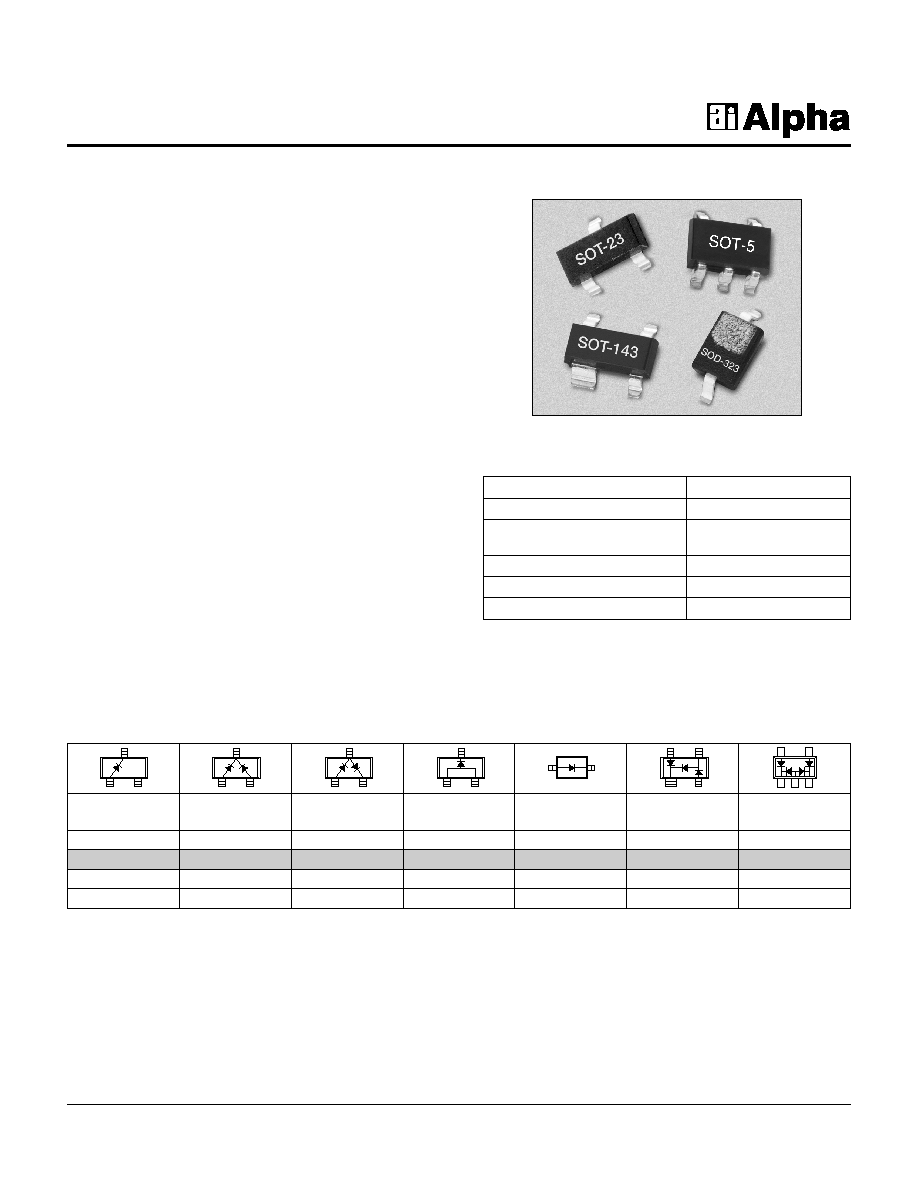
Description
The SMP1304 series of plastic packaged, surface
mountable, low capacitance (0.3 pF) silicon PIN diodes
are designed for use in attenuator applications from 5 MHz
to beyond 2 GHz. The thick 100
µ
m I region of these PIN
diodes makes them very attractive for use in low distortion
PI and TEE attenuators commonly used in TV distribution
applications. The 1
µ
S typical carrier lifetime of these
diodes results in resistance of 20
maximum at 1 mA and
7
maximum at 10 mA. Available in a selection of plastic
packages: as a single diode in the small footprint
SOD-323 package and in a variety of configurations in the
SOT-23 package, including a low inductance (0.4 nH)
SMP1304-007 package. Also available in the SOT-143
package are three diode junctions designed for insertion
in TEE attenuators (SMP1304-018) and PI attenuators
(SMP1304-019). Also available in a SOT-5 (SMP1304-027)
package as a four diode array designed for insertion in the
commonly used 4 diode PI attenuator circuit.
SMP1304 Series
Characteristic
Value
Reverse Voltage (V
R
)
200 V
Power Dissipation @ 25∞C Lead
250 mW
Temperature (P
D
)
Storage Temperature (T
ST
)
-65∞C to +150∞C
Operating Temperature (T
OP
)
-65∞C to +150∞C
ESD Human Body Model
Class 1C
Absolute Maximum Ratings
o
Available through distribution.
Single
Common Series
Pair
Low
Single
PI
PI
Cathode
Inductance
Marking: PG1
Marking: PG3
Marking: PG2
Marking: PGB
Marking: PGJ
Marking: PGM
SOT-23
SOT-23
SOT-23
SOT-23
SOD-323
SOT-143
SOT-5
o
SMP1304-001
o
SMP1304-004
o
SMP1304-005
o
SMP1304-007
o
SMP1304-011
o
SMP1304-019
o
SMP1304-027
L
S
= 1.5 nH
L
S
= 1.5 nH
L
S
= 1.5 nH
L
S
= 0.4 nH
L
S
= 1.5 nH
o
Available through distribution.
2
Alpha Industries, Inc. [781] 935-5150
∑
Fax [617] 824-4579
∑
Email sales@alphaind.com
∑
www.alphaind.com
Specifications subject to change without notice. 1/01A
Low Distortion Attenuator Plastic Packaged PIN Diodes
SMP1304 Series
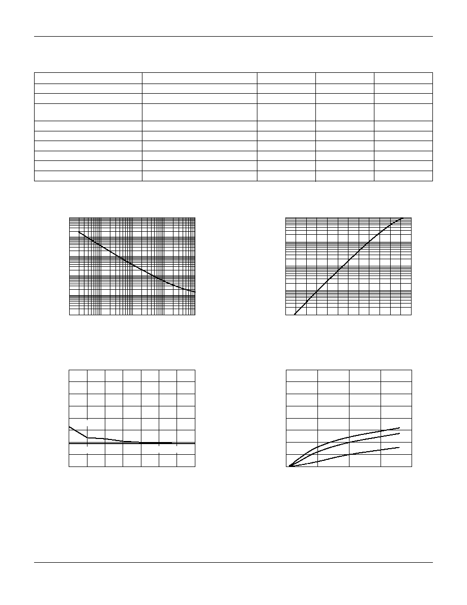
Series Resistance vs. Current @ 100 MHz
0.01
0.1
1
10
100
Forward Current (mA)
Series Resistance (
)
0.1
1
10
100
1000
10000
0
1
2
5
10
20
100
50
Capacitance vs. Reverse Voltage
0
0.2
0.4
0.6
0.1
0.3
0.5
0.7
0.8
Reverse Voltage (V)
Capacitance (pF)
100 MHz
1 MHz
1 GHz
400
500
600
700
800
900
1000
DC Characteristic
0.01
0.1
1
10
100
Forward Voltage (mV)
Forward Current (mA)
.
0
500
1000
1500
2000
Conductance vs. Frequency
and Reverse Voltage
Frequency (MHz)
Conductance (
µ
S)
0
50
100
150
200
250
300
350
400
0 V
10 V
40 V
Typical Performance Data
Parameter
Condition
Typ.
Max.
Unit
Reverse Current (I
R
)
V
R
= 200 V
10
µ
A
Capacitance (C
T
)
F = 1 MHz, V = 30 V
0.30
pF
Capacitance (C
T
)
F = 1 MHz, V = 30 V
0.45
pF
(SMP1304-018 & SMP1304-019)
Resistance (R
S
)
F = 100 MHz, I = 1 mA
40
50
Resistance (R
S
)
F = 100 MHz, I = 10 mA
7.0
Resistance (R
S
)
F = 100 MHz, I = 100 mA
2.0
Forward Voltage (V
F
)
IF = 10 mA
0.8
V
Carrier Lifetime (TI)
IF = 10 mA
1.0
µ
S
I Region Width
100
µ
m
Electrical Specifications at 25∞C
Low Distortion Attenuator Plastic Packaged PIN Diodes
SMP1304 Series
Alpha Industries, Inc. [781] 935-5150
∑
Fax [617] 824-4579
∑
Email sales@alphaind.com
∑
www.alphaind.com
3
Specifications subject to change without notice. 1/01A
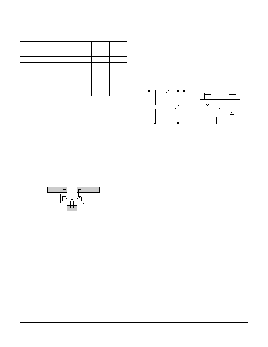
4
3
1
2
4
3
1
2
SMP1304-019 (PI)
SMP1304-007
In the -007 configuration of the SOT-23 package, the
package inductance is effectively reduced to 0.4 nH, in
comparison to the 1.5 nH value of the standard
configuration. This lower inductance will be particularly
beneficial when the diodes are used as shunt connected
switches at frequencies higher than 500 MHz, where
inductance is the primary limitation on maximum switch
isolation.
To achieve the effective 0.4 nH, the SOT-23 package must
be inserted in the microstrip circuit board with a gap in the
trace, as shown in the figure. Because of the polarity of
the diode junction, this low inductance feature is only
realizable with the cathode connected to ground.
SMP1304-019 PI Attenuator PIN Diodes
The SMP1304-019 employ three PIN diode junctions in
a SOT-143 package. They are configured for ease of
insertion in PI attenuator circuits commonly used from 10
MHz to beyond 1 GHz. The SMP1304 PIN diode junction
was designed for low capacitance, wide resistance
dynamic range and low distortion performance.
R
R
R
R
R
I
F
-55∞C
-15∞C
+25∞C
+65∞C
+100∞C
(mA)
(
)
(
)
(
)
(
)
(
)
0.02
1590.0
1660.0
1752.0
1770.0
1760.0
0.10
315.0
340.0
367.0
396.0
409.0
0.30
108.0
118.0
128.0
141.0
147.0
1.00
34.5
37.9
41.6
46.3
48.8
10.00
4.8
5.3
5.8
6.6
7.0
20.00
3.0
3.3
3.6
4.1
4.3
100.00
1.3
1.4
1.5
1.7
1.8
Resistance vs. Temperature @ 100 MHz
Ground
Gap
4
Alpha Industries, Inc. [781] 935-5150
∑
Fax [617] 824-4579
∑
Email sales@alphaind.com
∑
www.alphaind.com
Specifications subject to change without notice. 1/01A
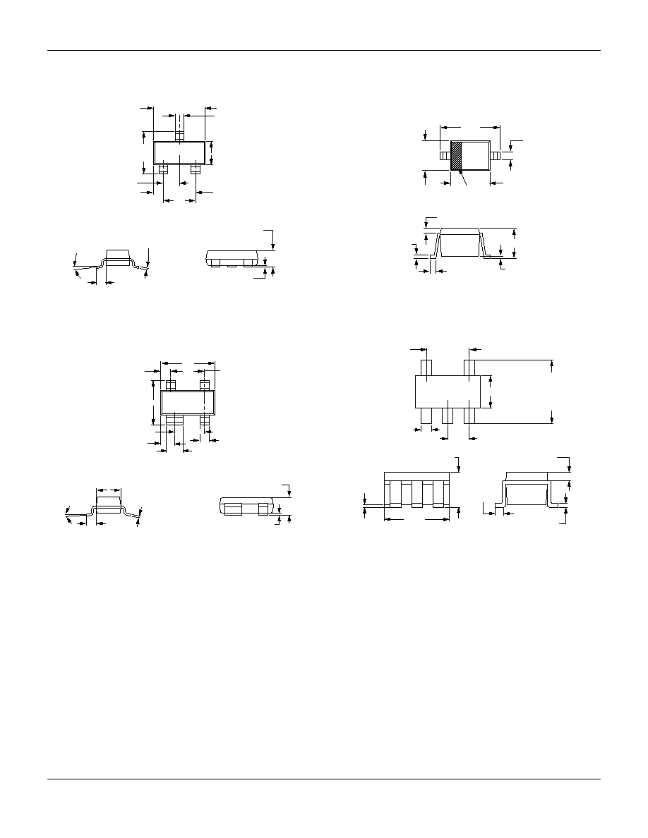
Low Distortion Attenuator Plastic Packaged PIN Diodes
SMP1304 Series
SOD-323
0.090 (2.30 mm) MIN.
0.108 (2.74 mm) MAX.
0.045 (1.15 mm) MIN.
0.053 (1.35 mm) MAX.
0.050
(1.25 mm) MAX.
0.006
(0.15 mm) TYP.
0.008 (0.20 mm) NOM.
0.004 (0.10 mm) MAX.
0.010 (0.25 mm) MIN.
0.010
(0.25 mm) MIN.
0.016
(0.40 mm) MAX.
0.063 (1.60 mm) MIN.
0.071 (1.80 mm) MAX.
CATHODE
INDICATOR
2
1
SOT-23
3
2
1
0.035 (0.89 mm) MIN.
0.044 (1.12 mm) MAX.
0.0005 (0.01 mm) MIN.
0.004 (0.10 mm) MAX.
0.012 (0.30 mm) MIN.
0.020 (0.50 mm) MAX.
0.003 (0.080 mm) MIN.
0.008 (0.20 mm) MAX.
8∞ MAX.
0.022 (0.55 mm) REF.
0.110 (2.80 mm) MIN.
0.120 (3.04 mm) MAX.
0.083 (2.10 mm) MIN.
0.104 (2.64 mm) MAX.
0.037 (0.95 mm) REF.
0.047 (1.20 mm) MIN.
0.055 (1.40 mm) MAX.
0.076 (1.92 mm) REF.
0.020 (0.51 mm) REF.
SOT-143
0.110 (2.80 mm) MIN.
0.120 (3.04 mm) MAX.
0.083 (2.10 mm) MIN.
0.104 (2.64 mm) MAX.
0.012 (0.30 mm) MIN.
0.020 (0.50 mm) MAX.
0.0005 (0.01 mm) MIN.
0.004 (0.15 mm) MAX.
0.031 (0.80 mm) MIN.
0.047 (1.20 mm) MAX.
0.030 (0.76 mm) MIN.
0.035 (0.89 mm) MAX.
0.047 (1.20 mm) MIN.
0.055 (1.40 mm) MAX.
0.003 (0.08 mm) MIN.
0.008 (0.20 mm) MAX.
0.022 (0.55 mm) REF.
8∞ MAX.
0.020 (0.50 mm) REF.
0.028 (0.70 mm) REF.
0.068 (1.72 mm) REF.
0.076 (1.92 mm) REF.
4
3
2
1
SOT-5
0.074
(1.90 mm)
REF.
0.118
(3.00 mm)
0.087
(2.20 mm)
0.012
(0.30 mm)
0.000
(0.00 mm)
MIN.
0.122 (3.10 mm)
0.106 (2.70 mm)
0.064 (1.63 mm)
0.035 (0.90 mm)
0.020 (0.51 mm)
0.014 (0.35 mm)
1
5
4
2
3
0.037 (0.95 mm) REF.
0.069
(1.75 mm)
0.052
(1.30 mm)
0.024
(0.61 mm)
0.004
(0.10 mm)
0.0104 (0.26 mm)
0.0035 (0.09 mm) MIN.
0.012 (0.30 mm) TYP.