
Advance information
Copyright ©2000 Alliance Semiconductor. All rights reserved.
Æ
AS4LC8M8S0
AS4LC4M16S0
7/5/00
ALLIANCE SEMICONDUCTOR
1
3.3V 4Mx16 and 8Mx8 CMOS synchronous DRAM
Features
∑ PC100/133 compliant
∑ Organization
- 2,097,152 words ◊ 8 bits ◊ 4 banks (8M◊8)
- 1,048,576 words ◊ 16 bits ◊ 4 banks (4M◊16)
∑ Fully synchronous
- All signals referenced to positive edge of clock
∑ Four internal banks controlled by BA0/BA1 (bank select)
∑ High speed
- 133/125/100 MHz
- 5.4 ns (133 MHz)/6 ns (125/100 MHz) clock access time
∑ Low power consumption
- Standby: 7.2 mW max, CMOS I/O
∑ 4096 refresh cycles, 64 ms refresh interval
∑ Auto refresh and self refresh
∑ Automatic and direct precharge
∑ Burst read, single write operation
∑ Can assert random column address in every cycle
∑ LVTTL compatible I/O
∑ 3.3V power supply
∑ JEDEC standard package, pinout and function
- 400 mil, 54-pin TSOP II
∑ Read/write data masking
∑ Programmable burst length (1/2/4/8/full page)
∑ Programmable burst sequence (sequential/interleaved)
∑ Programmable CAS latency (2/3)
Pin arrangement
A3
V
CC
A4
V
SS
V
CC
DQ0
V
CCQ
DQ1
DQ2
V
SSQ
DQ3
DQ4
V
CCQ
DQ5
DQ6
V
SSQ
DQ7
V
CC
LDQM
V
SS
DQ15
V
SSQ
DQ14
DQ13
V
CCQ
DQ12
DQ11
V
SSQ
DQ10
DQ9
V
CCQ
DQ8
V
SS
NC
UDQM
CLK
CKE
54
53
52
51
50
49
48
47
46
45
44
43
42
41
40
39
38
37
36
35
34
33
1
2
3
4
5
6
7
8
9
10
11
12
13
14
15
16
17
18
19
20
21
22
54-
p
i
n T
S
O
P
23
24
25
32
31
30
WE
CAS
RAS
CS
BA0
BA1
A10
A0
A1
A2
NC
A11
A9
A8
A7
A6
A5
26
27
29
28
NC
DQ1
NC
DQ2
NC
DQ3
NC
NC
DQ7
NC
DQ6
NC
DQ5
NC
DQ4
NC
DQM
4L
C
4
M1
6S
0
A3
V
CC
V
CC
DQ0
V
CCQ
V
SSQ
V
CCQ
V
SSQ
V
CC
WE
CAS
RAS
CS
BA0
BA1
A10
A0
A1
A2
A4
V
SS
V
SS
V
SSQ
V
CCQ
V
SSQ
V
CCQ
V
SS
NC
CLK
CKE
NC
A11
A9
A8
A7
A6
A5
AS4LC4M16S0
AS4LC4M16S0
Pin designation
Pin(s)
Description
DQM (8M◊8)
UDQM/LDQM (4M◊16)
Output disable/write mask
A0 to A11
Address inputs
BA0, BA1
Bank select inputs
DQ0 to DQ7 (8M◊8)
DQ0 to DQ15 (4M◊16)
Input/output
RAS
Row address strobe
CAS
Column address strobe
WE
Write enable
CS
Chip select
V
CC
, V
CCQ
Power (3.3V ± 0.3V)
V
SS
, V
SSQ
Ground
CLK
Clock input
CKE
Clock enable
Selection guide
Symbol
-75 (PC133)
-8
-10F (PC100)
-10 (PC100)
Unit
Bus frequency
f
max
133
125
100
100
MHz
Minimum clock access time
CL = 2
t
AC
≠
≠
6
≠
ns
CL = 3
t
AC
5.4
6
≠
6
ns
Minimum setup time
t
S
1.5
2
2
2
ns
Minimum hold time
t
H
0.8
1.0
1.0
1.0
ns
Minimum RAS to CAS delay
t
RCD
3
3
2
3
cycles
Minimum RAS precharge time
t
RP
3
3
2
3
cycles
Remarks: (CL/t
RCD
/t
RP
)
3/3/3
3/3/3
2/2/2
3/3/3

Æ
2
ALLIANCE SEMICONDUCTOR
7/5/00
AS4LC4M16S0
AS4LC16M4S0
Functional description
The AS4LC8M8S0 and AS4LC4M16S0 are high-performance 64-megabit CMOS Synchronous Dynamic Random Access
Memory (SDRAM) devices organized as 2,097,152 words ◊ 8 bits ◊ 4 banks, and 1,048,576 words ◊ 16 bits ◊ 4 banks,
respectively. Very high bandwidth is achieved using a pipelined architecture where all inputs and outputs are referenced to the
rising edge of a common clock. Programmable burst mode can be used to read up to a full page of data without selecting a
new column address.
The four internal banks can be alternately accessed (read or write) at the maximum clock frequency for seamless interleaving
operations. This provides a significant advantage over asynchronous EDO and fast page mode devices.
This SDRAM product also features a programmable mode register, allowing users to select read latency as well as burst length
and type (sequential or interleaved). Lower latency improves first data access in terms of CLK cycles, while higher latency
improves maximum frequency of operation. This feature enables flexible performance optimization for a variety of
applications.
DRAM commands and functions are decoded from control inputs. Basic commands are as follows:
The 64 Mb DRAM devices are available in 400-mil plastic TSOP II packages and have 54 pins in each configuration. Both
devices operate with a power supply of 3.3V ± 0.3V. Multiple power and ground pins are provided for low switching noise
and EMI. Inputs and outputs are LVTTL-compatible.
Logic block diagram
For AS4LC8M8S0, Banks A-D will read 8M◊8 (4096◊512◊8).
For AS4LC4M16S0, DQM will be UDQM and LDQM.
∑ Mode register set
∑ Deactivate bank
∑ Deactivate all banks
∑ Select row; activate bank
∑ Select column; write
∑ Select column; read
∑ Deselect; power down
∑ CBR refresh
∑ Auto precharge with read/write ∑ Self-refresh
RAS
CAS
WE
CLK
CKE
Clock generator
Mode register
Comma
n
d
decoder
Con
t
r
ol lo
g
i
c
Row
address
buffer
Refresh
counter
Column
address
buffer
Burst
counter
Ro
w
dec
ode
r
Column decoder and
latch circuit
Data control circuit
Lat
c
h
cir
c
u
i
t
I
n
p
u
t
a
n
d
ou
t
p
u
t
b
u
f
f
e
r
DQ
A[11:0]
DQM
CS
Bank select
BA0, BA1
Bank A
1M◊16
(4096◊256◊16)
Bank B
1M◊16
(4096◊256◊16)
Bank C
1M◊16
(4096◊256◊16)
Bank D
1M◊16
(4096◊256◊16)
Sense amplifier
Æ
AS4LC8M8S0
AS4LC4M16S0
7/5/00
ALLIANCE SEMICONDUCTOR
3
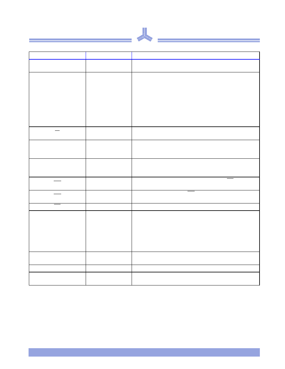
Pin descriptions
Pin
Name
Description
CLK
System clock
All operations synchronized to rising edge of CLK. It also increments
the burst counters.
CKE
Clock enable
Controls CLK input. If CKE is high, the next CLK rising edge is valid.
If CKE is low, the internal clock is suspended from the next clock
cycle and the burst address and output states are frozen. Pulling CKE
low has the following effects:
all banks idle: Precharge power down and Self refresh.
row active in any bank: Active power down.
burst/access in progress: Clock suspend.
When in Power down or Self refresh mode, CKE becomes
asynchronous until exiting the mode.
CS
Chip select
Enables or disables device operation by masking or enabling all inputs
except CLK, CKE, UDQM/LDQM (
◊
16), DQM (
◊
8).
A0~A11
Address
Row and column addresses are multiplexed. Row address: A0~A11.
Column address (8M
◊
8): A0~A8. Column address (4M
◊
16):
A0~A7.
BA0, BA1
Bank select
Memory cell array is organized in 4 banks. BA0 and BA1 select which
internal bank will be active during activate, read, write, and
precharge operations.
RAS
Row address strobe
Enables row access and precharge operation. When
RAS
is low, row
address is latched at the rising edge of CLK.
CAS
Column address strobe
Enables column access. When CAS is low, starting column address for
the burst access operation is latched at the rising edge of the CLK.
WE
Write enable
Enables write operation and row precharge operation.
◊
8: DQM
◊
16: UDQM/LDQM
Output disable/ write
mask
Controls I/O buffers. When DQM is high, output buffers are disabled
during a read operation and input data is masked during a write
operation. DQM latency is 2 clocks for Read and 0 clocks for Write.
For
◊
16, LDQM controls lower byte (DQ0≠7) and UDQM controls
upper byte (DQ8≠15). For
◊
8, only one DQM controls the 8 DQs.
UDQM and LDQM are considered same state when referenced as
DQM.
DQ0~DQ15
Data input/output
Data inputs/outputs are multiplexed. Data bus for 8M
◊
8 is
DQ0~DQ7 only.
V
DD
/V
SS
Power supply/ground Power and ground for core logic and input buffers.
V
DDQ
/V
SSQ
Data output power/
ground
Power and ground for data output buffers.

Æ
4
ALLIANCE SEMICONDUCTOR
7/5/00
AS4LC4M16S0
AS4LC16M4S0
Commands
1
OP = operation code.
A0~A11 and BA0~BA1 program keys.
2
MRS can be issued only when all banks are precharged. A new command can be issued 1 clock cycle after MRS.
3
Auto refresh functions similarly to CBR DRAM refresh. However, precharge is automatic.
Auto/self refresh can only be issued after all banks are precharged.
4
BA0~BA1: bank select addresses.
If A10/AP is High at row precharge, BA0 and BA1 are ignored and all banks are selected.
During read, write, row active, and prechage:
If BA0 and BA1 are Low, Bank A is selected.
If BA0 = Low and BA1 = High, Bank B is selected.
If BA0 = High and BA1 = Low, Bank C is selected.
If BA0 and BA1 are High, Bank D is selected.
5
A new read/write command to the same bank cannot be issued during a burst read/write with auto precharge.
A new row active command can be issued after t(t
RP
/t
CK
+ BL +) cycles.
6
Burst stop command valid at every burst length.
7
DQM sampled at positive edge of CLK. Data-in may be masked at every CLK (Write DQM latency is 0).
Data-out mask is active 2 CLK cycles after issuance. (Read DQM latency is 2).
Command
CKE
n-1
CKE
n
CS
RAS
CAS
WE
DQM
BA0/
BA1
A10
A9≠A0
DQ
Note
Register
Mode register set
H
*
H
L
L
L
L
X
Op code
X
1,2
Refresh
Auto refresh
H
H
L
L
L
H
X
≠
X
≠
X
3
Self
refresh
Entry
H
L
L
L
L
H
X
≠
≠
3
Exit
L
H
L
H
H
H
X
≠
≠
3
H
X
X
X
X
≠
≠
3
Bank activate
H
H
L
L
H
H
X
V
row address
X
Read
Auto precharge disable
H
H
L
H
L
H
X
V
L
column
address
X
4
Auto precharge enable
H
4,5
Write
Auto precharge disable
H
H
L
H
L
L
X
V
L
column
address
Valid
4
Auto precharge enable
H
4,5
Burst stop
H
H
L
H
H
L
X
X
Active
6
Precharge
Selected bank
H
H
L
L
H
L
X
V
L
X
X
4
All banks
X
H
Clock suspend or
active power down
Entry
H
L
H
X
X
X
X
X
X
X
X
L
V
V
V
Exit
L
H
X
X
X
X
Precharge power
down mode
Entry
H
L
H
X
X
X
X
X
X
X
X
L
H
H
H
Exit
L
H
H
X
X
X
L
V
V
V
DQM
Write enable/output
enable
H
H
X
X
X
X
H
X
X
X
X
7
Write inhibit/Output
High-Z
No operation command
H
X
H
X
X
X
X
X
X
X
X
L
H
H
H
X
Æ
AS4LC8M8S0
AS4LC4M16S0
7/5/00
ALLIANCE SEMICONDUCTOR
5
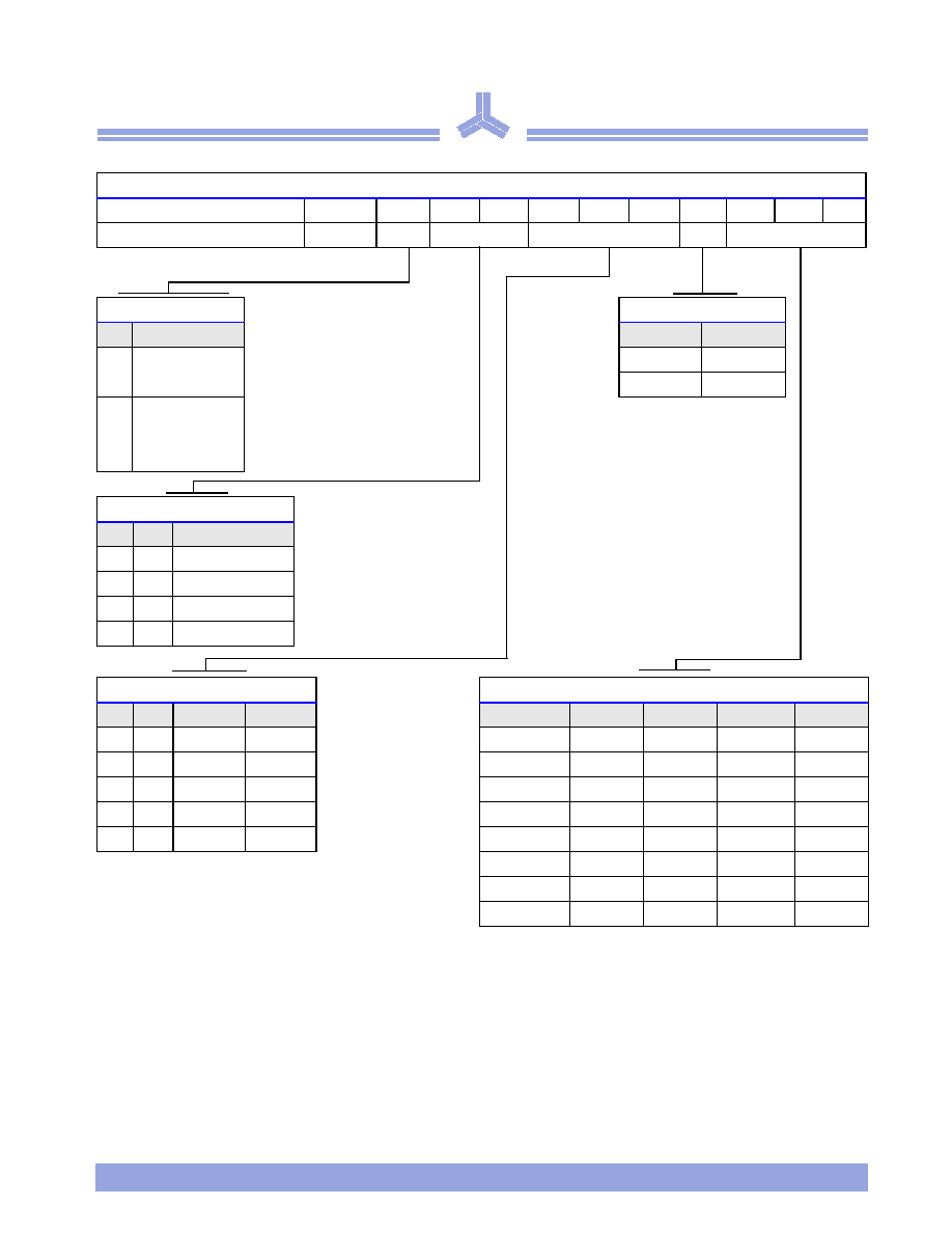
Mode register fields
RFU = 0 during MRS cycle.
Register programmed with MRS
Address
A11~A10
A9
A8
A7
A6
A5
A4
A3
A2
A1
A0
Function
RFU
WBL
TM
CAS latency
BT
Burst length
Write burst length
Burst type
A9
Length
A3
Type
0
Programmed
burst length
0
Sequential
1
Interleaved
1
Single burst
Test mode
A8
A7
Type
0
0
Mode register set
0
1
Reserved
1
0
Reserved
1
1
Reserved
CAS latency
Burst length
A6
A5
A4
Latency
A2
A1
A0
BT = 0
BT = 1
0
0
0
Reserved
0
0
0
1
1
0
0
1
Reserved
0
0
1
2
2
0
1
0
2
0
1
0
4
4
0
1
1
3
0
1
1
8
8
1
X
X
Reserved
1
0
0
Reserved
Reserved
1
0
1
Reserved
Reserved
1
1
0
Reserved
Reserved
1
1
1
Full page
Reserved