 | –≠–ª–µ–∫—Ç—Ä–æ–Ω–Ω—ã–π –∫–æ–º–ø–æ–Ω–µ–Ω—Ç: AME7107A | –°–∫–∞—á–∞—Ç—å:  PDF PDF  ZIP ZIP |

AME, Inc.
1
AME7106/AME7106A/AME7106R
AME7107/AME7107A/AME7107R
3-1/2 Digit A/D Converter
High Accuracy, Low Power
n
n
n
n
n
Key Features
l
100
µ
V Resolution
l
High Impedance Differential Inputs
l
Differential Reference
l
Drive LCD (AME7106) or LED (AME7107)
Directly
l
Four New Convenient Features
(AME7106A/AME7107A)
l
Display-Hold
l
Low-Battery Indication
l
Integration Status Indication
l
De-Integration Status Indication
n
n
n
n
n
Applications
l
Digital multimeter
l
pH meter
l
Capacitance meter
l
Thermometer
l
Digital Panel meter
l
Photometer
n
n
n
n
n
General Description
The AME7106 and AME7107 family are high perfor-
mance, low power, 3-1/2 digit, dual-slope integrating A/
D converters, with on-chip display drivers. The
AME7106 is designed for a single battery operated sys-
tem, will drive non-multiplexed LCD display directly.
The AME7107 is designed for a dual power supply sys-
tem, will directly drive common anode LED display.
These A/D converters are inherently versatile and ac-
curate. They are immune to the high noise environ-
ments. The true differential high impedance inputs and
differential reference are very useful for making
ratiometric measurement, such as resistance, strain
gauge and bridge transducers. The built-in auto-zero
feature automatically corrects the system offset with-
out any external adjustments.
Display-hold, low-battery flag, integration and de-inte-
gration status flags are four additional features which
are available in the 44-pin package, AME7106ACKW
and AME7107ACKW.
n
n
n
n
n
Typical Operating Circuit
* For the operating circuit of the reverse-pins version, please refer
to pin configuration on page 4 and pin description on page 5 & 6
AME, Inc.
2
AME7106/AME7106A/AME7106R
AME7107/AME7107A/AME7107R
3-1/2 Digit A/D Converter
High Accuracy, Low Power
n
n
n
n
n
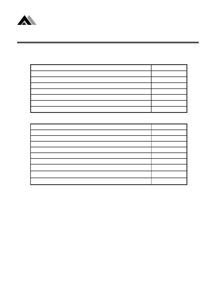
Absolute Maximum Ratings
AME7106
AME7107
Static sensitive device. Unused devices must be stored in the conductive material.
Protect device from static discharge and static field. Stresses exceed the above Absolute Maximum
Ratings may cause permanent damage to the device. Exposure to Absolute Maximum Rating Con-
ditions for extended periods may affect the reliability of the device.
Supply Voltage (V+ to V-)
12V
Analog Input Voltage (Either inputs)
V+ TO V-
Reference Input Voltage (Either inputs)
V+ TO V-
Clock Input
Test to V+
Power Dissipation
800mW
Operating Temperature
0
o
C to 70
o
C
Storage Temperature
-55
o
C to 150
o
C
Lead Temperature (Soldering 60 seconds)
300
o
C
Supply Voltage
V+
6V
V-
-6V
Analog Input Voltage (Either inputs)
V+ to V-
Reference Input Voltage (Either inputs)
V+ to V-
Clock Input
Gnd to V+
Power Dissipation
800mW
Operating Temperature
0
o
C to 70
o
C
Storage Temperature
-55
o
C to 150
o
C
Lead Temperature (Soldering 60 seconds)
300
o
C
AME, Inc.
3
AME7106/AME7106A/AME7106R
AME7107/AME7107A/AME7107R
3-1/2 Digit A/D Converter
High Accuracy, Low Power
n
n
n
n
n
Ordering Information
Part Number
Display
Marking
Package
Pin Layout
Temp. Range
AME7106CPL
LCD
AME7106CPL
YYWW
40 Pin PDIP
Normal
0
o
C to 70
o
C
AME7106RCPL
LCD
AME7106RCPL
YYWW
40 Pin PDIP
Reverse
0
o
C to 71
o
C
AME7106ACKW
LCD
AME7106ACKW
YYWW
44 Pin PQFP
Normal
0
o
C to 72
o
C
AME7106Y
LCD
AME7106Y
YYWW
44 Pin Dice
Normal
0
o
C to 73
o
C
AME7107CPL
LED
AME7107CPL
YYWW
40 Pin PDIP
Normal
0
o
C to 74
o
C
AME7107RCPL
LED
AME7107RCPL
YYWW
40 Pin PDIP
Reverse
0
o
C to 75
o
C
AME7107ACKW
LED
AME7107ACKW
YYWW
44 Pin PQFP
Normal
0
o
C to 76
o
C
AME7107Y
LED
AME7107Y
YYWW
44 Pin Dice
Normal
0
o
C to 77
o
C

AME, Inc.
4
AME7106/AME7106A/AME7106R
AME7107/AME7107A/AME7107R
3-1/2 Digit A/D Converter
High Accuracy, Low Power
n
n
n
n
n
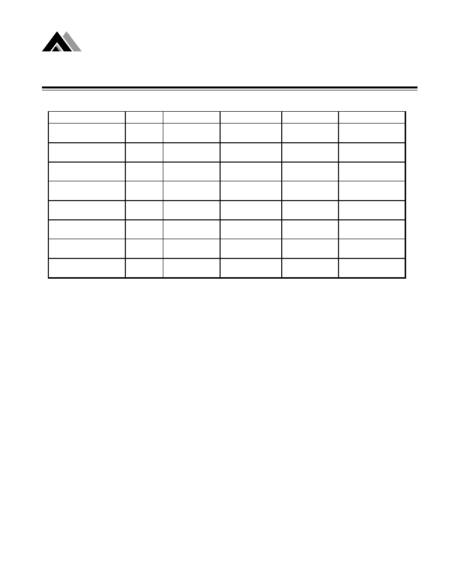
Electrical Characteristics
Unless otherwise noted, AME7106 & AME7107 are specified at T
A
= 25
O
C
, f
clock
= 48KHz. Supply voltage = 9V (V+ to V-)
Notes: 1. Input voltage may exceed the supply voltages provided the input current is limited to ±100
µ
A.
2. Dissipation rating assumes a device is mounted with all leads soldered to printed circuit board.
Parameter
Conditions
Min
Typ
Max
Unit
Vin = 0V
0
Digital Reading
Full-Scale = 200.0mV
Ratiometric Reading
Vin = Vref = 100.0mV
999
999/1000
1000
Digital Reading
Roll-Over Error
-1
≠0.2
+1
Counts
(Difference in Reading for
Equal Positive and Negative
Reading Near Full-Scale)
Linearity (Max. Deviation
Full-Scale = 200.0mV
-1
≠0.2
+1
Counts
From Best Straight Line Fit)
Common-Mode
Vcm = ≠1V, Vin =0V
50
µ
V/V
Rejection Ratio
Full-Scale = 200.0mV
Noise (Pk-Pk Value Not
Vin = 0V
15
µ
V
Exceeded 95% of Time)
Full-Scale = 200.0mV
Leakage Current at Input
Vin = 0V
1
10
pA
Zero Reading Drift
Vin = 0V, 0
O
C to 70
O
C
0.2
1
µ
V/
O
C
Supply Current
Vin = 0V
0.8
1.2
mA
(Excluding LED current
for 7107)
Analog Common Voltage
25K
Between
2.8
3.0
3.2
V
(With respect to V+)
Common and V+
Temp. Coeff. of Analog
25K
Between
50
75
ppm/
O
C
Common (With respect to V+)
Common and V+
0
O
C
TA
70
O
C
Low Battery Flag
V+ to V-
6.3
7.0
7.7
V
Test Pin Voltage
With respect to V+
4
5
6
V
(AME7106 only)
LCD Segment Drive Voltage
V+ to V- = 9V
4
5
6
V
(AME7106 only)
Backplane Drive Voltage
V+ to V- = 9V
4
5
6
V
(AME7106 only)
Segment Sinking Current
V+ = 5.0V
5
8.0
mA
(Except Segment AB4)
Segment Voltage = 3V
(AME7107 only)
Segment Sinking Current
V+ = 5.0V
10
16
mA
(Segment AB4)
Segment Voltage = 3V
(AME7107 only)
-Vin=+Vin
200.0mV
Zero Input Reading

AME, Inc.
5
AME7106/AME7106A/AME7106R
AME7107/AME7107A/AME7107R
3-1/2 Digit A/D Converter
High Accuracy, Low Power
n
Pin Configurations