 | –≠–ª–µ–∫—Ç—Ä–æ–Ω–Ω—ã–π –∫–æ–º–ø–æ–Ω–µ–Ω—Ç: FS6131-01 | –°–∫–∞—á–∞—Ç—å:  PDF PDF  ZIP ZIP |

I
2
C is a licensed trademark of Philips Electronics, N.V. Windows and Windows NT are registered trademarks of Microsoft Corporation. American Microsystems, Inc. reserves the right to change detail
specifications as may be required to permit improvements in the design of its products.
FS6131-01
FS6131-01
FS6131-01
FS6131-01
Programmable Line Lock Clock Generator IC
Programmable Line Lock Clock Generator IC
Programmable Line Lock Clock Generator IC
Programmable Line Lock Clock Generator IC
1.0 Features
∑
Complete programmable control via I
2
C
‰
-bus
∑
Selectable CMOS or PECL compatible outputs
∑
External feedback loop capability allows genlocking
∑
Tunable VCXO loop for jitter attenuation
∑
Commercial (FS6131-01) and industrial (FS6131-01i)
temperature versions available
2.0 Description
The FS6131-01 is a monolithic CMOS clock genera-
tor/regenerator IC designed to minimize cost and compo-
nent count in a variety of electronic systems. Via the I
2
C-
bus interface, the FS6131-01 can be adapted to many
clock generation requirements.
The ability to tune the on-board voltage-controlled crystal
oscillator (VCXO), the length of the Reference and Feed-
back Dividers, their granularity, and the flexibility of the
Post Divider make the FS6131-01 the most flexible
stand-alone phase-locked loop (PLL) clock generator
available.
3.0 Applications
∑
Frequency
Synthesis
∑
Line-Locked and Genlock Applications
∑
Clock
Multiplication
∑
Telecom
Jitter
Attenuation
Figure 1: Pin Configuration
1
16
2
3
4
5
6
7
8
15
14
13
12
11
10
9
SCL
SDA
ADDR
VSS
XIN
XOUT
XTUNE
VDD
LOCK/IPRG
EXTLF
VSS
REF
FBK
VDD
CLKP
CLKN
16-pin 0.150" SOIC
F
S
6
131
Figure 2: Block Diagram
FS6131
VCXO
Divider
(optional)
(optional)
CRYSTAL LOOP
MAIN LOOP
VCXO
XOUT
XIN
Control
ROM
XTUNE
Reference
Divider
(N
R
)
Phase-
Frequency
Detector
Charge
Pump
UP
DOWN
REF
FBK
Phase-
Frequency
Detector
Charge
Pump
UP
DOWN
Feedback
Divider
(N
F
)
Internal
Loop
Filter
EXTLF
I
2
C
Interface
SCL
SDA
ADDR
Registers
POST3[1:0]
POST2[1:0]
POST1[1:0]
REFDIV[11:0]
FBKDIV[13:0]
EXTLF
PDREF
PDFBK
VCOSPD,
OSCTYPE
LFTC
MLCP[1:0]
XLCP[1:0]
XLROM[2:0]
XLPDEN,
XLSWAP
REFDSRC
XCT[3:0],
XLVTEN
(f
REF
)
(f
VCO
)
LOCK/
IPRG
Post
Divider
(N
Px
)
Voltage
Controlled
Oscillator
Lock
Detect
CMOS
(optional)
STAT[1:0]
OUTMUX[1:0]
Clock
Gobbler
GBL
(optional)
FBKDSRC[1:0]
CMOS/PECL
Output
CLKN
(f
CLK
)
CLKP
R
LF
C
LF
C
LP
11
00
10
01
01
00
10
11
1
0
1
0
0
1
1
0
1
0

2
FS6131-01
FS6131-01
FS6131-01
FS6131-01
Programmable Line Lock Clock Generator IC
Programmable Line Lock Clock Generator IC
Programmable Line Lock Clock Generator IC
Programmable Line Lock Clock Generator IC
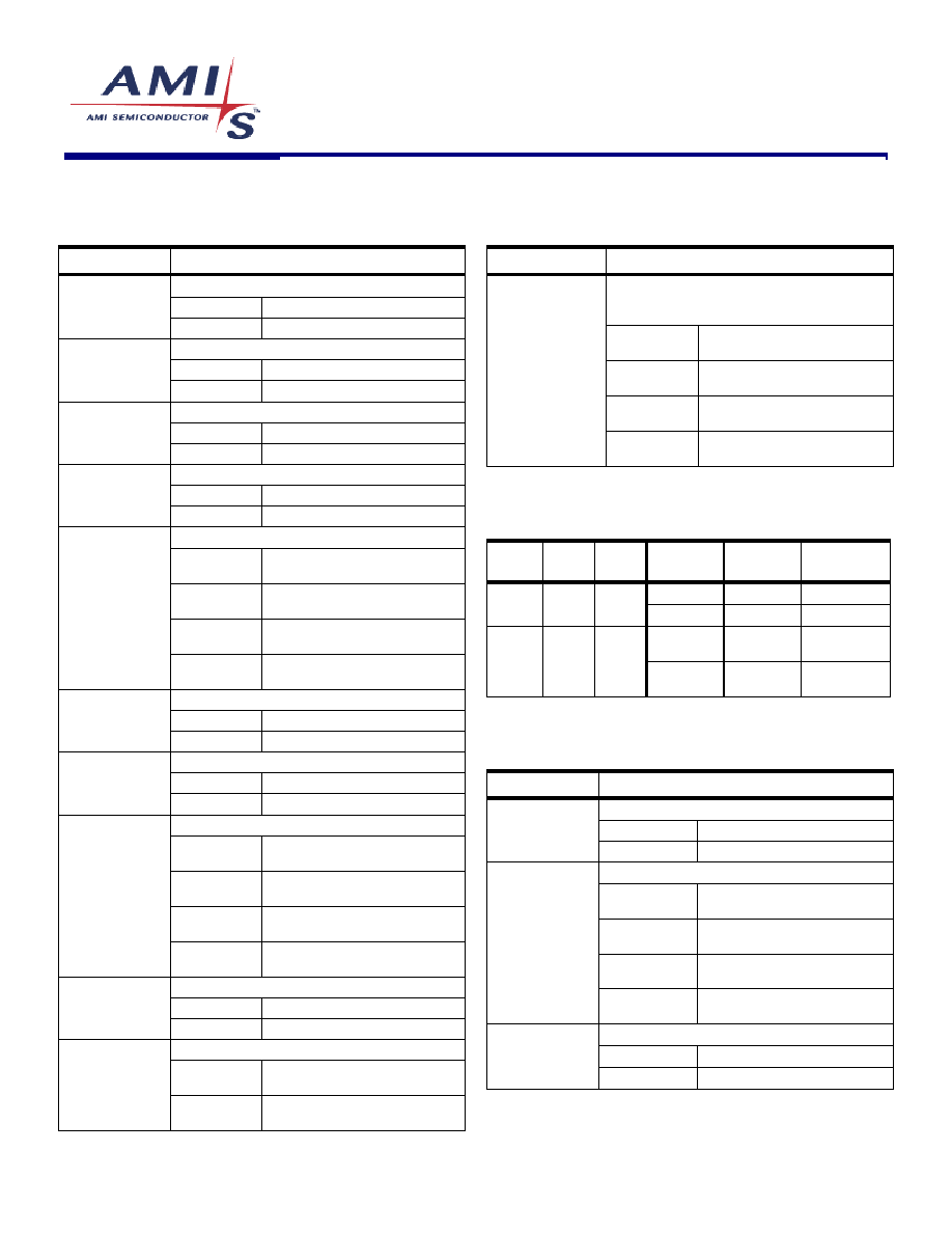
Table 1: Pin Descriptions
Key: AI = Analog Input; AO = Analog Output; DI = Digital Input; DI
U
= Input with Internal Pull-Up; DI
D
= Input with Internal Pull-Down; DIO = Digital Input/Output; DI-3 = Three-Level Digital Input,
DO = Digital Output; P = Power/Ground; # = Active Low pin
PIN
TYPE
NAME
DESCRIPTION
1
DI
SCL
Serial Interface Clock (requires an external pull-up)
2
DIO
SDA
Serial Interface Data Input/Output (requires an external pull-up)
3
DI
ADDR
Address Select Bit (see Section 5.2.1)
4
P
VSS
Ground
5
AI
XIN
VCXO Feedback
6
AO
XOUT
VCXO Drive
7
AI
XTUNE
VCXO Tune
8
P
VDD
Power Supply (+5V)
9
DIO
LOCK/IPRG
Lock Indicator / PECL Current Drive Programming
10
AI
EXTLF
External Loop Filter
11
P
VSS
Ground
12
DI
REF
Reference Frequency Input
13
DI
FBK
Feedback Input
14
P
VDD
Power Supply (+5V)
15
DO
CLKP
Differential Clock Output (+)
16
DO
CLKN
Differential Clock Output (-)
4.0
Functional Block Description
4.1
Main Loop PLL
The Main Loop Phase Locked Loop (ML-PLL) is a stan-
dard phase- and frequency- locked loop architecture. As
shown in Figure 2, the ML-PLL consists of a Reference
Divider, a Phase-Frequency Detector (PFD), a charge
pump, an internal loop filter, a Voltage-Controlled Oscil-
lator (VCO), a Feedback Divider, and a Post Divider.
During operation, the reference frequency (f
REF
), gener-
ated by either the on-board crystal oscillator or an exter-
nal frequency source, is first reduced by the Reference
Divider. The integer value that the frequency is divided by
is called the modulus, and is denoted as N
R
for the Ref-
erence Divider. The divided reference is then fed into the
PFD.
The PFD controls the frequency of the VCO (f
VCO
)
through the charge pump and loop filter. The VCO pro-
vides a high-speed, low noise, continuously variable fre-
quency clock source for the ML-PLL. The output of the
VCO is fed back to the PFD through the Feedback Di-
vider (the modulus is denoted by N
F
) to close the loop.
The PFD will drive the VCO up or down in frequency until
the divided reference frequency and the divided VCO
frequency appearing at the inputs of the PFD are equal.
The input/output relationship between the reference fre-
quency and the VCO frequency is
R
REF
F
VCO
N
f
N
f
=
.
If the VCO frequency is used as the PLL output fre-
quency (f
CLK
) then the basic PLL equation can be rewrit-
ten as
˜
˜
¯
ˆ
Á
Á
Ë
Ê
=
R
F
REF
CLK
N
N
f
f
.
4.1.1 Reference
Divider
The Reference Divider is designed for low phase jitter.
The divider accepts either the output of either the Crystal
Loop (the VCXO output) or an external reference fre-
quency, and provides a divided-down frequency to the
PFD. The Reference Divider is a 12-bit divider, and can
be programmed for any modulus from 1 to 4095. See
both Table 3 and Table 8 for additional programming in-
formation.

3
FS6131-01
FS6131-01
FS6131-01
FS6131-01
Programmable Line Lock Clock Generator IC
Programmable Line Lock Clock Generator IC
Programmable Line Lock Clock Generator IC
Programmable Line Lock Clock Generator IC
4.1.2 Feedback
Divider
The Feedback Divider is based on a dual-modulus
prescaler technique. The technique allows the same
granularity as a fully programmable feedback divider,
while still allowing the programmable portion to operate at
low speed. A high-speed pre-divider (also called a
prescaler) is placed between the VCO and the program-
mable Feedback Divider because of the high speeds at
which the VCO can operate. The dual-modulus technique
insures reliable operation at any speed that the VCO can
achieve and reduces the overall power consumption of
the divider.
For example, a fixed divide-by-eight could be used in the
Feedback Divider. Unfortunately, a divide-by-eight would
limit the effective modulus of the feedback divider path to
multiples of eight. The limitation would restrict the ability
of the PLL to achieve a desired input-frequency-to-
output-frequency ratio without making both the Reference
and Feedback Divider values comparatively large. Large
divider moduli are generally undesirable due to increased
phase jitter.
Figure 3: Feedback Divider
Dual-
Modulus
Prescaler
A
Counter
M
Counter
f
vco
To understand the operation, refer to Figure 3. The M-
counter (with a modulus of M) is cascaded with the dual-
modulus prescaler. If the prescaler modulus were fixed at
N, the overall modulus of the feedback divider chain
would be M
◊
N. However, the A-counter causes the
prescaler modulus to be altered to N+1 for the first A out-
puts of the prescaler. The A-counter then causes the
dual-modulus prescaler to revert to a modulus of
N
until
the M-counter reaches its terminal state and resets the
entire divider. The overall modulus can be expressed as
)
(
)
1
(
A
M
N
N
A
-
+
+
,
where M
A, which simplifies to
A
N
M
+
◊
.
4.1.3 Feedback
Divider
Programming
The requirement that M
A means that the Feedback Di-
vider can only be programmed for certain values below a
divider modulus of 56. The selection of divider values is
listed in Table 2.
If the desired Feedback Divider is less than 56, find the
divider value in the table. Follow the column up to find the
A-counter program value. Follow the row to the left to find
the M-counter value.
Above a modulus of 56, the Feedback Divider can be
programmed to any value up to 16383. See both Table 3
and Table 8 for additional programming information.
Table 2: Feedback Modulus Below 56
A-COUNTER: FBKDIV[2:0]
M-COUNTER:
FBKDIV[13:3]
000
001
010
011
100
101
110
111
00000000001
8
9
-
-
-
-
-
-
00000000010
16
17
18
-
-
-
-
-
00000000011
24
25
26
27
-
-
-
-
00000000100
32
33
34
35
36
-
-
-
00000000101
40
41
42
43
44
45
-
-
00000000110
48
49
50
51
52
53
54
-
00000000111
56
57
58
59
60
61
62
63
FEEDBACK DIVIDER MODULUS
4.1.4 Post
Divider
The Post Divider consists of three individually program-
mable dividers, as shown in Figure 4.
Figure 4: Post Divider
Post
Divider 1
(N
P1
)
Post
Divider 2
(N
P2
)
Post
Divider 3
(N
P3
)
POST3[1:0]
POST2[1:0]
POST1[1:0]
POST DIVIDER (N
Px
)
f
out
f
GBL
The moduli of the individual dividers are denoted as N
P1
,
N
P2
, and N
P3
, and together they make up the array
modulus N
Px
.
3
2
1
P
P
P
Px
N
N
N
N
◊
◊
=

4
FS6131-01
FS6131-01
FS6131-01
FS6131-01
Programmable Line Lock Clock Generator IC
Programmable Line Lock Clock Generator IC
Programmable Line Lock Clock Generator IC
Programmable Line Lock Clock Generator IC
The Post Divider performs several useful functions. First,
it allows the VCO to be operated in a narrower range of
speeds compared to the variety of output clock speeds
that the device is required to generate. Second, it
changes the basic PLL equation to
˜
˜
¯
ˆ
Á
Á
Ë
Ê
˜
˜
¯
ˆ
Á
Á
Ë
Ê
=
Px
R
F
REF
CLK
N
N
N
f
f
1
.
The extra integer in the denominator permits more flexi-
bility in the programming of the loop for many applica-
tions where frequencies must be achieved exactly.
Note that a nominal 50/50 duty factor is preserved for
selections which have an odd modulus.
4.2
Phase Adjust and Sampling
In line-locked or genlocked applications, it is necessary to
know the exact phase relation of the output clock relative
to the input clock. Since the VCO is included within the
feedback loop in a simple PLL structure, the VCO output
is exactly phase aligned with the input clock. Every cycle
of the input clock equals N
R
/N
F
cycles of the VCO clock.
Figure 5: Simple PLL
Phase
Frequency
Detect
Feedback
Divider (N
F
)
VCO
f
IN
f
OUT
Reference
Divider (N
R
)
f
IN
f
OUT
The addition of a Post Divider, while adding flexibility,
makes the phase relation between the input and output
clock unknown because the Post Divider is outside the
feedback loop.
Figure 6: PLL with Post Divider
Phase
Frequency
Detect
Feedback
Divider (N
F
)
VCO
f
IN
f
OUT
Reference
Divider (N
R
)
f
IN
f
VCO
Post
Divider (N
F
)
f
VCO
f
OUT
?
4.2.1
Clock Gobbler (Phase Adjust)
The Clock Gobbler circuit takes advantage of the un-
known relationship between input and output clocks to
permit the adjustment of the CLKP/CLKN output clock
phase relative to the REF input. The Clock Gobbler circuit
removes a VCO clock pulse before the pulse clocks the
Post Divider. In this way, the phase of the output clock
can be slipped until the output phase is aligned with the
input clock phase.
To adjust the phase relationship, switch the Feedback
Divider source to the Post Divider input via the
FBKDSRC bit, and toggle the GBL register bit. The Clock
Gobbler output clock is delayed by one VCO clock period
for each transition of the GBL bit from zero to one.
4.2.2 Phase
Alignment
To maintain a fixed phase relation between input and
output clocks, the Post Divider must be placed inside the
feedback loop. The source for the Feedback Divider is
obtained from the output of the Post Divider via the
FBKDSRC switch. In addition, the Feedback Divider must
be dividing at a multiple of the Post Divider.
Figure 7: Aligned I/O Phase
Phase
Frequency
Detect
Feedback
Divider (N
F
)
VCO
f
IN
f
OUT
Reference
Divider (N
R
)
Post
Divider (N
F
)
f
IN
f
OUT
4.2.3
Phase Sampling and Initial Alignment
However, the ability to adjust the phase is useless with-
out knowing the initial relation between output and input
phase. To aid in the initial synchronization of the output
phase to input phase, a Phase Align "flag" makes a tran-
sition (zero to one or one to zero) when the output clock
phase becomes aligned with the feedback source phase.
The feedback source clock is, by definition, locked to the
input clock phase.
First, the FS6131 is used to sample the output clock with
the feedback source clock and set/clear the Phase Align
flag when the two clocks match to within a feedback
source clock period. Then, the Clock Gobbler is used to
delay the output phase relative to the input phase one
VCO clock at a time until a transition on the flag occurs.
When a transition occurs, the output and input clocks are
phase aligned.

5
FS6131-01
FS6131-01
FS6131-01
FS6131-01
Programmable Line Lock Clock Generator IC
Programmable Line Lock Clock Generator IC
Programmable Line Lock Clock Generator IC
Programmable Line Lock Clock Generator IC
To enter this mode, set STAT[1] to one and clear
STAT[0] to zero. If the CMOS bit is set to one, the
LOCK/IPRG pin can display the flag. The flag is always
available under software control by reading back the
STAT[1] bit, which will be overwritten by the flag in this
mode.
4.2.4 Feedback
Divider
Monitoring
The Feedback Divider clock can be brought out the
LOCK/IPRG pin independent of the output clock to allow
monitoring of the Feedback Divider clock. To enter this
mode, set both the STAT[1] and STAT[0] bits to one. The
CMOS bit must also be set to one to enable the
LOCK/IPRG pin as an output.
4.3
Loop Gain Analysis
For applications where an external loop filter is required,
the following analysis example can be used to determine
loop gain and stability.
The loop gain of a PLL is the product of all of the gains
within the loop.
Establish the basic operating parameters:
Set the charge pump current:
A
I
chgpump
µ
10
=
Set the loop filter values:
pF
C
F
C
k
R
LF
220
015
.
0
15
2
1
=
=
=
µ
Set the VCO gain (VCOSPD):
V
MHz
A
VCO
/
230
=
Set the Feedback Divider:
3500
=
F
N
Set the Reference frequency (at the input to the Phase
Detector:
kHz
f
REF
20
=
The transfer function of the Phase Detector and Charge
Pump combination is (in A/rad):
2
chgpump
PD
I
K
=
The transfer function of the loop filter is (in V/A):
˜
˜
˜
˜
¯
ˆ
Á
Á
Á
Á
Ë
Ê
˜
¯
ˆ
Á
Ë
Ê
+
+
=
1
2
1
1
1
)
(
sC
R
sC
s
K
LF
LF
The VCO transfer function (in rad/s, and accounting for
the phase integration that occurs in the VCO) is:
s
A
s
K
VCO
VCO
1
2
)
(
=
The transfer function of the Feedback Divider is:
F
F
N
K
1
=
Finally, the sampling effect that occurs in the Phase De-
tector is accounted for by:
REF
f
s
SAMP
f
s
e
s
K
REF
˜
˜
˜
¯
ˆ
Á
Á
Á
Ë
Ê
-
=
˜
¯
ˆ
Á
Ë
Ê
-
1
)
(
The loop gain of the PLL is:
)
(
)
(
)
(
)
(
s
K
K
s
K
s
K
K
s
K
SAMP
F
VCO
LF
PD
LOOP
=
Figure 8: Loop Gain vs. Frequency
0.01
Frequency (f
i
)
0.1
0.1kHz
1kHz
10kHz
100kHz
1
10
100
Amp
litu
d
e

6
FS6131-01
FS6131-01
FS6131-01
FS6131-01
Programmable Line Lock Clock Generator IC
Programmable Line Lock Clock Generator IC
Programmable Line Lock Clock Generator IC
Programmable Line Lock Clock Generator IC
The loop phase angle is:
[
]
)
2
(
arg
i
LOOP
i
f
j
K
=
.
Figure 9: Loop Phase vs. Frequency
-150∞
Frequency (f
i
)
-100∞
P
has
e
0.1kHz
1kHz
10kHz
100kHz
A Nyquist plot of gain vs. amplitude is shown below.
Figure 10: Loop Nyquist Plot
45∞
0∞
315∞
270∞
225∞
180∞
135∞
90∞
0.2
0.4
0.6
0.8
1.0
Phase
Amplitude
1.2
Gain Margin
Phase
Margin
4.4
Voltage-Controlled Crystal Oscillator
The VCXO provides a tunable, low-jitter frequency refer-
ence for the rest of the FS6131 system components.
Loading capacitance for the crystal is internal to the de-
vice. No external components (other than the resonator
itself) are required for operation of the VCXO.
The resonator loading capacitance is adjustable under
register control. This feature permits factory coarse tun-
ing of inexpensive resonators to the necessary precision
for digital video applications. Continuous fine-tuning of
the VCXO frequency is accomplished by varying the volt-
age on the XTUNE pin. The total change (from one ex-
treme to the other) in effective loading capacitance is
1.5pF nominal, and the effect is shown in Figure 11. The
oscillator operates the crystal resonator in the parallel-
resonant mode. Crystal warping, or the "pulling" of the
crystal oscillation frequency, is accomplished by altering
the effective load capacitance presented to the crystal by
the oscillator circuit. The actual amount that changing the
load capacitance alters the oscillator frequency will be
dependent on the characteristics of the crystal as well as
the oscillator circuit itself.
The motional capacitance of the crystal (usually referred
to by crystal manufacturers as C
1
), the static capacitance
of the crystal (C
0
), and the load capacitance (C
L
) of the
oscillator determine the warping capability of the crystal
in the oscillator circuit. A simple formula to determine the
total warping capability of a crystal is
(
)
(
) (
)
C
C
C
C
C
C
C
ppm
f
L
L
L
L
1
0
2
0
6
1
2
1
2
10
)
(
+
◊
+
◊
◊
-
◊
=
,
where C
L1
and C
L2
are the two extremes of the applied
load capacitance obtained from Table 11.
Example: A crystal with the following parameters is used
with the FS6131. The total coarse tuning range is:
C
1
=0.02pF, C
0
=5.0pF, C
L1
=10.0pF, C
L2
=22.66pF
(
)
(
) (
)
ppm
.
.
.
f
305
10
5
66
22
5
2
10
10
66
22
02
0
6
=
+
◊
+
◊
◊
-
◊
=

7
FS6131-01
FS6131-01
FS6131-01
FS6131-01
Programmable Line Lock Clock Generator IC
Programmable Line Lock Clock Generator IC
Programmable Line Lock Clock Generator IC
Programmable Line Lock Clock Generator IC
4.4.1 VCXO
Tuning
The VCXO may be coarse tuned by a programmable ad-
justment of the crystal load capacitance via the XCT[3:0]
control bits. See Table 11 for the control code and the
associated loading capacitance.
The actual amount of frequency warping caused by the
tuning capacitance will depend on the crystal used. The
VCXO tuning capacitance includes an external 6pF load
capacitance (12pF from the XIN pin to ground and 12pF
from the XOUT pin to ground). The fine tuning capability
of the VCXO can be enabled by setting the XLVTEN bit
to a one, or disabled by setting it to a zero.
Figure 11 shows the typical effect of the coarse and fine
tuning mechanisms. The total coarse tune range is about
350ppm. The difference in VCXO frequency in parts per
million (ppm) is shown as the fine tuning voltage on the
XTUNE pin varies from 0V to 5V. Note that as the crystal
load capacitance is increased the VCXO frequency is
pulled somewhat less with each coarse step, and the fine
tuning range decreases. The fine tuning range always
overlaps a few coarse tuning ranges, eliminating the pos-
sibility of holes in the VCXO response. The different
crystal warping characteristics may change the scaling on
the Y-axis, but not the overall characteristic of the curves.
Figure 11: VCXO Coarse and Fine Tuning
VCXO Range (ppm) vs. XTUNE Voltage (V)
-200
-150
-100
-50
0
50
100
150
200
0
1
2
3
4
5
6
7
8
9 10 11 12 13 14 15
Coarse Tune Setting XCT[3:0]
V
C
X
O
Range (
ppm
)
XTUNE Voltage = 0.0V
XTUNE Voltage = 5.0V
4.5 Crystal
Loop
The Crystal Loop is designed to attenuate the jitter on a
highly jittered, low-Q, low frequency reference. The
Crystal Loop can also maintain a constant frequency out-
put into the Main Loop if the low frequency reference is
intermittent.
The Crystal Loop consists of a Voltage-Controllable
Crystal Oscillator (VCXO), a divider, a PFD, and a charge
pump that tunes the VCXO to a frequency reference. The
frequency reference is phase-locked to the divided fre-
quency of an external, high-Q, jitter-free crystal, thereby
locking the VCXO to the reference frequency. The VCXO
can continue to run off the crystal even if the frequency
reference becomes intermittent.
4.5.1
Locking to an External Frequency Source
When the Crystal Loop is synchronized to an external
frequency source, the FS6131 can monitor the Crystal
Loop and detect if the loop unlocks from the external
source. The Crystal Loop tries to drive to zero frequency
if the external source is dropped, and sets a Lock Status
error flag.
The Crystal Loop can also detect if the VCXO has
dropped out of the Fine Tune range, requiring a change
to the Coarse Tune. The Lock Status also latches the
direction the loop went out of range (high or low) when
the loop became unlocked.
4.5.1.1 Crystal Loop Lock Status Flag
To enable this mode, clear the STAT[1] and STAT[0] bits
to zero. If the CMOS bit is set to one, the LOCK/IPRG pin
will be low if the Crystal Loop becomes unlocked. The
flag is always available under software control by reading
back the STAT[1] bit, which is overwritten with a the
status flag (low = unlocked) in this mode (see Table 6).

8
FS6131-01
FS6131-01
FS6131-01
FS6131-01
Programmable Line Lock Clock Generator IC
Programmable Line Lock Clock Generator IC
Programmable Line Lock Clock Generator IC
Programmable Line Lock Clock Generator IC
4.5.1.2 Out-Of-Range
High/Low
The direction the loop has gone out-of-range can be de-
termined by clearing STAT[1] to zero and setting STAT[0]
bit to one. If the CMOS bit is set to one, the LOCK/IPRG
pin will go high if the Crystal Loop went out of range high.
If the pin goes to a logic-low, the loop went out of range
low.
The out-of-range information is also available under soft-
ware control by reading back the STAT[1] bit, which is
overwritten by the flag (high = out-of-range high, low =
out-of-range low) in this mode. The bit is set or cleared
only if the Crystal Loop loses lock (see Table 6).
4.5.1.3 Crystal
Loop
Disable
The Crystal Loop is disabled by setting the XLPDEN bit
to a logic-high (1). The bit disables the charge pump cir-
cuit in the loop.
Setting the XLPDEN bit low (0) permits the crystal loop to
operate as a control loop.
4.6
Connecting the FS6131 to an
External Reference Frequency
If a crystal oscillator is not used, tie XIN to ground and
shut down the crystal oscillator by setting XLROM[2:0]=1.
The REF and FBK pins do not have pull-up or pull-down
current, but do have a small amount of hysteresis to re-
duce the possibility of extra edges. Signals may be AC-
coupled into these inputs with an external DC-bias circuit
to generate a DC-bias of 2.5V. Any Reference or Feed-
back signal should be square for best results, and the
signals should be rail-to-rail. Unused inputs should be
grounded to avoid unwanted signal injection.
4.7
Differential Output Stage
The differential output stage supports both CMOS and
pseudo-ECL (PECL) signals. The desired output interface
is chosen via the program registers (see Table 4).
If a PECL interface is used, the transmission line is usu-
ally terminated using a ThÈvenin termination. The output
stage can only sink current in the PECL mode, and the
amount of sink current is set by a programming resistor
on the LOCK/IPRG pin. The ratio of IPRG current to out-
put drive current is shown in Figure 12. Source current is
provided by the pull-up resistor that is part of the
ThÈvenin termination.
Figure 12: IPRG to CLKP/CLKN Current
0.0
5.0
10.0
15.0
20.0
25.0
0
20
40
60
80
CLKP/CLKN PECL Output Current (mA)
IP
R
G
Input
C
u
rrent
(
m
A
)

9
FS6131-01
FS6131-01
FS6131-01
FS6131-01
Programmable Line Lock Clock Generator IC
Programmable Line Lock Clock Generator IC
Programmable Line Lock Clock Generator IC
Programmable Line Lock Clock Generator IC
5.0 I
2
C-bus Control Interface
This device is a read/write slave device
meeting all Philips I
2
C-bus specifications
except a "general call." The bus has to be
controlled by a master device that generates
the serial clock SCL, controls bus access, and generates
the START and STOP conditions while the device works
as a slave. Both master and slave can operate as a
transmitter or receiver, but the master device determines
which mode is activated. A device that sends data onto
the bus is defined as the transmitter, and a device re-
ceiving data as the receiver.
I
2
C-bus logic levels noted herein are based on a percent-
age of the power supply (V
DD
). A logic-one corresponds
to a nominal voltage of V
DD
, while a logic-zero corre-
sponds to ground (V
SS
).
5.1 Bus
Conditions
Data transfer on the bus can only be initiated when the
bus is not busy. During the data transfer, the data line
(SDA) must remain stable whenever the clock line (SCL)
is high. Changes in the data line while the clock line is
high will be interpreted by the device as a START or
STOP condition. The following bus conditions are defined
by the I
2
C-bus protocol.
5.1.1 Not
Busy
Both the data (SDA) and clock (SCL) lines remain high to
indicate the bus is not busy.
5.1.2
START Data Transfer
A high to low transition of the SDA line while the SCL in-
put is high indicates a START condition. All commands to
the device must be preceded by a START condition.
5.1.3
STOP Data Transfer
A low to high transition of the SDA line while SCL is held
high indicates a STOP condition. All commands to the
device must be followed by a STOP condition.
5.1.4 Data
Valid
The state of the SDA line represents valid data if the SDA
line is stable for the duration of the high period of the SCL
line after a START condition occurs. The data on the
SDA line must be changed only during the low period of
the SCL signal. There is one clock pulse per data bit.
Each data transfer is initiated by a START condition and
terminated with a STOP condition. The number of data
bytes transferred between START and STOP conditions
is determined by the master device, and can continue
indefinitely. However, data that is overwritten to the de-
vice after the first eight bytes will overflow into the first
register, then the second, and so on, in a first-in, first-
overwritten fashion.
5.1.5 Acknowledge
When addressed, the receiving device is required to gen-
erate an Acknowledge after each byte is received. The
master device must generate an extra clock pulse to co-
incide with the Acknowledge bit. The acknowledging de-
vice must pull the SDA line low during the high period of
the master acknowledge clock pulse. Setup and hold
times must be taken into account.
The master must signal an end of data to the slave by not
generating and acknowledge bit on the last byte that has
been read (clocked) out of the slave. In this case, the
slave must leave the SDA line high to enable the master
to generate a STOP condition.
5.2 I
2
C-bus Operation
All programmable registers can be accessed randomly or
sequentially via this bi-directional two wire digital inter-
face. The crystal oscillator does not have to run for com-
munication to occur.
The device accepts the following I
2
C-bus commands:
5.2.1 Slave
Address
After generating a START condition, the bus master
broadcasts a seven-bit slave address followed by a R/W
bit. The address of the device is:
A6
A5
A4
A3
A2
A1
A0
1
0
1
1
X
0
0
where X is controlled by the logic level at the ADDR pin.
The variable ADDR bit allows two different FS6131 de-
vices to exist on the same bus. Note that every device on
an I
2
C-bus must have a unique address to avoid bus
conflicts. The default address sets A2 to 0 via the pull-
down on the ADDR pin.

10
FS6131-01
FS6131-01
FS6131-01
FS6131-01
Programmable Line Lock Clock Generator IC
Programmable Line Lock Clock Generator IC
Programmable Line Lock Clock Generator IC
Programmable Line Lock Clock Generator IC
5.2.2
Random Register Write Procedure
Random write operations allow the master to directly
write to any register. To initiate a write procedure, the
R/W bit that is transmitted after the seven-bit device ad-
dress is a logic-low. This indicates to the addressed slave
device that a register address will follow after the slave
device acknowledges its device address. The register
address is written into the slave's address pointer. Fol-
lowing an acknowledge by the slave, the master is al-
lowed to write eight bits of data into the addressed regis-
ter. A final acknowledge is returned by the device, and
the master generates a STOP condition.
If either a STOP or a repeated START condition occurs
during a Register Write, the data that has been trans-
ferred is ignored.
5.2.3
Random Register Read Procedure
Random read operations allow the master to directly read
from any register. To perform a read procedure, the R/W
bit that is transmitted after the seven-bit address is a
logic-low, as in the Register Write procedure. This indi-
cates to the addressed slave device that a register ad-
dress will follow after the slave device acknowledges its
device address. The register address is then written into
the slave's address pointer.
Following an acknowledge by the slave, the master gen-
erates a repeated START condition. The repeated
START terminates the write procedure, but not until after
the slave's address pointer is set. The slave address is
then resent, with the R/W bit set this time to a logic-high,
indicating to the slave that data will be read. The slave
will acknowledge the device address, and then transmits
the eight-bit word. The master does not acknowledge the
transfer but does generate a STOP condition.
5.2.4
Sequential Register Write Procedure
Sequential write operations allow the master to write to
each register in order. The register pointer is automati-
cally incremented after each write. This procedure is
more efficient than the Random Register Write if several
registers must be written.
To initiate a write procedure, the R/W bit that is transmit-
ted after the seven-bit device address is a logic-low. This
indicates to the addressed slave device that a register
address will follow after the slave device acknowledges
its device address. The register address is written into the
slave's address pointer. Following an acknowledge by the
slave, the master is allowed to write up to eight bytes of
data into the addressed register before the register ad-
dress pointer overflows back to the beginning address.
An acknowledge by the device between each byte of data
must occur before the next data byte is sent.
Registers are updated every time the device sends an
acknowledge to the host. The register update does not
wait for the STOP condition to occur. Registers are
therefore updated at different times during a Sequential
Register Write.
5.2.5
Sequential Register Read Procedure
Sequential read operations allow the master to read from
each register in order. The register pointer is automati-
cally incremented by one after each read. This procedure
is more efficient than the Random Register Read if sev-
eral registers must be read.
To perform a read procedure, the R/W bit that is trans-
mitted after the seven-bit address is a logic-low, as in the
Register Write procedure. This indicates to the addressed
slave device that a register address will follow after the
slave device acknowledges its device address. The reg-
ister address is then written into the slave's address
pointer.
Following an acknowledge by the slave, the master gen-
erates a repeated START condition. The repeated
START terminates the write procedure, but not until after
the slave's address pointer is set. The slave address is
then resent, with the R/W bit set this time to a logic-high,
indicating to the slave that data will be read. The slave
will acknowledge the device address, and then transmits
all eight bytes of data starting with the initial addressed
register. The register address pointer will overflow if the
initial register address is larger than zero. After the last
byte of data, the master does not acknowledge the
transfer but does generate a STOP condition.

11
FS6131-01
FS6131-01
FS6131-01
FS6131-01
Programmable Line Lock Clock Generator IC
Programmable Line Lock Clock Generator IC
Programmable Line Lock Clock Generator IC
Programmable Line Lock Clock Generator IC
Figure 13: Random Register Write Procedure
A
A
DATA
W A
From bus host
to device
S
REGISTER ADDRESS
P
From device
to bus host
DEVICE ADDRESS
Register Address
Acknowledge
STOP Condition
Data
Acknowledge
Acknowledge
START
Command
WRITE Command
7-bit Receive
Device Address
Figure 14: Random Register Read Procedure
A
R
A
A
A
W
S
REGISTER ADDRESS
P
S
DEVICE ADDRESS
START
Command
WRITE Command
Acknowledge
Register Address
Acknowledge
READ Command
Acknowledge
Data
NO Acknowledge
STOP Condition
From bus host
to device
From device
to bus host
7-bit Receive
Device Address
7-bit Receive
Device Address
DEVICE ADDRESS
DATA
Repeat START
Figure 15: Sequential Register Write Procedure
A
A
A
W
S
P
START
Command
WRITE Command
Acknowledge
Register Address
Acknowledge
Data
Data
Acknowledge
Data
STOP Command
Acknowledge
Acknowledge
From bus host
to device
From device
to bus host
7-bit Receive
Device Address
DEVICE ADDRESS
A
A
REGISTER ADDRESS
DATA
DATA
DATA
Figure 16: Sequential Register Read Procedure
A
W
S
START
Command
WRITE Command
Acknowledge
Register Address
Acknowledge
Data
Acknowledge
Data
STOP Command
Acknowledge
READ Command
NO Acknowledge
From bus host
to device
From device
to bus host
7-bit Receive
Device Address
7-bit Receive
Device Address
DEVICE ADDRESS
A
A
REGISTER ADDRESS
A
R
A P
S
DEVICE ADDRESS
DATA
DATA
Repeat START

12
FS6131-01
FS6131-01
FS6131-01
FS6131-01
Programmable Line Lock Clock Generator IC
Programmable Line Lock Clock Generator IC
Programmable Line Lock Clock Generator IC
Programmable Line Lock Clock Generator IC
6.0 Programming
Information
All register bits are cleared to zero on power-up. All register bits may be read back as written except STAT[1] (Bit 63).
Table 3: Register Map
ADDRESS
BIT 7
BIT 6
BIT 5
BIT 4
BIT 3
BIT 2
BIT 1
BIT 0
STAT[1]
(Bit 63)
STAT[0]
(Bit 62)
XLVTEN
(Bit 61)
CMOS
(Bit 60)
XCT[3]
(Bit 59)
XCT[2]
(Bit 58)
XCT[1]
(Bit 57)
XCT[0]
(Bit 56)
00 = Crystal Loop ≠ Lock Status
01 = Crystal Loop ≠ Out of Range
0 = Fine Tune
Inactive
0 = PECL
10 = Main Loop ≠ Phase Status
BYTE 7
11 = Feedback Divider Output
1 = Fine Tune
Active
1 = CMOS, Lock
Status
VCXO Coarse Tune
See Table 11
XLPDEN
(Bit 55)
XLSWAP
(Bit 54)
XLCP[1]
(Bit 53)
XLCP[0]
(Bit 52)
XLROM[2]
(Bit 51)
XLROM[1]
(Bit 50)
XLROM[0]
(Bit 49)
GBL
(Bit 48)
00 = 1.5
µ
A
0 = Crystal Loop
Operates
0 = Use with
External VCXO
01 = 5
µ
A
0 = No Clock
Phase Adjust
10 = 8
µ
A
BYTE 6
1 = Crystal Loop
Powered Down
1 = Use with
Internal VCXO
11 = 24
µ
A
Crystal Loop Control
See Table 10
1 = Clock Phase
Delay
OUTMUX[1]
(Bit 47)
OUTMUX[0]
(Bit 46)
OSCTYPE
(Bit 45)
VCOSPD
(Bit 44)
LFTC
(Bit 43)
EXTLF
(Bit 42)
MLCP[1]
(Bit 41)
MLCP[0]
(Bit 40)
00 = VCO Output
00 = 1.5
µ
A
01 = Reference Divider Output
0 = Low Phase
Jitter Oscillator
0 = High Speed
Range
0 = Short Time
Constant
0 = Internal Loop
Filter
01 = 5
µ
A
10 = Phase Detector Input
10 = 8
µ
A
BYTE 5
11 = VCXO Output
1 = FS6031
Oscillator
1 = Low Speed
Range
1 = Long Time
Constant
1 = External Loop
Filter
11 = 24
µ
A
FBKDSRC[1]
(Bit 39)
FBKDSRC[0]
(Bit 38)
FBKDIV[13]
(Bit 37)
FBKDIV[12]
(Bit 36)
FBKDIV[11]
(Bit 35)
FBKDIV[10]
(Bit 34)
FBKDIV[9]
(Bit 33)
FBKDIV[8]
(Bit 32)
00 = Post Divider Output
01 = FBK Pin
8192
4096
2048
1024
512
256
10 = Post Divider Input
BYTE 4
11 = FBK Pin
M Counter
FBKDIV[7]
(Bit 31)
FBKDIV[6]
(Bit 30)
FBKDIV[5]
(Bit 29)
FBKDIV[4]
(Bit 28)
FBKDIV[3]
(Bit 27)
FBKDIV[2]
(Bit 26)
FBKDIV[1]
(Bit 25)
FBKDIV[0]
(Bit 24)
128
64
32
16
8
4
2
1
BYTE 3
M Counter
A Counter ≠ See Table 2
POST3[1]
(Bit 21)
POST3[1]
(Bit 20)
POST2[1]
(Bit 19)
POST2[0]
(Bit 18)
POST1[1]
(Bit 17)
POST1[0]
(Bit 16)
00 = Divide by 1
00 = Divide by 1
00 = Divide by 1
01 = Divide by 3
01 = Divide by 3
01 = Divide by 2
10 = Divide by 5
10 = Divide by 5
10 = Divide by 4
BYTE 2
Reserved (0)
Reserved (0)
11 = Divide by 4
11 = Divide by 4
11 = Divide by 8
PDFBK
(Bit 15)
PDREF
(Bit 14)
SHUT
(Bit 13)
REFDSRC
(Bit 12)
REFDIV[11]
(Bit 11)
REFDIV[10]
(Bit 10)
REFDIV[9]
(Bit 9)
REFDIV[8]
(Bit 8)
0 = Feedback
Divider
0 = Reference
Divider
0 = Main Loop
Operates
0 = VCXO
BYTE 1
1 = FBK Pin
1 = REF Pin
1 = Main Loop
Powered Down
1 = Ref Pin
2048
1024
512
256
REFDIV[7]
(Bit 7)
REFDIV[6]
(Bit 6)
REFDIV[5]
(Bit 5)
REFDIV[4]
(Bit 4)
REFDIV[3]
(Bit 3)
REFDIV[2]
(Bit 2)
REFDIV[1]
(Bit 1)
REFDIV[0]
(Bit 0)
BYTE 0
128
64
32
16
8
4
2
1
13
FS6131-01
FS6131-01
FS6131-01
FS6131-01
Programmable Line Lock Clock Generator IC
Programmable Line Lock Clock Generator IC
Programmable Line Lock Clock Generator IC
Programmable Line Lock Clock Generator IC
Table 4: Device Configuration Bits
NAME
DESCRIPTION
REFerence Divider SouRCe
Bit = 0
Crystal Oscillator (VCXO)
REFDSRC
(Bit 12)
Bit = 1
REF pin
main loop SHUT down select
Bit = 0
Disabled (main loop operates)
SHUT
(Bit 13)
Bit = 1
Enabled (main loop shuts down)
Phase Detector REFerence source
Bit = 0
Reference Divider
PDREF
(Bit 14)
Bit = 1
REF pin
Phase Detector FeedBacK source
Bit = 0
Feedback Divider
PDFBK
(Bit 15)
Bit = 1
FBK pin
FeedBacK Divider SouRCe
Bit 39 = 0
Bit 38 = 0
Post Divider Output
Bit 39 = 0
Bit 38 = 1
FBK pin
Bit 39 = 1
Bit 38 = 0
VCO Output (Post Divider Input)
FBKDSRC[1:0]
(Bits 39-38)
Bit 39 = 1
Bit 38 = 1
FBK pin
EXTernal Loop Filter select
Bit = 0
Internal Loop Filter
EXTLF
(Bit 42)
Bit = 1
EXTLF pin
OSCillator TYPe
Bit = 0
Low Phase Jitter Oscillator
OSCTYPE
(Bit 45)
Bit = 1
FS6031 Compatible Oscillator
OUTput MUltipleXer select
Bit 47 = 0
Bit 46 = 0
Main Loop PLL (VCO Output)
Bit 47 = 0
Bit 46 = 1
Reference Divider Output
Bit 47 = 1
Bit 46 = 0
Phase Detector Input
OUTMUX[1:0]
(Bits 47-46)
Bit 47 = 1
Bit 46 = 1
VCXO Output
clock GobBLer control
Bit = 0
No Clock Phase Adjust
GBL
(Bit 48)
Bit = 1
Clock Phase Delay
CLKP/CLKN output mode
Bit = 0
PECL Output
(positive-ECL output drive)
CMOS
(Bit 60)
Bit = 1
CMOS Output /
Lock Status Indicator
Table 5: LOCK/IPRG Pin Configuration Bits
NAME
DESCRIPTION
crystal loop lock STATus mode /
main loop phase align STATus mode
(see also Table 6)
Bit 63 = 0
Bit 62 = 0
Crystal Loop Lock status:
Locked or Unlocked
Bit 63 = 0
Bit 62 = 1
Crystal Loop Lock status:
Out of Range High or Low
Bit 63 = 1
Bit 62 = 0
Main Loop Phase Align status
STAT[1:0]
(Bits 63-62)
Bit 63 = 1
Bit 62 = 1
Feedback Divider output
Table 6: Lock Status
CMOS
STAT
[1]
STAT
[0]
LOCK /
IPRG PIN
STAT[1]
READ
STATUS
1
1
Locked
1
0
0
0
0
Unlocked
0
0
Out-of-
Range: Low
1
0
1
1
1
Out-of-
Range: High
Table 7: Main Loop Tuning Bits
NAME
DESCRIPTION
VCO SPeeD range select (see Table 16)
Bit = 0
High Speed Range
VCOSPD
(Bit 44)
Bit = 1
Low Speed Range
Main Loop Charge Pump current
Bit 41 = 0
Bit 40 = 0
Current = 1.5
µ
A
Bit 41 = 0
Bit 40 = 1
Current = 5
µ
A
Bit 41 = 1
Bit 40 = 0
Current = 8
µ
A
MLCP[1:0]
(Bits 41-40)
Bit 41 = 1
Bit 40 = 1
Current = 24
µ
A
Loop Filter Time Constant (internal)
Bit = 0
Short Time Constant: 13.5
µ
s
LFTC
(Bit 43)
Bit = 1
Long Time Constant: 135
µ
s

14
FS6131-01
FS6131-01
FS6131-01
FS6131-01
Programmable Line Lock Clock Generator IC
Programmable Line Lock Clock Generator IC
Programmable Line Lock Clock Generator IC
Programmable Line Lock Clock Generator IC
Table 8: Divider Control Bits
NAME
DESCRIPTION
REFDIV[11:0]
(Bits 11-0)
REFerence DIVider (N
R
)
FeedBacK DIVider (N
F
)
FBKDIV[2:0]
A-Counter Value
FBKDIV[13:0]
(Bits 37-24)
FBKDIV[13:3]
M-Counter Value
POST Divider #1 (N
P1
)
Bit 17 = 0
Bit 16 = 0
Divide by 1
Bit 17 = 0
Bit 16 = 1
Divide by 2
Bit 17 = 1
Bit 16 = 0
Divide by 4
POST1[1:0]
(Bits 17-16)
Bit 17 = 1
Bit 16 = 1
Divide by 8
POST Divider #2 (N
P2
)
Bit 19 = 0
Bit 18 = 0
Divide by 1
Bit 19 = 0
Bit 18 = 1
Divide by 3
Bit 19 = 1
Bit 18 = 0
Divide by 5
POST2[1:0]
(Bits 19-18)
Bit 19 = 1
Bit 18 = 1
Divide by 4
POST Divider #3 (N
P3
)
Bit 21 = 0
Bit 20 = 0
Divide by 1
Bit 21 = 0
Bit 20 = 1
Divide by 3
Bit 21 = 1
Bit 20 = 0
Divide by 5
POST3[1:0]
(Bits 21-20)
Bit 21 = 1
Bit 20 = 1
Divide by 4
Reserved (0)
(Bits 23-22)
Set these reserved bits to 0
Table 9: Crystal Loop Tuning Bits
NAME
DESCRIPTION
Crystal Loop Charge Pump current
Bit 53 = 0
Bit 52 = 0
Current = 1.5
µ
A
Bit 53 = 0
Bit 52 = 1
Current = 5
µ
A
Bit 53 = 1
Bit 52 = 0
Current = 8
µ
A
XLCP[1:0]
(Bits 53-52)
Bit 53 = 1
Bit 52 = 1
Current = 24
µ
A
XLROM[2:0]
(Bits 51-49)
Crystal Loop Divider ROM select and Crystal
Oscillator Power-Down (see Table 10)
Crystal Loop Voltage fine Tune ENable
Bit = 0
Disabled (fine tune is inactive)
XLVTEN
(Bit 61)
Bit = 1
Enabled (fine tune is active)
Crystal Loop SWAP polarity
Bit = 0
Use with an external VCXO that
increases in frequency in re-
sponse to an increasing voltage
at the XTUNE pin.
XLSWAP
(Bit 54)
Bit = 1
Use with a VCXO that increases
in frequency in response to a
decreasing voltage at the XTUNE
pin.
Use this setting for Internal
VCXO
Crystal Loop Power Down Enable
Bit = 0
Disabled (crystal loop operates)
XLPDEN
(Bit 55)
Bit = 1
Enabled
(crystal loop is powered down)
XCT[3:0]
(Bits 59-56)
Crystal Coarse Tune (see Table 11)
Table 10: Crystal Loop Control ROM
XLROM
[2]
XLROM
[1]
XLROM
[0]
VCXO
DIVIDER
CRYSTAL
FREQUENCY (MHz)
0
0
0
1
-
0
0
1
3072
24.576
0
1
0
3156
25.248
0
1
1
2430
19.44
1
0
0
2500
20.00
1
0
1
4000
32.00
1
1
0
3375
27.00
1
1
1
Crystal Oscillator Power-Down

15
FS6131-01
FS6131-01
FS6131-01
FS6131-01
Programmable Line Lock Clock Generator IC
Programmable Line Lock Clock Generator IC
Programmable Line Lock Clock Generator IC
Programmable Line Lock Clock Generator IC
6.1
VCXO Coarse Tune
The VCXO may be coarse tuned by a programmable ad-
justment of the crystal load capacitance via XCT[3:0].
The actual amount of frequency warping caused by the
tuning capacitance will depend on the crystal used. The
VCXO tuning capacitance includes an external 6pF load
capacitance (12pF from the XIN pin to ground and 12pF
from the XOUT pin to ground). The fine tuning capability
of the VCXO can be enabled by setting the XLVTEN bit
to a logic-one, or disabled by setting the bit to a logic-
zero.
Table 11: VCXO Coarse Tuning Capacitance
XCT[3]
XCT[2]
XCT[1]
XCT[0]
VCXO TUNING
CAPACITANCE (pF)
0
0
0
0
10.00
0
0
0
1
10.84
0
0
1
0
11.69
0
0
1
1
12.53
0
1
0
0
13.38
0
1
0
1
14.22
0
1
1
0
15.06
0
1
1
1
15.91
1
0
0
0
16.75
1
0
0
1
17.59
1
0
1
0
18.43
1
0
1
1
19.28
1
1
0
0
20.13
1
1
0
1
20.97
1
1
1
0
21.81
1
1
1
1
22.66

16
FS6131-01
FS6131-01
FS6131-01
FS6131-01
Programmable Line Lock Clock Generator IC
Programmable Line Lock Clock Generator IC
Programmable Line Lock Clock Generator IC
Programmable Line Lock Clock Generator IC
7.0 Electrical
Specifications
Table 12: Absolute Maximum Ratings
Stresses above those listed under Absolute Maximum Ratings may cause permanent damage to the device. These conditions represent a stress rating only, and functional operation of the device at
these or any other conditions above the operational limits noted in this specification is not implied. Exposure to maximum rating conditions for extended conditions may affect device performance,
functionality, and reliability.
PARAMETER
SYMBOL
MIN.
MAX.
UNITS
Supply Voltage, dc (V
SS
= ground)
V
DD
V
SS
-0.5
7
V
Input Voltage, dc
V
I
V
SS
-0.5
V
DD
+0.5
V
Output Voltage, dc
V
O
V
SS
-0.5
V
DD
+0.5
V
Input Clamp Current, dc (V
I
< 0 or V
I
> V
DD
)
I
IK
-50
50
mA
Output Clamp Current, dc (V
I
< 0 or V
I
> V
DD
)
I
OK
-50
50
mA
Storage Temperature Range (non-condensing)
T
S
-65
150
∞C
Ambient Temperature Range, Under Bias
T
A
-55
125
∞C
Junction Temperature
T
J
150
∞C
Lead Temperature (soldering, 10s)
260
∞C
Input Static Discharge Voltage Protection (MIL-STD 883E, Method 3015.7)
2
kV
CAUTION: ELECTROSTATIC SENSITIVE DEVICE
Permanent damage resulting in a loss of functionality or performance may occur if this device is subjected to a high-energy elec-
trostatic discharge.
Table 13: Operating Conditions
PARAMETER
SYMBOL
CONDITIONS/DESCRIPTION
MIN.
TYP.
MAX.
UNITS
Supply Voltage
V
DD
5V ± 10%
4.5
5
5.5
V
Ambient Operating Temperature Range
T
A
0
70
∞C
Crystal Resonator Frequency
f
XIN
19.44
27
28
MHz
Crystal Resonator Load Capacitance
C
XL
Parallel resonant, AT cut
18
pF
Crystal Resonator Motional Capacitance
C
XM
Parallel resonant, AT cut
25
fF
Serial Data Transfer Rate
Standard mode
10
100
400
kb/s
PECL Mode Programming Current
(LOCK/IPRG Pin High-Level Input Current)
I
IH
PECL Mode
15
mA
Output Driver Load Capacitance
C
L
15
pF

17
FS6131-01
FS6131-01
FS6131-01
FS6131-01
Programmable Line Lock Clock Generator IC
Programmable Line Lock Clock Generator IC
Programmable Line Lock Clock Generator IC
Programmable Line Lock Clock Generator IC
Table 14: DC Electrical Specifications
Unless otherwise stated, V
DD
= 5.0V ± 10%, no load on any output, and ambient temperature range T
A
= 0∞C to 70∞C. Parameters denoted with an asterisk ( * ) represent nominal characterization
data and are not production tested to any specific limits. MIN and MAX characterization data are
±
3
from typical. Negative currents indicate current flows out of the device.
PARAMETER
SYMBOL
CONDITIONS/DESCRIPTION
MIN.
TYP.
MAX.
UNITS
Overall
Supply Current, Dynamic,
(with Loaded Outputs)
I
DD
f
CLK
= 66MHz; CMOS Mode, V
DD
= 5.5V
100
mA
Supply Current, Static
I
DDL
SHUT = 1, XLROM[2:0] = 7, XLPDEN = 1
V
DD
= 5.5V
12
mA
Serial Communication I/O (SDA, SCL)
High-Level Input Voltage
V
IH
Outputs off
3.5
V
DD
+0.3
V
Low-Level Input Voltage
V
IL
Outputs off
V
SS
-0.3
1.5
V
Hysteresis Voltage *
V
hys
Outputs off
2
V
Input Leakage Current
I
I
-1
1
µ
A
Low-Level Output Sink Current (SDA)
I
OL
V
OL
= 0.4V
20
32
mA
Tristate Output Current
I
Z
-10
10
µ
A
Address Select Input (ADDR)
High-Level Input Voltage
V
IH
2.4
V
DD
+0.3
V
Low-Level Input Voltage
V
IL
V
SS
-0.3
0.8
V
High-Level Input Current (pull-down)
I
IH
V
IH
= V
DD
= 5.5V
5
16
30
µ
A
Low-Level Input Current
I
IL
-2
2
µ
A
Reference Frequency Input (REF, FBK)
High-Level Input Voltage
V
IH
3.5
V
DD
+0.3
V
Low-Level Input Voltage
V
IL
V
SS
-0.3
1.5
V
Hysteresis Voltage
V
hys
500
mV
Input Leakage Current
I
I
-1
1
µ
A
Loop Filter Input (EXTLF)
Input Leakage Current
I
I
EXTLF = 0
-1
1
µ
A
V
O
= 0.8V; EXTLF =1, MLCP[1:0] = 0
-1.5
V
O
= 0.8V; EXTLF =1, MLCP[1:0] = 1
-5
V
O
= 0.8V; EXTLF =1, MLCP[1:0] = 2
-8
High-Level Output Source Current
I
OH
V
O
= 0.8V; EXTLF =1, MLCP[1:0] = 3
-24
µ
A
V
O
= 4.2V; EXTLF =1, MLCP[1:0] = 0
1.5
V
O
= 4.2V; EXTLF =1, MLCP[1:0] = 1
5
V
O
= 4.2V; EXTLF =1, MLCP[1:0] = 2
8
Low-Level Output Sink Current
I
OL
V
O
= 4.2V; EXTLF =1, MLCP[1:0] = 3
25
µ
A
Crystal Oscillator Input (XIN)
Threshold Bias Voltage
V
TH
1.5
2.2
3.5
V
High-Level Input Current
I
IH
Outputs off; V
IH
= 5V
10
24
30
mA
Low-Level Input Current
I
IL
Outputs off; V
IL
= 0V
-10
-19
-30
mA
Crystal Loading Capacitance *
C
L(xtal)
As seen by an external crystal connected
to XIN and XOUT; VCXO tuning disabled
10
pF
Input Loading Capacitance *
C
L(XIN)
As seen by an external clock driver on
XOUT; XIN unconnected; VCXO disabled
20
pF

18
FS6131-01
FS6131-01
FS6131-01
FS6131-01
Programmable Line Lock Clock Generator IC
Programmable Line Lock Clock Generator IC
Programmable Line Lock Clock Generator IC
Programmable Line Lock Clock Generator IC
Table
15: DC Electrical Specifications, continued
Unless otherwise stated, V
DD
= 5.0V ± 10%, no load on any output, and ambient temperature range T
A
= 0∞C to 70∞C. Parameters denoted with an asterisk ( * ) represent nominal characterization
data and are not production tested to any specific limits. MIN and MAX characterization data are
±
3
from typical. Negative currents indicate current flows out of the device.
PARAMETER
SYMBOL
CONDITIONS/DESCRIPTION
MIN.
TYP.
MAX.
UNITS
Crystal Oscillator Output (XOUT)
High-Level Output Source Current
I
OH
V
O
= 0V, float XIN
-20
-30
-50
mA
Low-Level Output Sink Current
I
OL
V
O
= 5V, float XIN
-20
-40
-50
mA
VCXO Tuning I/O (XTUNE)
High-Level Input Voltage
V
IH
Lock Status: Out of Range HIGH
3.2
V
DD
+0.3
V
Low-Level Input Voltage
V
IL
Lock Status: Out of Range LOW
V
SS
-0.3
0.3
V
Hysteresis Voltage
V
hys
1.0
V
Input Leakage Current
I
I
XLPDEN = 0
-1
1
µ
A
V
O
= 0.8V; XLCP[1:0] = 0
-1.5
V
O
= 0.8V; XLCP[1:0] = 1
-5
V
O
= 0.8V; XLCP[1:0] = 2
-8
High-Level Output Source Current
I
OH
V
O
= 0.8V; XLCP[1:0] = 3
-24
µ
A
V
O
= 4.2V; XLCP[1:0] = 0
1.5
V
O
= 4.2V; XLCP[1:0] = 1
5
V
O
= 4.2V; XLCP[1:0] = 2
8
Low-Level Output Sink Current
I
OL
V
O
= 4.2V; XLCP[1:0] = 3
25
µ
A
Lock Indicator / PECL Current Program I/O (LOCK/IPRG)
Low-Level Input Current
I
IL
PECL Mode
-1
1
µ
A
High-Level Output Source Current
I
OH
CMOS Mode; V
O
= 2.4V
-25
-38
mA
Low-Level Output Sink Current
I
OL
CMOS Mode; V
O
= 0.4V
5
9
mA
z
OH
V
O
= 0.5V
DD
; output driving high
66
Output Impedance *
z
OL
V
O
= 0.5V
DD
; output driving low
76
Short Circuit Source Current *
I
SCH
V
O
= 0V; shorted for 30s, max.
-47
mA
Short Circuit Sink Current *
I
SCL
V
O
= 5V; shorted for 30s, max.
47
mA
Clock Outputs, CMOS Mode (CLKN, CLKP)
High-Level Output Source Current
I
OH
V
O
= 2.4V
-45
-68
mA
Low-Level Output Sink Current
I
OL
V
O
= 0.4V
15
20
mA
z
OH
V
O
= 0.5V
DD
; output driving high
28
Output Impedance *
z
OL
V
O
= 0.5V
DD
; output driving low
33
Short Circuit Source Current *
I
SCH
V
O
= 0V; shorted for 30s, max.
-100
mA
Short Circuit Sink Current *
I
SCL
V
O
= 5V; shorted for 30s, max.
100
mA
Clock Outputs, PECL Mode (CLKN, CLKP)
IPRG Current to Output Current Ratio
1:4
Low-Level Output Sink Current
I
OL
IPRG input current = 15mA
60
mA
Tristate Output Current
I
Z
-10
10
µ
A

19
FS6131-01
FS6131-01
FS6131-01
FS6131-01
Programmable Line Lock Clock Generator IC
Programmable Line Lock Clock Generator IC
Programmable Line Lock Clock Generator IC
Programmable Line Lock Clock Generator IC
Table 16: AC Timing Specifications
Unless otherwise stated, V
DD
= 5.0V ± 10%, no load on any output, and ambient temperature range T
A
= 0∞C to 70∞C. Parameters denoted with an asterisk ( * ) represent nominal characterization
data and are not production tested to any specific limits. MIN and MAX characterization data are
±
3
from typical.
PARAMETER
SYMBOL
CONDITIONS/DESCRIPTION
CLOCK
(MHz)
MIN.
TYP.
MAX.
UNITS
Overall
CMOS Outputs
130
Output Frequency *
f
O(max)
PECL Outputs
230
MHz
Low Phase Jitter Oscillator (OSCTYPE = 0)
VCOSPD = 0
40
160
VCOSPD = 1
40
100
FS6031 Compatible Oscillator (OSCTYPE = 1)
VCOSPD = 0
40
230
VCO Frequency *
f
VCO
VCOSPD = 1
40
140
MHz
Low Phase Jitter Oscillator (OSCTYPE = 0)
VCOSPD = 0
125
VCOSPD = 1
75
FS6031 Compatible Oscillator (OSCTYPE = 1)
VCOSPD = 0
130
VCO Gain *
A
VCO
VCOSPD = 1
78
MHz/V
LFTC = 0
13.5
Loop Filter Time Constant *
LFTC = 1
135
µ
s
Rise Time *
t
r
CMOS Outputs, V
O
= 0.5V to 4.5V; C
L
= 15pF
1.1
ns
Fall Time *
t
f
CMOS Outputs, V
O
= 4.5V to 0.5V; C
L
= 15pF
0.8
ns
Frequency Synthesis
200
µ
s
Lock Time (Main Loop) *
Line Locked Modes (8kHz reference)
10
ms
Disable Time *
From falling edge of SCL for the last data bit
(SHUT = 1 to 0) to output locked
10
µ
s
Divider Modulus
Feedback Divider
N
F
FBKDIV[13:0] (See also Table 2)
8
16383
Reference Divider
N
R
REFDIV[11:0]
1
4095
N
P1
POST1[1:0] (See also Table 8)
1
8
N
P2
POST2[1:0] (See also Table 8)
1
5
Post Divider
N
P3
POST3[1:0] (See also Table 8)
1
5

20
FS6131-01
FS6131-01
FS6131-01
FS6131-01
Programmable Line Lock Clock Generator IC
Programmable Line Lock Clock Generator IC
Programmable Line Lock Clock Generator IC
Programmable Line Lock Clock Generator IC
Table 17: AC Timing Specifications, continued
Unless otherwise stated, V
DD
= 5.0V ± 10%, no load on any output, and ambient temperature range T
A
= 0∞C to 70∞C. Parameters denoted with an asterisk ( * ) represent nominal characterization
data at T
A
= 27∞C and are not production tested to any specific limits. MIN and MAX characterization data are
±
3
from typical.
PARAMETER
SYMBOL
CONDITIONS/DESCRIPTION
CLOCK
(MHz)
MIN.
TYP.
MAX.
UNITS
Clock Output (CLKP, CLKN)
Duty Cycle *
Ratio of pulse width (as measured from rising edge to next falling
edge at 2.5V) to one clock period
100
47
54
%
Rising edges 50ms apart at 2.5V, relative to an ideal clock,
C
L
=15pF, f
REF
=8kHz, N
R
=1, N
F
=193, N
Px
=64, C
LF
=0.054
µ
F,
R
LF
=15.7k
, C
LP
=1800pF, OSCTYPE=0, MLCP=3, XLROM=7
1.544
270
Rising edges 50ms apart at 2.5V, relative to an ideal clock,
C
L
=15pF, f
REF
=15kHz, N
R
=1, N
F
=800, N
Px
=10, C
LF
=0.0246
µ
F,
R
LF
=15.7k
, C
LP
=820pF, OSCTYPE=0, MLCP=3, XLROM=7
12.00
160
On rising edges 5ms apart at 2.5V relative to an ideal clock,
C
L
=15pF, f
REF
=31.5kHz, N
R
=1, N
F
=799, N
Px
=4, C
LF
=0.015
µ
F,
R
LF
=15.7k
, C
LP
=470pF, OSCTYPE=0, MLCP=3, XLROM=7
25.175
100
On rising edges 500
µ
s apart at 2.5V relative to an ideal clock,
C
L
=15pF, CMOS mode, f
XIN
=27MHz, N
F
=200, N
R
=27, N
Px
=2
100
30
Jitter, Long Term (
y
(
)) *
t
j(LT)
On rising edges 500
µ
s apart at 2.5V relative to an ideal clock,
C
L
=15pF, PECL mode, f
XIN
=27MHz, N
F
=200, N
R
=27, N
Px
=1
200
30
ps
From rising edge to next rising edge at 2.5V, C
L
=15pF,
f
REF
=8kHz, N
R
=1, N
F
=193, N
Px
=64, C
LF
=0.054
µ
F, R
LF
=15.7k
,
C
LP
=1800pF, OSCTYPE=0, MLCP=3, XLROM=7
1.544
140
From rising edge to next rising edge at 2.5V, C
L
=15pF,
f
REF
=15kHz, N
R
=1, N
F
=800, N
Px
=10, C
LF
=0.0246
µ
F, R
LF
=15.7k
,
C
LP
=820pF, OSCTYPE=0, MLCP=3, XLROM=7
12.00
130
From rising edge to next rising edge at 2.5V, C
L
=15pF,
f
REF
=31.5kHz, N
R
=1, N
F
=799, N
Px
=4, C
LF
=0.015
µ
F, R
LF
=15.7k
,
C
LP
=470pF, OSCTYPE=0, MLCP=3, XLROM=7
25.175
105
From rising edge to next rising edge at 2.5V, C
L
=15pF,
CMOS mode, f
XIN
=27MHz, N
F
=200, N
R
=27, N
Px
=2
100
340
Jitter, Period (peak-peak) *
t
j(
P)
From rising edge to next rising edge at 2.5V, C
L
=15pF,
PECL mode, f
XIN
=27MHz, N
F
=200, N
R
=27, N
Px
=1
200
270
ps

21
FS6131-01
FS6131-01
FS6131-01
FS6131-01
Programmable Line Lock Clock Generator IC
Programmable Line Lock Clock Generator IC
Programmable Line Lock Clock Generator IC
Programmable Line Lock Clock Generator IC
Table 18: Serial Interface Timing Specifications
Unless otherwise stated, V
DD
= 5.0V ± 10%, no load on any output, and ambient temperature range T
A
= 0∞C to 70∞C. Parameters denoted with an asterisk ( * ) represent nominal characterization
data and are not production tested to any specific limits. MIN and MAX characterization data are
±
3
from typical.
STANDARD MODE
PARAMETER
SYMBOL
CONDITIONS/DESCRIPTION
MIN.
MAX.
UNITS
Clock frequency
f
SCL
SCL
0
400
kHz
Bus free time between STOP and START
t
BUF
4.7
µ
s
Set up time, START (repeated)
t
su:STA
4.7
µ
s
Hold time, START
t
hd:STA
4.0
µ
s
Set up time, data input
t
su:DAT
SDA
250
ns
Hold time, data input
t
hd:DAT
SDA
0
µ
s
Output data valid from clock
t
AA
Minimum delay to bridge undefined region of the falling
edge of SCL to avoid unintended START or STOP
3.5
µ
s
Rise time, data and clock
t
R
SDA, SCL
1000
ns
Fall time, data and clock
t
F
SDA, SCL
300
ns
High time, clock
t
HI
SCL
4.0
µ
s
Low time, clock
t
LO
SCL
4.7
µ
s
Set up time, STOP
t
su:STO
4.0
µ
s
Figure 17: Bus Timing Data
SCL
SDA
~ ~
~ ~
~ ~
STOP
t
su:STO
t
hd:STA
START
t
su:STA
ADDRESS OR
DATA VALID
DATA CAN
CHANGE
Figure 18: Data Transfer Sequence
SCL
SDA
IN
t
hd:DAT
~ ~
t
hd:STA
t
su:STA
t
su:STO
t
LO
t
HI
SDA
OUT
t
su:DAT
~ ~
~ ~
t
BUF
t
R
t
F
t
AA
t
AA

22
FS6131-01
FS6131-01
FS6131-01
FS6131-01
Programmable Line Lock Clock Generator IC
Programmable Line Lock Clock Generator IC
Programmable Line Lock Clock Generator IC
Programmable Line Lock Clock Generator IC
Table 19: CLKP, CLKN Clock Outputs (CMOS Mode)
Low Drive Current (mA)
High Drive Current (mA)
Voltage
(V)
MIN.
TYP.
MAX.
Voltage
(V)
MIN.
TYP.
MAX.
0
0
0
0
0
-58
-98
-153
0.2
7
11
15
0.5
-56
-96
-150
0.5
18
27
37
1
-55
-94
-148
0.7
24
36
50
1.5
-53
-91
-142
1
32
49
69
2
-49
-85
-135
1.2
37
56
80
2.5
-43
-77
-124
1.5
43
66
95
2.7
-40
-73
-119
1.7
46
72
103
3
-35
-67
-111
2
51
79
115
3.2
-31
-62
-105
2.2
53
83
122
3.5
-25
-54
-95
2.5
55
88
130
3.7
-21
-48
-87
2.7
56
91
135
4
-14
-39
-75
3
57
93
140
4.2
-8
-32
-67
3.5
58
95
146
4.5
0
-21
-53
4
59
97
149
4.7
-13
-44
4.5
59
99
152
5
0
-28
5
100
155
5.2
-17
5.5
158
5.5
0
-200
-150
-100
-50
0
50
100
150
200
-
0.5 1.0 1.5 2.0 2.5 3.0 3.5 4.0 4.5 5.0 5.5
Output Voltage (V)
Output C
u
r
r
ent (m
A
)
MIN
TYP
MAX
The data in this table represents nominal characterization data only.
Table 20: LOCK/IPRG Clock Output (CMOS Mode)
Low Drive Current (mA)
High Drive Current (mA)
Voltage
(V)
MIN.
TYP.
MAX.
Voltage
(V)
MIN.
TYP.
MAX.
0
0
0
0
0
-35
-46
-61
0.2
4
4
4
0.5
-34
-45
-60
0.5
9
10
11
1
-33
-43
-57
0.7
12
13
15
1.5
-31
-41
-54
1
16
18
21
2
-28
-37
-50
1.2
19
21
25
2.5
-24
-33
-45
1.5
23
26
30
2.7
-23
-31
-42
1.7
25
29
33
3
-20
-28
-39
2
28
32
38
3.2
-17
-26
-36
2.2
29
35
41
3.5
-14
-22
-32
2.5
32
38
45
3.7
-11
-19
-29
2.7
33
39
48
4
-7
-15
-25
3
34
42
51
4.2
-4
-12
-22
3.5
35
45
56
4.5
0
-8
-17
4
35
46
60
4.7
-5
-14
4.5
36
46
62
5
0
-9
5
47
63
5.2
-5
5.5
63
5.5
0
-80
-60
-40
-20
0
20
40
60
80
-
0.5 1.0 1.5 2.0 2.5 3.0 3.5 4.0 4.5 5.0 5.5
Output Voltage (V)
O
u
t
put
C
u
rre
nt
(
m
A
)
MIN
TYP
MAX
The data in this table represents nominal characterization data only.

23
FS6131-01
FS6131-01
FS6131-01
FS6131-01
Programmable Line Lock Clock Generator IC
Programmable Line Lock Clock Generator IC
Programmable Line Lock Clock Generator IC
Programmable Line Lock Clock Generator IC
8.0 Package
Information
Table 21: 16-pin SOIC (0.150") Package Dimensions
DIMENSIONS
INCHES
MILLIMETERS
MIN.
MAX.
MIN.
MAX.
A
0.061
0.068
1.55
1.73
A1
0.004
0.0098
0.102
0.249
A2
0.055
0.061
1.40
1.55
B
0.013
0.019
0.33
0.49
C
0.0075
0.0098
0.191
0.249
D
0.386
0.393
9.80
9.98
E
0.150
0.157
3.81
3.99
e
0.050 BSC
1.27 BSC
H
0.230
0.244
5.84
6.20
h
0.010
0.016
0.25
0.41
L
0.016
0.035
0.41
0.89
0
∞
8
∞
0
∞
8
∞
B
e
D
A
1
SEATING PLANE
H
E
16
1
ALL RADII:
0.005" TO 0.01"
BASE PLANE
A
2
C
L
7∞ typ.
h x 45∞
A
AMERICAN MICROSYSTEMS, INC.
R
Table 22: 16-pin SOIC (0.150") Package Characteristics
PARAMETER
SYMBOL
CONDITIONS/DESCRIPTION
TYP.
UNITS
Thermal Impedance, Junction to Free-Air
JA
Air flow = 0 ft./min.
108
∞C/W
Corner lead
4.0
Lead Inductance, Self
L
11
Center lead
3.0
nH
Lead Inductance, Mutual
L
12
Any lead to any adjacent lead
0.4
nH
Lead Capacitance, Bulk
C
11
Any lead to V
SS
0.5
pF

24
FS6131-01
FS6131-01
FS6131-01
FS6131-01
Programmable Line Lock Clock Generator IC
Programmable Line Lock Clock Generator IC
Programmable Line Lock Clock Generator IC
Programmable Line Lock Clock Generator IC
9.0 Ordering
Information
9.1
Device Ordering Codes
ORDERING CODE
DEVICE
NUMBER
FONT
PACKAGE TYPE
OPERATING
TEMPERATURE RANGE
SHIPPING
CONFIGURATION
11274-001
FS6131
-01
16-pin (0.150") SOIC
(Small Outline Package)
0
∞
C to 70
∞
C (Commercial)
Tape-and-Reel
11274-011
FS6131
-01
16-pin (0.150") SOIC
(Small Outline Package)
0
∞
C to 70
∞
C (Commercial)
Tubes
11274-901
FS6131
-01i
16-pin (0.150") SOIC
(Small Outline Package)
-40
∞
C to 85
∞
C (Industrial)
Tape-and-Reel
11274-911
FS6131
-01i
16-pin (0.150") SOIC
(Small Outline Package)
-40
∞
C to 85
∞
C (Industrial)
Tubes
9.2
Demo Kit Ordering Codes
ORDERING CODE
KIT FOR DEVICE NUMBER:
DESCRIPTION
11274-201
FS6131-01
Kit includes:
∑
Populated board with example device
∑
Interface
Cable
∑
Programming Assistance PC Software
Purchase of I
2
C components of American Microsystems, Inc., or one of its sublicensed Associated Compa-
nies conveys a license under Philips I
2
C Patent Rights to use these components in an I
2
C system, provided
that the system conforms to the I
2
C Standard Specification as defined by Philips.
Copyright © 1998, 1999 American Microsystems, Inc.
Devices sold by AMI are covered by the warranty and patent indemnification provisions appearing in its Terms of Sale
only. AMI makes no warranty, express, statutory implied or by description, regarding the information set forth herein or
regarding the freedom of the described devices from patent infringement. AMI makes no warranty of merchantability or
fitness for any purposes. AMI reserves the right to discontinue production and change specifications and prices at any
time and without notice. AMI's products are intended for use in commercial applications. Applications requiring ex-
tended temperature range, unusual environmental requirements, or high reliability applications, such as military, medi-
cal life-support or life-sustaining equipment, are specifically not recommended without additional processing by AMI for
such applications.
American Microsystems, Inc., 2300 Buckskin Rd., Pocatello, ID 83201, (208) 233-4690, FAX (208) 234-6796,
WWW Address:
http://www.amis.com
E-mail:
tgp@amis.com

25
FS6131-01
FS6131-01
FS6131-01
FS6131-01
Programmable Line Lock Clock Generator IC
Programmable Line Lock Clock Generator IC
Programmable Line Lock Clock Generator IC
Programmable Line Lock Clock Generator IC
10.0 Demonstration Board and Software
A simple demonstration board and Windows 3.1x/95/98-based software is available from American Microsystems that
illustrates the capabilities of the FS6131. The software can operate under Windows NT but cannot communicate with
the board.
The board schematic is shown below. Components listed with an asterisk (*) are not required in an actual application,
and are used here to preserve signal integrity with the cabling associated with the board. A cabled interface between a
computer parallel port (DB25 connector) and the board (J1) is provided. Components shown in dashed lines are op-
tional, depending on the application.
Contact your local sales representative for more information.
Figure 19: Board Schematic
FS6131
SCL
SDA
ADDR
VSS
XIN
XOUT
XTUNE
VDD
CLKN
CLKP
VDD
FBK
REF
VSS
EXTLF
LOCK/
IPRG
RP1
1k
R3* 100
R2* 100
R1* 100
R5
10
C2
2.2µF
C4
0.1µF
Y1
27MHz
CLKN
CLKP
SCL
SDA
ADDR
+5V
5
4
1
2
3
1
2
3
4
5
6
7
8
9
10
11
12
13
14
15
16
LOCK
J1*
6
+5V
+5V
GND
C8
12pF
C9
12pF
R17
R8
R9
C7
C6
R19
R18
R7 47
R15
R13
R12
R14
+5V
+5V
+5V
R6 47
R4
10
C1
2.2µF
C3
0.1µF
+5V
R16
C11
C10
REF
FBK
AMERICAN
MICROSYSTEMS, INC.
FS6131 DEMO BOARD

26
FS6131-01
FS6131-01
FS6131-01
FS6131-01
Programmable Line Lock Clock Generator IC
Programmable Line Lock Clock Generator IC
Programmable Line Lock Clock Generator IC
Programmable Line Lock Clock Generator IC
10.1
Demo Kit Contents
∑
Demonstration
board
∑
Interface cable (DB25 to 6-pin connector)
∑
Data
sheet
∑
Programming
software
10.2 Requirements
∑
PC
running
MS
Windows
3.1x or 95/98 with an ac-
cessible parallel (LPT1) port. Software also runs on
Windows NT
in a calculation mode only.
∑
2.0MB available space on hard drive C:
10.3
Board Setup and Software
Installation Instructions
1. Run the self-expanding exe file to unzip the com-
pressed demo files to a directory of your choice.
2. Run the setup.exe file to install the programming
software.
3. Connect a +5 Volt power supply to the board: RED =
+5V, BLACK = ground.
4. Remove all software keys from the computer parallel
port. Connect the supplied interface cable to the par-
allel port (DB25 connector) and to the demo board (6-
pin connector). Make sure the cable is facing away
from the board. Pin 1 is the red wire per Figure 23.
5. Connect the clock outputs to the target application
board with a twisted-pair cable.
10.4 Demo
Program
Operation
Run the fs6131.exe program. Note that the
parallel port can not be accessed if your machine
is running Windows NT
. A warning message will
appear stating: "This version of the demo program cannot
communicate with the FS6131 hardware when running
on a Windows NT
operating system. Do you want to
continue anyway, using just the calculation features of
this program?" Clicking OK starts the program for calcu-
lation only.
The opening screen is shown in Figure 20.
Figure 20: Opening Screen

27
FS6131-01
FS6131-01
FS6131-01
FS6131-01
Programmable Line Lock Clock Generator IC
Programmable Line Lock Clock Generator IC
Programmable Line Lock Clock Generator IC
Programmable Line Lock Clock Generator IC
10.4.1 Device
Mode
The Device Mode block presets the demo program to
program the FS6131 either as a frequency synthesizer (a
stand alone clock generator) or as a line-locked or gen-
lock clock generator.
Frequency Synthesis: For use as a stand alone clock
generator. Note that the Reference Source is the on-chip
crystal oscillator, the expected crystal frequency is
27MHz, and the Voltage Tune in the Crystal Oscillator
(i.e. the VCXO) is disabled. The default output frequency
(CLK freq.) requested is 100MHz, with a maximum error
of 10ppm, or about 100Hz. The Output Stage defaults to
CMOS mode.
Line-Locked/Genlock: For use in a line lock or genlock
application. Note that the Reference Source is the REF
Pin, and that the expected reference frequency is 8kHz.
The default output frequency requested is a 100x multiple
of the reference frequency.
10.4.2 Example:
Frequency
Synthesizer
Mode
By default the demo program assumes the FS6131 is
configured as a stand alone clock generator. Note that
the Reference Source defaults to the on-chip crystal os-
cillator, the expected crystal frequency is 27MHz, and the
Voltage Tune in the Crystal Oscillator block (i.e. the
VCXO) is disabled. The default output frequency (CLK
freq.) requested is 100MHz, with a maximum error of
10ppm, or about 100Hz. The Output Stage defaults to
CMOS mode. The Loop Filter block is set to internal,
and the Check Loop Stability switch is on.
As an exercise, click on Calculate Solutions. The pro-
gram takes into account all of the screen settings and
calculates all possible combinations of Reference, Feed-
back, and Post Divider values that will generate the out-
put frequency (100MHz) from the input frequency
(27MHz) within the desired tolerance (10ppm).
A box will momentarily appear: "Calculating Solutions:
Press cancel to stop with the solutions calculated so far."
A number in the box will increment for every unique solu-
tion that is found. This example will create six unique so-
lutions, which are then displayed in a window in the lower
right portion of the program screen.
The best PLL performance is obtained by running the
VCO at as high a speed as possible. The last three solu-
tions show a VCO speed of 200MHz. Furthermore, good
PLL performance is obtained with the smallest dividers
possible, which means solution #4 should provide the
best results.
Figure 21: Frequency Synthesizer Screen
Clicking on Solution #4 highlights the row, and clicking on
Disp/Save Register Values provides a window with the
final values of key settings. A click on OK then displays a
second window containing register information per the
Register Map. If the solutions are to be saved to a file,
two formats are available: a text format for viewing, and a
data format for loading into the FS6131.
Clicking on Load Solution into Hardware (if enabled)
sends the information in an I
2
C format to the FS6131 via
the parallel port. Note: This option is not available under
the Windows NT operating system.
If your operating system can support parallel port com-
munication but the connection cable is not attached, an
error message is displayed: "The FS6131 Hardware was
not detected! "Make sure that it is connected to the LPT#
printer port and that it is properly connected to a +5Volt
power supply."

28
FS6131-01
FS6131-01
FS6131-01
FS6131-01
Programmable Line Lock Clock Generator IC
Programmable Line Lock Clock Generator IC
Programmable Line Lock Clock Generator IC
Programmable Line Lock Clock Generator IC
10.4.3
Example: Line Locked Mode
Selecting the Line-Locked/Genlock option in the Device
Mode block changes the program default settings. The
Reference Source changes to the REF Pin input, and a
block appears to permit entry of the REF input frequency
in MHz. A Desired Multiple block allows entry of the ref-
erence frequency multiplying factor used to generate the
output frequency.
Exercise: Change the Ref Pin Frequency to 0.0315MHz,
and alter the Desired Multiple to 800. Change the Loop
Filter block to external, but leave the values for C1 and R
alone.
Click on Calculate Solutions. The program takes into
account all of the current screen settings and calculates
all possible combinations of Reference, Feedback, and
Post Divider values that will generate an output frequency
from the input frequency (31.5kHz) multiplied by the de-
sired multiple of 800.
A box will appear: "No solutions were found! Do you want
to retry calculations with the Check Loop Stability option
turned off?" Choose Yes.
Another box will momentarily appear: "Calculating Solu-
tions: Press cancel to stop with the solutions calculated
so far." A number in the box will increment for every
unique solution that is found. This example will create
eight unique solutions, which are then displayed in a win-
dow in the lower right portion of the program screen.
For best results, try to keep the PostDiv value multiplied
by the FbkDiv value from getting larger than 5000 while
running the VCO as much above 70MHz as possible. If a
tradeoff must be made, it is better to run the VCO faster
and allow the divider values to get large. Solution #4 pro-
vides a PostDiv value of 800 and a FbkDiv value of 4 for
a combined value of 3200. The VCO is running at about
100MHz.
Click on Solution #4 to highlight the row, then click on
Suggest in the Loop Filter box to have the program
choose loop filter values. Suggested values for an exter-
nal loop filter are 4700pF and 47k
.
Now reselect the Check Loop Stability box to turn this
feature on. Clicking on Calculate Solutions regenerates
the same solutions provided earlier, only this time the
new Loop Filter values were used.
Figure 22: Line-Locked Screen
Clicking on Solution #4 highlights the row, and clicking on
Disp/Save Register Values provides a window with the
final values of key settings. A click on OK then displays a
second window containing register information per the
Register Map. If the solutions are to be saved to a file,
two formats are available: a text format for viewing and a
data format for loading into the FS6131.
Clicking on Load Solution into Hardware (if enabled)
sends the information in an I
2
C format to the FS6131 via
the parallel port. Note that this option is disabled for the
Windows NT operating system.
If your operating system can support parallel port com-
munication but the connection cable is not attached, an
error message is displayed: "The FS6131 Hardware was
not detected! "Make sure that it is connected to the LPT#
printer port and that it is properly connected to a +5Volt
power supply."
Table 23: Cable Interface
Color
J1
DB25
Signal
Red
1
2, 13
SCL
White
2
3, 12
SDA
Green
3
8
ADDR
Blue
4
5
-
Brown
5
4
-
Black
6
25
GND

29
FS6131-01
FS6131-01
FS6131-01
FS6131-01
Programmable Line Lock Clock Generator IC
Programmable Line Lock Clock Generator IC
Programmable Line Lock Clock Generator IC
Programmable Line Lock Clock Generator IC
Table 24: Sample Text Output
AMI - FS6131 Solution Text File
Line-Locked / Genlock Mode
Desired Multiple =
800
Source =
.0315MHz Reference Pin
External Loop Filter C1 = 47pF
R = 4700Ohms
Crystal Oscillator Voltage Tune Disabled
Output Stage = CMOS
Reference Divider
=
1
Feedback Divider
=
800
Post Divider
=
4
Charge Pump (uA)
=
0
EXTLF
=
1
XLVTEN
=
0
XCT
=
7
CMOS
=
1
Register 0
= 1H (1)
Register 1
= 40H (64)
Register 2
= 2H (2)
Register 3
= 20H (32)
Register 4
= 3H (3)
Register 5
= 24H (36)
Register 6
= 0H (0)
Register 7
= 17H (23)
Figure 23: Cable Connections
1
2
3
4
5
6
J1
DB-25
2
3
8
5
4
13
12
25
PIN
PIN
RED
WHT
GRN
BLU
BRN
BLK
Figure 24: Board Silkscreen
Figure 25: Board Traces - Component Side
Figure 26: Board Traces - Solder Side

30
FS6131-01
FS6131-01
FS6131-01
FS6131-01
Programmable Line Lock Clock Generator IC
Programmable Line Lock Clock Generator IC
Programmable Line Lock Clock Generator IC
Programmable Line Lock Clock Generator IC
11.0 Applications
Information
A signal reflection will occur at any point on a PC-board
trace where impedance mismatches exist. Reflections
cause several undesirable effects in high-speed applica-
tions, such as an increase in clock jitter and a rise in
electromagnetic emissions from the board. Using a prop-
erly designed series termination on each high-speed line
can alleviate these problems by eliminating signal reflec-
tions.
11.1
PECL Output Mode
If a PECL interface is desired, the transmission line must
be terminated using a ThÈvenin, or dual, termination. The
output stage can only sink current in the PECL mode,
and the amount of sink current is set by a programming
resistor on the LOCK/IPRG pin. Source current is pro-
vided by the pull-up resistor that is part of the ThÈvenin
termination.
Figure 27: ThÈvenin Termination (PECL)
R
p1
IPRG
CLKN
CLKP
{
from
PLL
R
n1
R
p2
R
n2
R
i
LOAD
z
L
z
L
z
O
PECL Mode Output
V
CC
V
CC
ThÈvenin termination uses two resistors per transmission
line. The parallel resistance of the termination resistors
should be sized to equal the transmission line imped-
ance, taking into account the driver sink current, the de-
sired rise and fall times, and the V
IH
and V
IL
specifications
of the load.
11.1.1 Example
Calculation
In PECL mode, the output driver does not source current,
so the V
IH
value is determined by the ratios of the termi-
nating resistors using the equation
2
1
1
p
p
p
CC
NMH
R
R
R
V
V
+
◊
=
where R
p1
is the pull-up resistor, R
p2
is the pull-down re-
sistor, and V
NMH
is the desired noise margin, and
NMH
CC
IH
V
V
V
-
=
.
The resistor ratio must also match the line impedance via
the equation
2
1
2
1
p
p
p
p
L
R
R
R
R
z
+
=
where z
L
is the line impedance.
Combining these equations, and solving for R
p1
gives
˜
˜
¯
ˆ
Á
Á
Ë
Ê
-
+
=
NMH
CC
NMH
L
L
p
V
V
V
z
z
R
1
If the load's V
IH(min)
= V
CC
≠ 0.6, choose a V
NMH
= 0.45V. If
the line impedance is 75
, then R
p1
is about 82
. Sub-
stituting into the equation for line impedance and solving
for R
p2
gives a value of 880
(choose 910
).
To solve for the load's V
IL
, an output sink current must be
programmed via the IPRG pin. If the desired V
IH
= V
CC
≠
1.6, choose V
CC
≠ 2.0 for some extra margin. A sink cur-
rent of 25mA through the 82
resistor generates a 2.05V
drop. The sink current is programmed via the IPRG pin,
where the ratio of IPRG current to output sink current is
1:4. An IPRG programming resistor of 750
at V
DD
= 5V
generates 6.6mA, or about 27mA output sink current.

31
FS6131-01
FS6131-01
FS6131-01
FS6131-01
Programmable Line Lock Clock Generator IC
Programmable Line Lock Clock Generator IC
Programmable Line Lock Clock Generator IC
Programmable Line Lock Clock Generator IC
11.2
CMOS Output Mode
If a CMOS interface is desired, a transmission line is typi-
cally terminated using a series termination. Series termi-
nation adds no dc loading to the driver, and requires less
power than other resistive termination methods. In addi-
tion, no extra impedance exists from the signal line to a
reference voltage, such as ground.
Figure 28: Series Termination (CMOS)
R
S
z
L
z
O
DRIVER
RECEIVE
LINE
As shown in Figure 28, the sum of the driver's output im-
pedance (z
O
) and the series termination resistance (R
S
)
must equal the line impedance (z
L
). That is,
O
L
S
z
z
R
-
=
.
When the source impedance (z
O
+R
S
) is matched to the
line impedance, then by voltage division the incident
wave amplitude is one-half of the full signal amplitude.
2
)
(
)
(
V
z
R
z
R
z
V
V
L
S
O
S
O
i
=
+
+
+
=
However, the full signal amplitude may take up to twice
as long as the propagation delay of the line to develop,
reducing noise immunity during the half-amplitude period.
Note that the voltage at the receive end must add up to a
signal amplitude that meets the receiver switching
thresholds. The slew rate of the signal may be reduced
due to the additional RC delay of the load capacitance
and the line impedance. Also, note that the output driver
impedance will vary slightly with the output logic state
(high or low).
11.3 Serial
Communications
Connection of devices to a standard-mode implementa-
tion of the I
2
C-bus is similar to that shown in Figure 29.
Selection of the pull-up resistors (R
P
) and the optional
series resistors (R
S
) on the SDA and SCL lines depends
on the supply voltage, the bus capacitance, and the
number of connected devices with their associated input
currents.
Control of the clock and data lines is done through open
drain/collector current-sink outputs, and thus requires
external pull-up resistors on both lines.
A guideline is
bus
r
P
C
t
R
◊
<
2
,
where t
r
is the maximum rise time (minus some margin)
and C
bus
is the total bus capacitance. Assuming an I
2
C
controller and 8 to 10 other devices on the bus, including
this one, results in values in the 5k
to 7k
range. Use of
a series resistor to provide protection against high volt-
age spikes on the bus will alter the values for R
P
.
Figure 29: Connections to the Serial Bus
R
P
SDA
SCL
Data In
Data Out
Clock Out
TRANSMITTER
Data In
Data Out
RECEIVER
Clock In
R
P
R
S
(optional)
R
S
(optional)
R
S
(optional)
R
S
(optional)
11.3.1 For
More
Information
More information on the I
2
C-bus can be found in the
document The I
2
C-bus And How To Use It (Including
Specifications), available from Philips Semiconductors at
http://www-us2.semiconductors.philips.com
.

32
FS6131-01
FS6131-01
FS6131-01
FS6131-01
Programmable Line Lock Clock Generator IC
Programmable Line Lock Clock Generator IC
Programmable Line Lock Clock Generator IC
Programmable Line Lock Clock Generator IC
12.0 Device
Application:
Stand-Alone Clock Generation
The length of the reference and feedback dividers, their
granularity, and the flexibility of the post Divider make the
FS6131 the most flexible monolithic stand-alone PLL
clock generation device available. The effective block
diagram of the FS6131 when programmed for Stand-
Alone mode is shown in Figure 30.
The source of the Feedback Divider in the Stand-Alone
mode is the output of the VCO. By dividing the input ref-
erence frequency down by Reference Divider (N
R
), then
multiplying it up in the Main Loop through the Feedback
Divider (N
F
), and finally dividing the Main Loop output
frequency by the Post Divider (N
Px
), we have the defining
relationship for this mode. The equation for the output
clock frequency (f
CLK
) can be written as
˜
˜
¯
ˆ
Á
Á
Ë
Ê
˜
˜
¯
ˆ
Á
Á
Ë
Ê
=
Px
R
F
REF
CLK
N
N
N
f
f
1
,
(Eqn.1)
where the reference source frequency (f
REF
) can be either
supplied by the VCXO or applied to the REF pin.
Great flexibility is permitted in the programming of the
FS6131 to achieve exact desired output frequencies
since three integers are involved in the computation.
12.1 Example
Calculation
A Visual BASIC program is available to completely pro-
gram the FS6131 based on the given parameters.
Suppose that the reference source frequency is
14.318MHz and the desired output frequency is 100MHz.
First, factor the 14.318MHz reference frequency (which is
four times the NTSC television color sub-carrier) into
prime numbers. The exact expression is
11
7
5
3
2
81
.
14318181
1
7
2
5
◊
◊
◊
=
=
REF
f
.
Figure 30: Block Diagram: Stand-Alone Clock Generation
FS6131
VCXO
Divider
(optional)
(optional)
CRYSTAL LOOP
MAIN LOOP
VCXO
XOUT
XIN
Control
ROM
XTUNE
Reference
Divider
(N
R
)
Phase-
Frequency
Detector
Charge
Pump
UP
DOWN
REF
FBK
Phase-
Frequency
Detector
Charge
Pump
UP
DOWN
Internal
Loop
Filter
EXTLF
I
2
C
Interface
SCL
SDA
ADDR
Registers
POST3[1:0]
POST2[1:0]
POST1[1:0]
REFDIV[11:0]
EXTLF
PDREF
PDFBK
VCOSPD,
OSCTYPE
LFTC
MLCP[1:0]
XLCP[1:0]
XLROM[2:0]
XLPDEN,
XLSWAP
REFDSRC
XCT[3:0],
XLVTEN
(f
REF
)
(f
VCO
)
LOCK/
IPRG
Post
Divider
(N
Px
)
Voltage
Controlled
Oscillator
Lock
Detect
CMOS
(optional)
STAT[1:0]
OM[1:0]
Clock
Gobbler
GBL
(optional)
Feedback
Divider
(N
F
)
FBKDIV[14:0]
FBKDSRC[1:0]
CMOS/PECL
Output
CLKN
(f
CLK
)
CLKP
R
LF
C
LF
R
IPRG
C
LP

33
FS6131-01
FS6131-01
FS6131-01
FS6131-01
Programmable Line Lock Clock Generator IC
Programmable Line Lock Clock Generator IC
Programmable Line Lock Clock Generator IC
Programmable Line Lock Clock Generator IC
Next, express the output and input frequencies as a ratio
of f
CLK
to f
REF
, where f
CLK
has also been converted to a
product of prime numbers.
(
)
˜
˜
¯
ˆ
Á
Á
Ë
Ê
◊
◊
◊
◊
=
=
11
7
5
3
2
5
2
81
.
14318181
00
.
100000000
1
7
2
5
8
8
REF
CLK
f
f
Simplifying the above equation yields
(
)
(
)
7
3
11
5
2
2
1
3
◊
◊
◊
=
REF
CLK
f
f
.
(Eqn. 2)
Deciding how to apportion the denominator integers be-
tween the Reference Divider and the Post Divider is an
iterative process. To obtain the best performance, the
VCO should be operated at the highest frequency possi-
ble without exceeding its upper limit of 230MHz. (see
Table 16). The VCO frequency (f
VCO
) can be calculated
by
R
F
REF
VCO
N
N
f
f
◊
=
.
Recall that the Reference Divider can have a value be-
tween 1 and 4096, but the Post Divider is limited to val-
ues derived from
3
2
1
P
P
P
Px
N
N
N
N
◊
◊
=
where the values N
P1
, N
P2
, and N
P3
are found in Table 8.
In this example, the smallest integer that can be removed
from the denominator of Eqn. 2 is three. Set the Post Di-
vider at N
Px
=3, and the ratio of f
CLK
to f
REF
becomes (from
Eqn. 1)
(
)
(
)
3
1
7
3
11
5
2
1
3
◊
◊
◊
◊
=
REF
CLK
f
f
.
Unfortunately, a Post Divider modulus of three requires a
VCO frequency of 300MHz, which is greater than the al-
lowable f
VCO
noted in Table 16. For the best PLL per-
formance, program the Post Divider modulus to allow the
VCO to operate at a nominal frequency that is at least
70MHz but less then 230MHz. Therefore, the Reference
Divider cannot be reduced below the modulus of 3
2
◊
7 (or
63) as shown in Eqn. 2.
However, the VCO can still be operated at a frequency
higher than f
CLK
. Multiplying both the numerator and the
denominator by two does not alter the output frequency,
but it does increase the VCO frequency.
(
)
(
)
2
1
63
880
2
1
7
3
2
11
5
2
1
2
1
3
◊
=
◊
◊
◊
◊
◊
=
◊
=
Px
R
F
REF
CLK
N
N
N
f
f
(Eqn. 3)
As Eqn. 3 shows, the VCO frequency can be doubled by
multiplying the Feedback Divider by two. Set the Post
Divider to two to return the output frequency to the de-
sired modulus. These divider settings place the VCO fre-
quency at 200MHz.
12.2 Example
Programming
To generate 100.000MHz from 14.318MHz, program the
following (refer to Figure 30):
∑
Set the Reference Divider input to select the VCXO
via REFDSRC=0
∑
Set the PFD input to select the Reference Divider
and the Feedback Divider via PDREF=0 and
PDFBK=0
∑
Set the Reference Divider (N
R
) to a modulus of 63 via
REFDIV[11:0]
∑
Set the Feedback Divider input to select the VCO via
FBKDSRC=1
∑
Set the Feedback Divider (N
F
) to a modulus of 880
via FBKDIV[14:0]
∑
Set
N
P1
=2, N
P2
=1, and N
P3
=1 for a combined Post
Divider modulus of N
Px
=2 via POST1[1:0],
POST2[1:0], and POST3[1:0].
∑
Select the internal loop filter via EXTLF=0
∑
Set XLVTEN=0 and XLPDEN=1 to disable the VCXO
fine tune and the Crystal Loop Phase Frequency
Detector
∑
Set VCOSPD=0 to select the VCO high speed range

34
FS6131-01
FS6131-01
FS6131-01
FS6131-01
Programmable Line Lock Clock Generator IC
Programmable Line Lock Clock Generator IC
Programmable Line Lock Clock Generator IC
Programmable Line Lock Clock Generator IC
13.0 Device
Application:
Line-Locked Clock Generation
Line-locked clock generation, as used here, refers to the
process of synthesizing a clock frequency that is some
integer multiple of the horizontal line frequency in a
graphics system. The FS6131 is easily configured to
perform that function, as shown in Figure 31.
A line reference signal (f
HSYNC
) is applied to the REF input
for direct application to the Main Loop PFD. The Feed-
back Divider (N
F
) is programmed for the desired number
of output clocks per line.
The source for the Feedback Divider is selected to be the
output of the Post Divider (N
Px
) so that the edges of the
output clock maintain a consistent phase alignment with
the line reference signal. The modulus of the Post Divider
should be selected to maintain a VCO frequency that is
comfortably within the operating range noted in Table 16.
13.1 Example
Calculation
A Visual BASIC program is available to completely pro-
gram the FS6131 based on the given parameters.
Suppose that we wish to reconstruct the pixel clock from
a VGA source. This is a typical requirement of an LCD
projection panel application.
First, establish the total number of pixel clocks desired
between horizontal sync (HSYNC) pulses. The number of
pixel clocks is known as the horizontal total, and the
Feedback Divider is programmed to that value. In this
example, choose the horizontal total to be 800.
Next, establish the frequency of the HSYNC pulses
(f
HSYNC
) on the line reference signal for the video mode. In
this case, let f
HSYNC
=31.5kHz. The output clock frequency
f
CLK
is calculated to be:
MHz
175
.
25
800
kHz
5
.
31
=
◊
=
◊
=
F
HSYNC
CLK
N
f
f
Figure 31: Block Diagram: Line-Locked Clock Generation
Reference
HSYNC
FS6131
VCXO
Divider
(optional)
(optional)
CRYSTAL LOOP
MAIN LOOP
VCXO
XOUT
XIN
Control
ROM
XTUNE
Reference
Divider
(N
R
)
Phase-
Frequency
Detector
Charge
Pump
UP
DOWN
REF
FBK
Phase-
Frequency
Detector
Charge
Pump
UP
DOWN
Feedback
Divider
(N
F
)
Internal
Loop
Filter
EXTLF
I
2
C
Interface
SCL
SDA
ADDR
Registers
POST3[1:0],
POST2[1:0],
POST1[1:0]
REFDIV[11:0]
FBKDIV[14:0]
EXTLF
PDREF
PDFBK
VCOSPD,
OSCTYPE
LFTC
MLCP[1:0]
XLCP[1:0]
XLROM[2:0]
XLPDEN,
XLSWAP
REFDSRC
XCT[3:0],
XLVTEN
(f
REF
)
(f
VCO
)
LOCK/
IPRG
Post
Divider
(N
Px
)
Voltage
Controlled
Oscillator
Lock
Detect
CMOS
(optional)
STAT[1:0]
OM[1:0]
Clock
Gobbler
GBL
(optional)
FBKDSRC[1:0]
CMOS/PECL
Output
CLKN
(f
CLK
)
CLKP
R
LF
C
LF
R
IPRG
C
LP

35
FS6131-01
FS6131-01
FS6131-01
FS6131-01
Programmable Line Lock Clock Generator IC
Programmable Line Lock Clock Generator IC
Programmable Line Lock Clock Generator IC
Programmable Line Lock Clock Generator IC
However, the 31.5kHz line reference signal is too low in
frequency for the internal loop filter to be used. A series
combination of a 0.015
µ
F capacitor and a 15k
resistor
from power (V
DD
) to the EXTLF pin provides an external
loop filter. A 100pF to 220pF capacitor in parallel with the
combination may improve the filter performance.
For the best PLL performance, program the Post Divider
modulus to allow the VCO to operate at a nominal fre-
quency that is at least 70MHz but less then 230MHz. The
VCO frequency (f
VCO
) can be calculated by
Px
F
HSYNC
VCO
N
N
f
f
◊
◊
=
.
Setting the Post Divider equal to four (N
Px
=4) is a rea-
sonable solution, although there are a number of values
that will work. Try to keep
5000
<
◊
Px
F
N
N
to avoid divider values from becoming too large. These
settings place the VCO frequency at about 100MHz.
Calculate the ideal charge pump current (I
pump
) as
VCO
lf
lf
Px
F
HSYNC
pump
A
C
R
N
N
kHz
f
I
2
2
15
◊
=
where R
lf
is the external loop filter series resistor, C
lf
is
the external loop filter series capacitor, and A
VCO
is the
VCO gain. The VCO gain is either:
A
VCO
=125MHz/V if the High Range is selected, or
A
VCO
=75MHz/V if the Low Range is selected.
See Table 16 for more information on the VCO range.
With f
hsync
=31.5kHz, C
lf
=0.015
µ
F, R
lf
=15k
, N
F
=800,
N
Px
=4, and A
VCO
=125MHz/V, the charge pump current is
39.3
µ
A. A 220pF cap across the entire loop filter is also
helpful.
13.2 Example
Programming
To generate 800 pixel clocks between HSYNC pulses
occurring on the line reference signal every 31.5kHz,
program the following (refer to Figure 31):
∑
Clear the OSCTYPE bit to 0
∑
Turn off the crystal oscillator via XLROM=7
∑
Set the PFD inputs to select the REF pin and the
Feedback Divider via PDREF=1 and PDFBK=0
∑
Set the Feedback Divider input to select the Post Di-
vider via FBKDSRC=0
∑
Set the Feedback Divider (N
F
) to a modulus of 800
(the desired number of pixel clocks per line) via
FBKDIV[14:0]
∑
Set
N
P1
=4, N
P2
=1, and N
P3
=1 for a combined Post
Divider modulus of N
Px
=4 via POST1[1:0],
POST2[1:0], and POST3[1:0].
∑
Select the external loop filter via EXTLF=1
∑
Set XLVTEN=0 and XLPDEN=1 to disable the VCXO
fine tune and the Crystal Loop Phase Frequency
Detector
∑
Set VCOSPD=1 to select the VCO low speed range
∑
Set MLCP[1:0] to 3 to select the 32
µ
A range
The output clock frequency f
CLK
is 25.175MHz, with an
internal VCO frequency of 100.8MHz. Note that the
Crystal Loop was unused in this application.

36
FS6131-01
FS6131-01
FS6131-01
FS6131-01
Programmable Line Lock Clock Generator IC
Programmable Line Lock Clock Generator IC
Programmable Line Lock Clock Generator IC
Programmable Line Lock Clock Generator IC
14.0 Device
Application:
Genlocking
Genlocking refers to the process of synchronizing the
horizontal sync pulses (HSYNC) of a target graphics
system to the HSYNC of a source graphics system. In a
genlocked mode, the FS6131 increases (or decreases)
the frequency of the VCO until the FBK input is frequency
matched and phase-aligned to the frequency applied to
the REF input. Since the feedback divider is within the
graphics system and the graphics system is the source of
the signal applied to the FBK input of the FS6131, the
graphics system is effectively synchronized to the REF
input as shown in Figure 32.
To configure the FS6131 for genlocking, the REF input
(pin 12) and the FBK input (pin 13) are switched directly
onto the feedback input of the PFD. The Reference and
Feedback dividers are not used.
The output clock frequency is:
total
horizontal
f
f
HSYNC
CLK
◊
=
The only remaining task is to select a Post Divider
modulus (N
Px
) that allows the VCO frequency to be within
its nominal range.
14.1 Example
Calculation
A Visual BASIC program is available to completely pro-
gram the FS6131 based on the given parameters.
The FS6131 is being used to genlock an LCD projection
panel system to a VGA card-generated HSYNC. The total
number of pixel clocks generated by the VGA card,
known as the horizontal total, are 800. Therefore, the
LCD panel graphics system that is clocked by the
FS6131 is set to divide the output clock frequency (f
CLK
)
by 800. The input HSYNC reference frequency (f
HSYNC
) is
15kHz.
Figure 32: Block Diagram: Genlocking
Video Graphics System
System HSYNC
Clock In
Reference
HSYNC
FS6131
VCXO
Divider
(optional)
(optional)
CRYSTAL LOOP
MAIN LOOP
VCXO
XOUT
XIN
Control
ROM
XTUNE
Reference
Divider
(N
R
)
Phase-
Frequency
Detector
Charge
Pump
UP
DOWN
REF
FBK
Phase-
Frequency
Detector
Charge
Pump
UP
DOWN
Feedback
Divider
(N
F
)
Internal
Loop
Filter
R
LF
C
LF
EXTLF
I
2
C
Interface
SCL
SDA
ADDR
Registers
POST3[1:0],
POST2[1:0],
POST1[1:0]
REFDIV[11:0]
FBKDIV[14:0]
FBKDSRC[1:0]
EXTLF
PDREF
PDFBK
VCOSPD,
OSCTYPE
LFTC
MLCP[1:0]
XLCP[1:0]
XLROM[2:0]
XLPDEN,
XLSWAP
REFDSRC
XCT[3:0],
XLVTEN
(f
CLK
)
(f
CLK
)
(f
VCO
)
R
IPRG
LOCK/
IPRG
Post
Divider
(N
Px
)
Voltage
Controlled
Oscillator
Lock
Detect
CMOS
(optional)
STAT[1:0]
OM[1:0]
Clock
Gobbler
GBL
(optional)
CMOS/PECL
Output
CLKN
(f
CLK
)
CLKP
C
LP

37
FS6131-01
FS6131-01
FS6131-01
FS6131-01
Programmable Line Lock Clock Generator IC
Programmable Line Lock Clock Generator IC
Programmable Line Lock Clock Generator IC
Programmable Line Lock Clock Generator IC
The output clock frequency is calculated as
MHz
0
.
12
800
kHz
15
=
◊
=
CLK
f
.
For best performance, program the Post Divider (N
Px
)
modulus to allow the VCO to operate at a nominal fre-
quency that is at least 70MHz but less then 230MHz. The
VCO frequency (f
VCO
) can be calculated by
Px
CLK
VCO
N
f
f
=
.
Selecting the Post Divider modulus of N
Px
=6 is a reason-
able solution, although there are a number of values that
will work. Try to keep
5000
<
◊
Px
F
N
N
to avoid divider values from becoming too large. The set-
tings place the VCO frequency at about 72MHz.
Calculate the ideal charge pump current (I
pump
) as
VCO
lf
lf
Px
F
HSYNC
pump
A
C
R
N
N
kHz
f
I
2
2
15
◊
=
where R
lf
is the external loop filter series resistor, C
lf
is
the external loop filter series capacitor, and A
VCO
is the
VCO gain. The VCO gain is either
A
VCO
=125MHz/V if the High Range is selected, or
A
VCO
=75MHz/V if the Low Range is selected.
See Table 16 for more information on the VCO range.
With f
hsync
=15kHz, C
lf
=0.015
µ
F, R
lf
=15k
, N
F
=800, N
Px
=6,
and A
VCO
=125MHz/V, the charge pump current is 24
µ
A.
A 220pF cap across the entire loop filter is also helpful.
14.2 Example
Programming
To generate 800 pixel clocks between HSYNC pulses
occurring on the line reference signal every 15kHz, pro-
gram the following (refer to Figure 32):
∑
Clear the OSCTYPE bit to 0
∑
Turn off the crystal oscillator via XLROM=7
∑
Set the PFD inputs to select the REF and FBK pins
via PDREF=1 and PDFBK=1
∑
Set
N
P1
=2, N
P2
=3, and N
P3
=1 for a combined Post
Divider modulus of N
Px
=6 via POST1[1:0],
POST2[1:0], and POST3[1:0].
∑
Select the external loop filter via EXTLF=1
∑
Set XLVTEN=0 and XLPDEN=1 to disable the VCXO
fine tune and the Crystal Loop Phase Frequency
Detector
∑
Set VCOSPD=1 to select the VCO low speed range
∑
Set MLCP[1:0] to 3 to select the 32
µ
A range
The output clock frequency f
CLK
is 12MHz, with an internal
VCO frequency of 72MHz. Note that the Crystal Loop
was unused in this application.

38
FS6131-01
FS6131-01
FS6131-01
FS6131-01
Programmable Line Lock Clock Generator IC
Programmable Line Lock Clock Generator IC
Programmable Line Lock Clock Generator IC
Programmable Line Lock Clock Generator IC
15.0 Device
Application:
Telecom Clock Regenerator
The FS6131 can be used as a clock regenerator as
shown in Figure 33. This mode uses the voltage-
controlled crystal oscillator (VCXO) in its own phase-
locked loop, referred to as the Crystal Loop. The VCXO
provides a "de-jittered" multiple of the reference fre-
quency at the REF pin (usually 8kHz in telecom applica-
tions) for use by the Main Loop. In essence, the Crystal
Loop "cleans up" the reference signal for the Main Loop.
The Control ROM for the VCXO Divider is preloaded with
the most common ratios to permit locking of most stan-
dard telecommunications crystals to an 8kHz signal ap-
plied to the REF pin. The de-jittered multiple of the refer-
ence frequency from the VCXO is then supplied to the
Reference Divider in the Main Loop. The Reference Di-
vider, along with the Feedback Divider, can be pro-
grammed to achieve the desired output clock frequency.
15.1 Example
Calculation
A Visual BASIC program is available to completely pro-
gram the FS6131 based on the given parameters.
In this example, an 8kHz reference frequency is supplied
to the FS6131 and an output clock frequency of
51.84MHz is desired.
First, select the frequency at which the VCXO will operate
from Table 10. The table shows the external crystal fre-
quency options available to choose from, since the VCXO
runs at the crystal frequency. While the Main Loop can be
programmed to work with any of the frequencies in the
table, the best performance will be achieved with the
highest frequency at the Main Loop PFD.
The frequency at the Main Loop PFD (f
MLpfd
) is the VCXO
frequency (f
VCXO
) divided by the Main Loop Reference
Divider (N
R
).
R
VCXO
MLpfd
N
f
f
=
Figure 33: Block Diagram: Telecom Clock Regenerator
8kHz IN
(typical)
FS6131
VCXO
Divider
(optional)
(optional)
CRYSTAL LOOP
MAIN LOOP
VCXO
XOUT
XIN
Control
ROM
XTUNE
Reference
Divider
(N
R
)
Phase-
Frequency
Detector
Charge
Pump
UP
DOWN
REF
FBK
Phase-
Frequency
Detector
Charge
Pump
UP
DOWN
Feedback
Divider
(N
F
)
Internal
Loop
Filter
EXTLF
I
2
C
Interface
SCL
SDA
ADDR
Registers
POST3[1:0],
POST2[1:0],
POST1[1:0]
REFDIV[11:0]
FBKDIV[14:0]
EXTLF
PDREF
PDFBK
VCOSPD,
OSCTYPE
LFTC
MLCP[1:0]
XLCP[1:0]
XLROM[2:0]
XLPDEN,
XLSWAP
REFDSRC
XCT[3:0],
XLVTEN
(f
REF
)
(f
VCO
)
LOCK/
IPRG
Post
Divider
(N
Px
)
Voltage
Controlled
Oscillator
Lock
Detect
CMOS
(optional)
STAT[1:0]
OM[1:0]
Clock
Gobbler
GBL
(optional)
CMOS/PECL
Output
CLKN
(f
CLK
)
CLKP
FBKDSRC[1:0]
R
LF
C
LF
R
IPRG
C
LP

39
FS6131-01
FS6131-01
FS6131-01
FS6131-01
Programmable Line Lock Clock Generator IC
Programmable Line Lock Clock Generator IC
Programmable Line Lock Clock Generator IC
Programmable Line Lock Clock Generator IC
The goal is to choose the highest crystal frequency from
Table 10 that generates the smallest value of N
R.
The equation establishing the output frequency (f
CLK
) as a
function of the input VCXO frequency is
R
F
VCXO
CLK
N
N
f
f
=
(Eqn. 1)
where N
F
is the Feedback Divider modulus.
Choose a few different crystal frequencies from Table 10
and factor both the input VCXO and output clock fre-
quencies into prime numbers. Look for the factors that
will give the smallest modulus for N
R
with the largest
F
VCXO
. The output and VCXO frequencies and the re-
duced factors from Eqn. 1 are in Table 25.
Table 25: Clock Regenerator Example
VCXO FREQUENCY
FROM Table 10
(f
VCXO
, MHz)
VCXO
CLK
f
f
R
F
N
N
20.00
20000000
51840000
125
324
19.44
19440000
51840000
3
8
25.248
25248000
51840000
263
540
24.576
24576000
51840000
64
135
A 19.44MHz crystal provides the smallest modulus for N
R
(N
R
=3) with the highest crystal frequency.
Finally, choose a Post Divider (N
Px
) modulus that keeps
the VCO frequency in its most comfortable range. The
VCO frequency (f
VCO
) can be calculated by
Px
CLK
VCO
N
f
f
=
Selecting an overall modulus of N
Px
=3 sets the VCO fre-
quency at 155.52MHz when the loop is locked.
15.2 Example
Programming
To generate a de-jittered output frequency of 51.84MHz
from an 8kHz reference, program the following (refer to
Figure 33):
∑
Program the VCXO Control ROM to 3 via
XLROM[2:0] to select an external 19.44MHz crystal
∑
Enable the VCXO fine tune via XLVTEN=1
∑
Enable the Crystal Loop PFD via XLPDEN=0 and
XLSWAP=0
∑
Set the Reference Divider input to select the VCXO
via REFDSRC
∑
Set the PFD input to select the Reference Divider
and the Feedback Divider via PDREF and PDFBK
∑
Set the Reference Divider (N
R
) to a modulus of 3 via
REFDIV[11:0]
∑
Set the Feedback Divider input to select the VCO via
FBKDSRC
∑
Set the Feedback Divider (N
F
) to a modulus of 8 via
FBKDIV[14:0]
∑
Set
N
P1
=1, N
P2
=3, and N
P3
=1 for a combined Post
Divider modulus of N
Px
=3 via POST1[1:0],
POST2[1:0], and POST3[1:0].
∑
Select the internal loop filter via EXTLF
∑
Set VCOSPD=0 to select the VCO high speed range
These settings provide the highest frequency at the Main
Loop Phase Frequency Detector of 6.48MHz. The use of
a 19.44MHz crystal requires that XLROM[2:0] be set to
three as shown in Table 10.