OVERVIEW
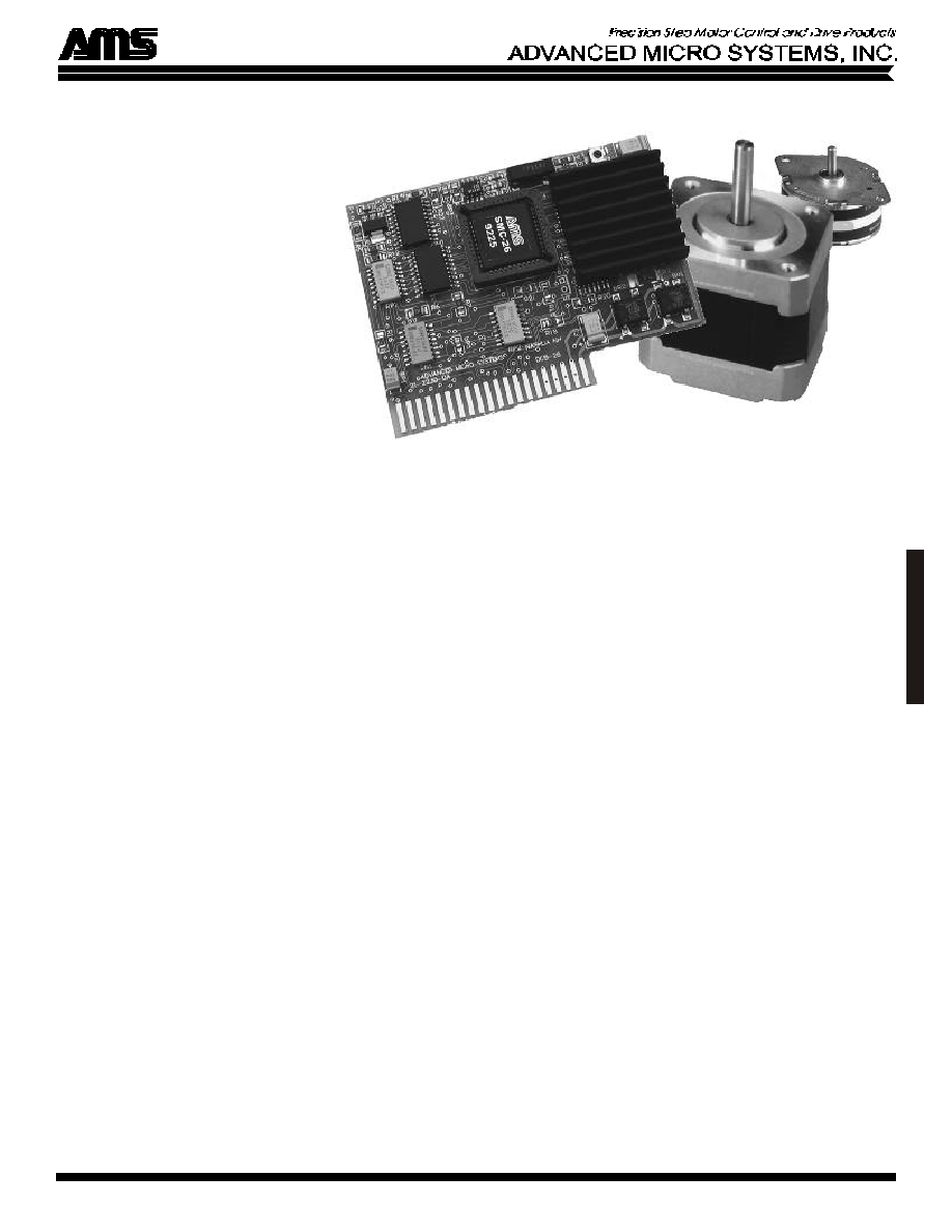
The CCB-26 is a low cost driver and
smart controller board suitable for
operating small stepper motors. It utilizes
bipolar power drivers with adjustable
currents of up to 0.85 amps (1.25 amps
with cooling) per phase. This all-in-one
package is designed for OEM applica-
tions using high volume production
linear actuators and rotary steppers. Built
in phase step sequences include 1/8, 1/4,
1/2, Full, and Wave drives.
The CCB-26 has an instruction set of
over 30 commands that include loop on
port, count delays, and set/clear ports. In
addition to 5 general-purpose ports, jog,
limit and home sensor inputs are also
available.
Other features include auxiliary step
pulse and direction inputs to allow
motion generation via external pulse
sources, with limit switch protection and
position counter tracking.
Application development is facilitated
with AMS' free software; featuring:
∑ Program Editor
∑ Syntax Checker Loader
∑ Microsoft "C" Source Code
∑ Pull-Down Menus
∑ Dumb Terminal Emulation
∑ Quick Basic Information Program
∑ Speed, Distance, Accel/Decel Plots
For evaluation and medium volume
production, a companion "mini-mother"
board simplifies product interface. The
dual axis board has an RS-232 interface,
expandable for multiple axes. The
communication, power and I.O. signal
connectors provide for real-world
interface.
PARTY LINE MODE
"Party Line" communication protocol
can be used in applications using a host
computer. This protocol greatly reduces
communication time and supports
between 1 and 60 axes of motion
connected in parallel from a single serial
port.
NON-VOLATILE MEMORY
2k bytes of non-volatile memory is
available to store user programs for
future execution. Any number of
programs may coexist, limited only by
the available memory space. Utilizing
this feature allows all parameters, such as
initial velocity, ramp and step mode to be
set as defaults then modified "on the fly"
during program execution.
TRIP POINT
The trip point is a programmable
position that allows predefined opera-
tions to be triggered when the motor
position matches the established trip
point position. During motion the
position counter is continuously updated
and compared to the programmed trip
position.
RESET
Upon hardware reset all parameters (set
by commands B,D,E,H,I,K,T,V) most
recently saved are downloaded into the
working registers of the controller. Both
Jog and Go inputs are then active.
During reset all outputs are off.
FEATURES
∑ Small in size
∑ 0.85 amp bipolar chopper drive
∑ Microstep to 1/8, 1/4, 1/2, Full step
∑ High torque full step mode
∑ Bi-directional ramping between speeds
∑ User I.O. ports
∑ Speeds to 25,000 steps per second
∑ Speed alterable "on the fly"
∑ Soft decelerate stop command & input
∑ Motion output signal
∑ Receive/send commands while moving
∑ Step register of over 16M steps
∑ Enable signal polarity (programmable)
∑ Special "Home" function at any step rate
∑ Read position counter while moving
∑ Limit and home switch inputs
∑ 2k non-volatile memory
∑ 9.6k / 470k Baud
∑ Programmable trip point
∑ Selectable "Party Line" serial mode
∑ Limit switch polarity (programmable)
∑ 16 way branch (on ports 1-3)
TERMINAL INTERFACE
By using a simple RS-232 buffer, motion
sequences can be programmed from a
standard terminal or host PC. Command
lines consist of an ASCII character
followed by a number. The input line
editor provides a user-friendly interface.
CCB-26
MICROSTEP DRIVER
WITH
INTELLIGENT
CONTROLLER
C
C
B
-
2
6
ADVANCED MICRO SYSTEMS, INC. reserves the right to make improvements and changes in specifications or prices at any time without prior notification. 9356
SUMMARY OF COMMANDS
ASCII Description
ESC
Abort/Terminate
A
Port Set/Increment/Read
B
Jog Speed/30: Slow, Fast
C
Restore, Clear Page
D
Divide Factor
E
Enable, Limit Sense
F
Find Home: Sense Speed
G
Go (Address/Branch), Trace
H
Select phase table
I
Initial Velocity-SPS
J
Jump To Address, Repetition
K
Ramp Slope
k
Trip Output Values
L
Loop On Port Condition
M
Constant Velocity-SPS
O
Set Origin
P
Program Mode
Q
Query Program
R
Relative Move
S
Store Parameters
T
Set Trip Point
V
Slew Velocity-SPS
W
Wait n Milliseconds
X
Examine Settings
Z
Read Position Once/Repeat
+
+ Step Command
-
- Step Command
\
Write To NV Memory
[
Read NV Memory
]
Query Hardware Status
^
Query Motion Status
@
Soft Stop
PROGRAMMABLE PHASE SEQUENCE
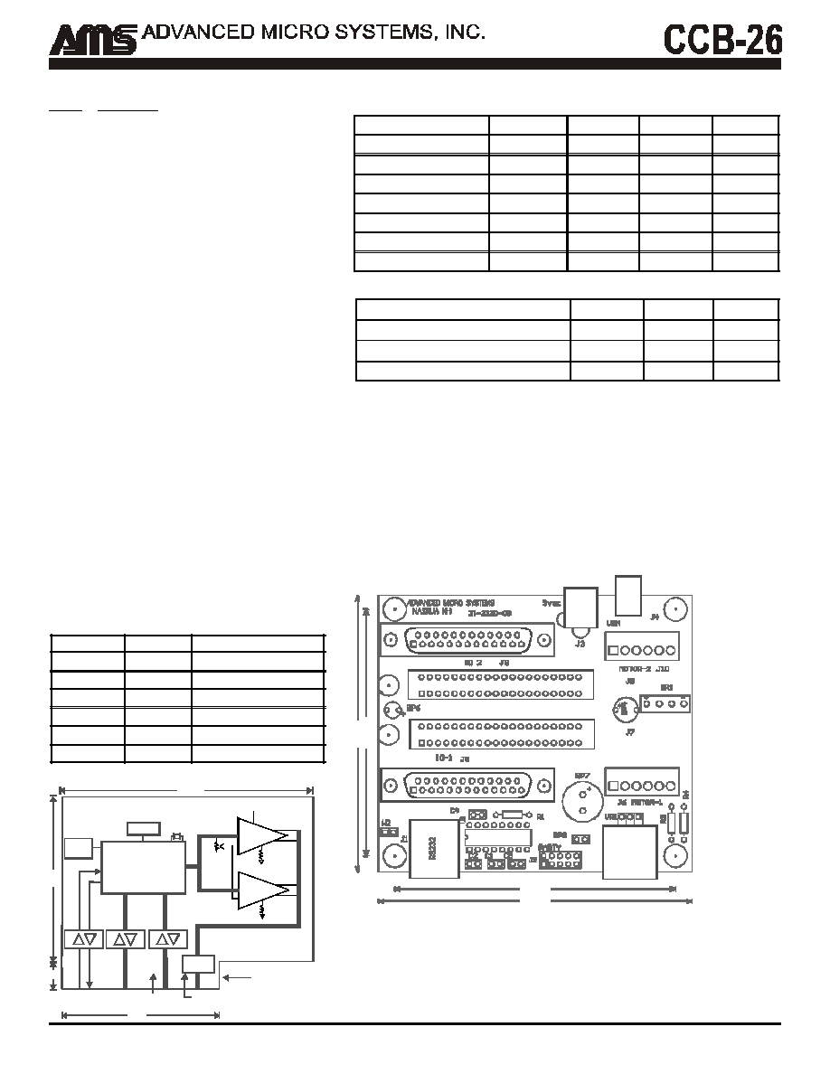
CCB-26 BLOCK DIAGRAM
ELECTRICAL SPECIFICATIONS
Logic D.C. Characteristics: (Vcc= 5V ±10%)
Drive Outputs @ 25 degrees C (Ambient)
2 AXIS MOTHER BOARD (MODEL DCMB)
The DCMB is an accessory to the CCB-26. It contains the interface for one or
two axis of motion control. The expansion connector provides the ability to
add more axis in a microprocessor based system.
∑ Two axis interface
∑ Expansion connector for multi-axis
∑ 1 amp, 5 volt regulator for additional load
∑ DB25 connector for input/output signals
∑ DC or 9-18 VAC input for low cost power
∑ Separate motor and power supply inputs
∑ RJ45 connector for RS-232 input
An RS-232 input converts standard serial voltages to TTL levels to drive up to 10
axis using Advanced Micro System's "Party Line" protocol. The open drain TXD
outputs from each axis are wire-or'd, providing a party line communication
method. Prior to operation each axis must be assigned a one character name that
is stored in the CCB-26 NV memory. Removing the "Party Line" jumper and
inserting one axis at a time facilitates name assignment.
2 Townsend West, Nashua, NH 03063-1277 603-882-1447 FAX 603-881-7600
Vmm
P1
CLAMP
CONTROL
ENABLE
5V SERIAL
VMM*
(POWER)
MOTOR
3.375
2.09
I/O
5V
POWER
RESET
NV MEM
SMC-26
5V/40ma
2
.
2
0
.
3
8
C U R R E N T
SENSE
DRIVER A
DRIVER B
3.40
3.80
3
.
0
0
3
.
3
7
Sequence
Steps/Rev Remark
1/8 Micro
1600
High resolution
1/4 Micro
800
Reduced resonance
1/2 Micro
400
Good speed
Full - Wave
200
One phase on
Half
400
High torque
Full
200
Highest torque
Description
Condition
Typ
Max
Unit
Icc: Supply current
Enabled
104
120
Ma
Icc: Supply current
Disabled
45
60.0
Ma
Vil: Input low voltage
-.05
0.85
Volts
IiI: Input low current
Vil=0.45V
-500.0
µa
Vih: Input high voltage
2.0
Vcc+0.55
Volts
Vol: Output low voltage
IoI=1.6ma
0.45
Volts
Voh: Output high voltage Ioh= -80µa
2.4
Volts
Description
Min
Max
Unit
Current per phase
0
0.85
Amps
Current per phase with cooling
1.25
Amps
Motor power supply (Vmm):
5
50
Volts