 | –≠–ª–µ–∫—Ç—Ä–æ–Ω–Ω—ã–π –∫–æ–º–ø–æ–Ω–µ–Ω—Ç: AS8412 | –°–∫–∞—á–∞—Ç—å:  PDF PDF  ZIP ZIP |

AS8412
HIGH PERFORMANCE
AUTOMOTIVE SONAR INTRUSION
Data Sheet
March 2001

High Performance Automotive Sonar Intrusion ≠ Data Sheet
AS8412
March 2001
Page 2 of 14
Key Features
∑
True sonar/pulse-echo operation
∑
Wide dynamic range
∑
Programmable sensitivity levels
∑
Self-adaptive to vehicle interiors
∑
Self-adaptive to temperature and environmental changes
∑
High sensitivity to intrusion
∑
Immunity to false alarms
∑
Detection of sabotage attempts
∑
Compatible with standard 40 kHz ultrasonic transducers
∑
No adjustments needed at factory or at field
∑
Few external components
∑
Time reference: external clock or oscillator based on crystal/ceramic resonator
∑
Built-in self-test
∑
Internal power-on-reset
∑
Advanced CMOS technology
∑
Low power consumption: 0.65 to 1.0 mA
∑
Operation between -40∞C and +85 ∞C
∑
Available in 20-pin DIP and 20-pin SOIC package
General Description
The AS8412 is a signal processing IC designed to implement reliable, high-performance
sonar intrusion detectors. It generates short 40 kHz bursts to feed an ultrasonic trans-
ducer. The resulting sonar waves are reflected on the vehicle interior and the echoes are
received by another transducer. Inside the AS8412, the electrical signal is first submitted
to an analog conditioning circuit, then it is digitized and processed by a DSP, whose out-
put is analyzed by a discriminator based on fuzzy-logic techniques. Thus, true intrusion
conditions can be discerned from natural phenomena and other allowable disturbances.
No adjustments are necessary at factory or at the field, as the AS8412 is self-adaptive to
the physical and environmental conditions. Compact and EMI-resistant intrusion detec-
tors are made possible, due to the small number of components.
Block Diagram
PRE-
AMP
BAND-PASS
FILTER
AGC
ENVELOPE
DETECTOR
A / D
CONVERTER
D S P
DISCRIMINATOR
MODULATOR /
DRIVER
CONTROL
LOGIC
OSCILLATOR
SIGNALLING
VCAP
SAS
SENS 1
SENS 0
ALEN
LED
WARN
ALARM
SEL40K
OSCIN
OSCOUT
TX1
TX2
RX

High Performance Automotive Sonar Intrusion ≠ Data Sheet
AS8412
March 2001
Page 3 of 14
Pin Description
AS8412
Pin #
Name
Description
1
TX1
40-kHz burst generator - output 1.
2
OSCIN
Clock input or crystal / ceramic resonator connection.
3
OSCOUT
Crystal / ceramic resonator connection. Not connected when external clock is applied.
4
VCAP
Pin for programming capacitor at the envelope detector.
5
AVDD
Analog supply voltage (+5V).
6
AGND
Analog ground.
7
RXGND
Analog ground.
8
RX
Ultrasonic echo input.
9
SEL40K
Time reference select input (SEL40K='1' to select 40 kHz or SEL 40K='0' to select 400 kHz
at OSCIN).
10
ALEN
Alarm enable input (when ALEN ='0', the outputs ALARM, WARN and LED are disabled).
11
SENS0
Sensitivity selection (least significant bit).
12
SENS1
Sensitivity selection (most significant bit).
13
SAS
SAS enable input (SAS='1' activates Self-Adjusting Sensitivity, SAS='0' keeps sensitivity
fixed)
14
TP
Test / reset pin. A rising edge resets the IC. This pin should be left unconnected or tied to
VDD for normal operation.
15
VDD
Digital supply voltage (+5V).
16
GND
Digital ground
17
LED
Active-low signalling LED output (open drain).
18
WARN
Active-low auxiliary alarm output (open drain).
19
ALARM
Active-low main alarm output (open drain).
20
TX2
40-kHz burst generator - output 2.
Pinout & Packaging
Available Package(s):
∑
20 pin DIP
∑
20 pin SOIC
TX1
OSCIN
OSCOUT
VCAP
AVDD
AGND
RXGND
RX
SEL40K
ALEN
TX2
ALARM
WARN
LED
GND
VDD
TP
SAS
SENS1
SENS0
1
2
3
4
5
6
7
8
9
10
20
19
18
17
16
15
14
13
12
11

High Performance Automotive Sonar Intrusion ≠ Data Sheet
AS8412
March 2001
Page 4 of 14
Absolute Maximum Ratings
Conditions: 1. AII voltages referenced to GND
2. AVDD connected to VDD
3. AGND connected to GND
Supply Voltage
< 7V
Input Pin Voltage
-0,3 V to VDD + 0.3 V
Output Pin Voltage
-0,3 V to VDD + 0.3 V
Power dissipation
500 mW
Operating temperature under bias
-40 ∞C to +85 ∞C
Storage Temperature
-65 ∞C to +150 ∞C
Latch-up immunity
-10mA ... + 10mA
Note:
Stresses above these values may cause permanent damage to the device.
Functional operational at these values is not implied
ESD immunity / HBM: 1500 Ohm; 100 pF
Recommended Operating Conditions
Parameter
Symbol
Min
Typ
Max
Units
Supply Voltage (VDD, AVDD)
V
DD
4.5
5.0
5.5
V
Operating Temperature Range
T
O
-40
-
85
∞C
Clock Frequency (SEL40K=1)
F
CK
39
40
41
kHz
AC Peak Voltage at RX Input
V
IN
0.1
-
10
mV
D.C. Electrical Characteristics
(V
DD
= 5 V, V
SS
= Ground, T
A
= -40 ∞C to +85 ∞C)
Parameter
Symbol
Min
Typ
Max
Units
Conditions
Low Level Input Voltage
V
il
-
-
1.5
V
Pins 2, 9, 11, 12, 13
High Level Input Voltage
V
ih
3.5
-
-
V
Pins 2, 9, 11, 12, 13
Low-to-High Threshold
V
t+
-
3.0
3.5
V
Pin 10 (Schmitt Trigger Input)
High-to-Low Threshold
V
t-
1.4
1.8
-
V
Pin 10 (Schmitt Trigger Input)
Hysteresis
V
h
0.6
-
-
V
Pin 10
Low Level Input Current
I
il
-1
-
-
µA
Pins 9, 10, 11, 12, 13, (V
DD
=5 V)
High Level Input Current
I
ih
-
-
1
µA
Pins 9, 10, 11, 12, 13, (V
DD
=5 V)
Input Resistance
R
in
-
200
-
k
Pin 8

High Performance Automotive Sonar Intrusion ≠ Data Sheet
AS8412
March 2001
Page 5 of 14
Low Level Output Voltage
Vol
-
-
-
0.5
0.5
0.5
V
V
V
Pins 1, 20
Pins 18, 19
Pins 17
Iol=3 mA
Iol=4 mA
Iol=12mA
High Level Output Voltage
Voh
4.0
-
-
V
Pins 1, 20
Ioh=-3 mA
High-Z Output Current
Ioz
-
-
10
µA
Pins 17, 18,
19
Vo=5V
Total Supply Current
Idd
-
-
0.65
1.0
1.0
1.6
mA
mA
SEL40K= 1
SEL40K= 0
crystal or clock
ceramic resonator
C1=C2=100pF
A.C. Electrical Characteristics
(V
DD
= 5 V, V
SS
= Ground, T
A
= 25∞C)
Parameter
Symbol
Min
Typ
Max
Units
Conditions
Power-on-reset width
t
por
50
500
500
-
-
-
70
530
800
ms
SEL40K= 0, resonator / clock
SEL40K= 1, clock
SEL40K= 1, crystal
Self-test delay (incl. t
por
)
t
std
1.3
1.7
1.7
-
-
-
1.4
1.9
2.1
s
SEL40K= 0, resonator / clock
SEL40K= 1, clock
SEL40K= 1, crystal
Fault indication pulse width
t
stw
4.3
-
4.6
s
ALARM low pulse width
t
al
200
-
-
ms
Pins 18, 19
LED low pulse width
t
onn
-
-
89
977
-
-
ms
ms
narrow = no detection
wide = detection
LED high pulse width
t
off
-
888
-
ms
System Description
Ultrasonic intrusion detectors are very popular in vehicle security systems, due to their low
cost, good area coverage and easiness of installation. The AS8412 uses the sonar principle to
build a high-performance intrusion detector that follows the requirements of the OEM automo-
tive industry. As very short ultrasonic bursts are sent, the power needed to drive the transmitter
is reduced. Interference and signal cancellation effects, present in systems with continuous
transmission, are virtually eliminated.
Fig. 1 shows the pulse/echo timing generated by the AS8412.
The basic concept behind the AS8412 is the detection of changes in the relative position of
objects inside the vehicle, by monitoring successive echo patterns with a discriminator based
on fuzzy-logic.
Despite the higher complexity of this approach, that demands both analog and digital signal
processing, the solution is made cost-effective with the use of a single IC and a small number
of external components.

High Performance Automotive Sonar Intrusion ≠ Data Sheet
AS8412
March 2001
Page 6 of 14
TX pulse
Echo in RX
44,4ms
0,6ms
Fig. 1 - Pulse/Echo Timing
Supply / Power-On Reset
The AS8412 requires a single 5-volt power supply. Pins for VDD and GND are separated for
the analog and digital circuits, and a 100 nF ceramic decoupling capacitor is recommended for
each pair.
There is an internal power-on-reset circuit that initializes the IC after each power-up. The VDD
rise time must be less than 20 ms, to guarantee proper initialization. Optionally, the IC can also
be reinitialized with a rising-edge at the pin 14, if requested by the application.
Time Reference
A clock must be present at the OSCIN input. The frequency may be selected to be either 40
kHz or 400 kHz, by setting the SEL40K input to `1' or `0' respectively. For the 40 kHz clock a
duty-cycle of approximately 50% is necessary.
The clock signal can be created in several possible ways:
∑
Generation by a microprocessor or other external circuit
∑
Built-in oscillator with an external 40-kHz crystal between OSCIN and OSCOUT. Depending
on the crystal, a load capacitor (about 22 pF) may be needed at OSCOUT.
∑
Built-in oscillator with an external 400-kHz ceramic resonator between OSCIN and
OSCOUT.
Load capacitors of at least 100 pF are necessary at the pins, according to the resonator speci-
fications. The IC power consumption increases with higher capacitor values (I
dd
= 1.0 mA with
100 pF capacitors).
Ultrasonic Transducers
The AS8412 is compatible with standard 40 kHz ultrasonic transducers, available from several
manufacturers. For each IC, one transducer is used to transmit the sonar pulses and one other
to receive the echoes reflected inside the vehicle. Internal lengths up to 3.5 meters can be cov-
ered.
In most applications, just two pairs of sensors will be used. The sensors will typically be posi-
tioned at the B-pillars (central pillars), close to the roof, to provide the best possible coverage of

High Performance Automotive Sonar Intrusion ≠ Data Sheet
AS8412
March 2001
Page 7 of 14
all the vehicle interior. Each pillar may have either a transmitter/receiver pair or two sensors of
the same kind. The first arrangement is recommended, as it allows a single box at each pillar
containing the AS8412 and the transducer pair controlled by it, thus decreasing cabling.
The outputs TX1 and TX2 drive the transmitter in a push-pull configuration with 10 V peak-to-
peak. As shown in Fig. 1, the transmission duty-cycle is very short (around 1/75), reducing the
average current needed to generate the ultrasonic bursts to about 0.05 mA per IC.
Shielded cable is mandatory for the receiver and recommended for the transmitter, unless they
are adjacent to the IC. The shield at the receiver cable must be grounded and connected to the
RXGND pin.
Analog Conditioning
The analog front-end, composed of a preamplifier and a filter centered at 40 kHz, increases the
signal level and removes noise outside the bandpass. It is followed by a digitally controlled AGC
amplifier, which keeps signal level at the VCAP output within prescribed levels. Finally, an en-
velope detector extracts the information embedded in the amplified echo signal.
The front-end needs proper bias during power-up. That can be provided by an RC series circuit
to VDD, as shown at Fig. 2, or alternatively, by the pre-amplifier of Fig. 4.
VDD
100n
100k
To RX-Pin
Fig. 2 - Series-RC circuit at RX
The AS8412 has a wide dynamic range, to follow the signal fluctuations that occur in a large
variety of vehicles, sensors and environmental conditions. Only under extreme conditions, like
in a larger vehicle, an external pre-amplifier at RX may help to improve performance.
A practical way to verify if a pre-amplifier might be useful, is by monitoring the echo waveform
at VCAP. A FET-input buffer (input impedance at least 10
9
ohm) should be used, as the output
impedance at VCAP is very high.
0
10
20
30
40
T(ms)
Period = 44,4 ms
VCAP(V)
3,0V-4,2V
1,3V-1,8V
Fig. 3 - Waveform at VCAP
High Performance Automotive Sonar Intrusion ≠ Data Sheet
AS8412
March 2001
Page 8 of 14
As a general rule, the best approach is to measure the voltage at the "valley", that normally
occurs at the end of the echo waveform. If it is above 1.8 V, then the system could benefit from
some extra gain.
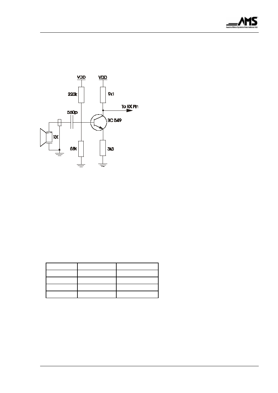
A pre-amplifier that satisfies the bias requirements is shown at the Fig. 4. Its gain is around
8 dB.
Fig. 4 - Recommended pre-amplifier
Sensitivity Programming
The AS8412 allows the sensitivity to intrusions and movements to be programmed at produc-
tion, so the manufacturer can adapt the detector to different requirements.
There are two possible ways of programming the sensitivity:
∑
Digital programming by the pins SENS1 and SENS0: controls the criteria used by the dis-
criminator to validate intrusions or movements. Four sensitivities are available, as shown at
Table 1.
Table 1. Digital programmable sensitivities
SENS1
SENS0
Sensitivity
1
1
High
1
0
Mid-high
0
1
Mid-low
0
0
Low
∑
Capacitor at the pin VCAP: controls the analog processing of the echo signal at the enve-
lope detector. With smaller capacitors, the digitized echo signal will have a higher resolution
and, as a result, a higher sensitivity will be obtained.
The best combination of digital programming and VCAP capacitor is usually determined by
experiment. A generally good choice is to use sensitivity mid-high and 270-pF capacitor at
VCAP.

High Performance Automotive Sonar Intrusion ≠ Data Sheet
AS8412
March 2001
Page 9 of 14
Table 2 shows some possible sensitivity combinations, marked according to the expected be-
havior at the field. It should be used as a guide to determine the best combination for each ap-
plication.
Table 2. Sensitivity as Function of Digital and VCAP Programming
PROGRAM
390 pF
330 pF
270 pF
220 pF
High
OK
OK
+
+
Mid-high
-
OK
OK
+
Mid-low
-
-
OK
OK
Low
-
-
-
OK
(+) positions with higher sensitivities; may present false alarms under extreme conditions
(OK) most usual sensitivity combinations
(-) positions with lower sensitivities; may be useful for specific applications
The Self-Adjusting Sensitivity (SAS)
The SAS (Self-Adjusting Sensitivity) control loop is a powerful feature that optimizes the sensi-
tivity to intrusion and motion, based on the present environmental conditions. Under quiet situa-
tions the detector has a very high sensitivity. On the other hand, when certain disturbances
such as thermal gradients appear inside the vehicle, the sensitivity is decreased to avoid pos-
sible false alarms.
The sensitivity range programmed by the manufacturer is not changed by the SAS, that simply
selects the most adequate sensitivity for each situation within the allowed range. Fig. 5 gives a
rough idea of how the SAS can affect the detector sensitivity, for a given capacitor at VCAP.
H I G H
L O W
M I D - L O W
M I D - H I G H
S E N S I T I V I T Y
Fig. 5 - Sensitivity Ranges with SAS
The SAS actuation is controlled by the SAS input.
∑
SAS enabled (pin SAS = "1"):
After power-on, the IC starts with the lowest sensitivity within the programmed range. The
sensitivity will be constantly adjusted, according to the external conditions. Even under quiet
conditions, the IC may take at least 2 minutes to reach the maximum allowed sensitivity.
That should be considered during system evaluation.

High Performance Automotive Sonar Intrusion ≠ Data Sheet
AS8412
March 2001
Page 10 of 14
∑
SAS disabled (pin SAS = "0")
The IC will keep the sensitivity fixed at the upper limit of the programmed range, regardless
of the environmental conditions. This mode can be useful in special applications that de-
mand a fixed or externally controlled sensitivity. The VCAP capacitor may have to be up to 4
times
bigger than it would be with the SAS enabled, to compensate the fixed high sensitivity and
avoid false alarms. Another use of this mode is to allow an easier characterization of the
upper sensitivity limit during the system development.
The self-test indicates an error with SAS="0". To generate a valid self-test, SAS must be `I'
during power-up. It may be switched afterwards.
Together with the AGC, the SAS loop provides improved controllability over the intrusion detec-
tion process, allowing the system to be little affected by changes in the external conditions,
such as temperature, supply voltage and sensitivity of the ultrasonic sensors.
In any case, the sensitivity can be very significant, so the AS8412 is not adequate to be used in
convertibles or with open windows.
DSP and Fuzzy-Logic Discriminator
Many external phenomena may affect the ultrasonic waves inside the vehicle. Sunlight, blows
at the glasses or roof, wind through the ventilation flaps are some examples.
Experiments have shown that a real intrusion can not be validated by a single specific charac-
teristic of the echo waveform. Several parameters must be observed at the same time and
also how they correlate with each other. Experimental data gathered from extensive field test-
ing were used to support the detection criteria embedded in the AS8412.
To implement those criteria, first the digitized echoes are processed by a DSP circuit to en-
hance the parameters to be monitored. Then, a fuzzy-logic discriminator continuously exam-
ines how those parameters change and correlate, to verify any possible intrusion.
Built-In-Self-Test
When power is applied and SAS = "1", the AS8412 goes automatically into a self-test routine
that checks the IC operation. It can also detect initialization errors due to a slow supply rise
time or a clock problem at OSCIN.
During the self-test period, the IC outputs are exercised and should be ignored. If the test is
successful, normal operation starts, indicated by the output LED pulsing periodically.
In the case of an IC malfunction, immediately after the self-test the LED and WARN outputs are
turned on (low) for about 4.4 seconds. If a light-emitting diode is connected to the LED output,
the self-test message may be seen directly by the user.
After an error message, the LED starts to blink again, as in a normal operation. Fig. 6 shows
the possible self-test waveforms after power-on.

High Performance Automotive Sonar Intrusion ≠ Data Sheet
AS8412
March 2001
Page 11 of 14
VDD
WARN
DON'T CARE
DON'T CARE
t
std
t
off
t
onn
VDD
WARN
DON'T CARE
DON'T CARE
t
onn
t
off
t
std
( a )
( b )
stw
t
Fig. 6
(a) Self-Test OK
(b) Error at Self-Test
Alarm Signalling
The AS8412 can indicate not only intrusion or motion, but also other kinds of disturbance, and
send a particular message for each situation. Those disturbances are defined as follows and
the messages are identified at Table 3.
∑
Weak intrusion: early stages of an intrusion, or a weaker intrusion or movement. Detection
criteria are similar to those for intrusion, but with higher sensitivity.
∑
Blockage: elimination of the coupling between the transducers, either by blocking one of
them, or by cutting a wire.
∑
Saturation: very strong 40-kHz signal at RX, possibly an attempt to sabotage the alarm
system by saturating the receiver. May also be caused by a glass breakage or by strong hits
with hard objects at the glass.
With this signalling scheme, the IC has flexibility to be used either in simpler applications or in
sophisticated microprocessor based systems. In addition, the manufacturer has the option to
choose which kind of disturbance should be an alarm condition.
The pulse widths are those specified in the AC electrical Characteristics and shown in Fig. 7.
At ALARM and WARN they are at least 200ms; the outputs remain active if intrusion or motion
persists.
The WARN output could be used instead of the ALARM, if only intrusion detections should be
flagged. In this case, the digital sensitivity should be scaled one step ower (for instance from
mid-high to mid-low), or the capacitor at VCAP increased, to keep approximately the same
sensitivity.

High Performance Automotive Sonar Intrusion ≠ Data Sheet
AS8412
March 2001
Page 12 of 14
The blockage and saturation are signalized just one time at each occurrence, to avoid continu-
ous alarm triggering. Detection of glass breakage by saturation is not guaranteed.
Table 3. Disturbances detected by the AS8412
LED
ALARM
WARN
Conditions
pulsing
1
1
no disturbance
pulsing
1
0
weak intrusion
0
0
0
intrusion
pulsing
0
1
blockage
0
0
1
saturation
WARN
ALARM
t
al
t
al
t
al
t
ONW
t
ONN
Fig. 7 - Weak Intrusion followed by an Intrusion
Courtesy Entry/Exit Time
The pin ALEN is an optional alarm enable input that can be used to provide a courtesy entry
and/or exit time. When tied to VDD, normal alarm operation is enabled. If ALEN is grounded,
the outputs ALARM, WARN and LED are disabled, except during the self-test, when LED indi-
cates the test result.
By grounding ALEN, the IC can be made inoperative as seen by the control unit and still keeps
its internal processing. This is useful when intrusion detections must be temporarily inhibited,
or to block self-test pulses at ALARM and WARN.
During the first 10 or 20 seconds after shutting a door in a hot and sunny day, an alarm indica-
tion may occur, due to thermal gradients inside the vehicle. That should be considered when
choosing a courtesy time for an AS8412-based system. When an RC circuit connected to the
supply voltage is applied to ALEN, the courtesy time after power-up is given by:
T
0.92 x R x C

High Performance Automotive Sonar Intrusion ≠ Data Sheet
AS8412
March 2001
Page 13 of 14
Application Circuits
The AS8412 is designed to provide a flexible utilization, so many application circuits are possi-
ble. Only two of them are presented.
The Application Circuit I of Fig. 8a is suitable to be used in a microcontroller-based alarm sys-
tem. The 40-kHz clock is synthesized by the microcontroller, that also controls the digital sen-
sitivity. By having access to all the signalling outputs, the alarm system can be programmed to
signalize any combination of the disturbances detectable by the AS8412.
This arrangement uses a minimum number of components to implement an intrusion detector.
TX1
OSCIN
OSCOUT
VCAP
AVDD
AGND
RXGND
RX
SEL4OK
ALEN
1
2
3
4
5
6
7
8
9
10
20
19
18
17
16
15
14
13
12
11
TX2
ALARM
WARN
LED
GND
VDD
TP
SAS
SENS1
SENS0
UT1
40kHz
from
µ-Processor
N.C.
C1
VDD
C2
100n
R1
100k
C4
100n
UT2
To
µ-Processor
Programmable
Sensitivity
(Digital)
SAS Control
N.C.
VDD
VDD
C3
100n
Fig. 8a - Application Circuit I
TX1
OSCIN
OSCOUT
VCAP
AVDD
AGND
RXGND
RX
SEL4OK
ALEN
1
2
3
4
5
6
7
8
9
10
20
19
18
17
16
15
14
13
12
11
TX2
ALARM
WARN
LED
GND
VDD
TP
SAS
SENS1
SENS0
R2
100k
C1
100p
UT2
VDD
Programmable
Sensitivity
(Digital)
N.C.
VDD
C5
100n
VDD
VDD
N.C.
C2
100p
C3
R3
C6
100n
C4
100n
UT1
CR1
R1
D1
To Control Unit
C7
Fig. 8b - Application Circuit II

High Performance Automotive Sonar Intrusion ≠ Data Sheet
AS8412
March 2001
Page 14 of 14
The Application Circuit II of Fig. 8b can be used in a simpler system, that does not need micro-
controller. A 400-kHz oscillator is built with a ceramic resonator. By using just the ALARM out-
put, the system is able to detect intrusion, blockage and saturation as alarm of the operation
and of the IC self-test diagnostic. A courtesy time is provided by R3 and C7.
EMI Protection
The usual precautions against EMI, such as PCB with ground plane, short tracks and shielded
cables, are recommended for AS8412 applications, to avoid possible effects from noise in-
duced by external sources.
The RX cable must be shielded, because of the low-voltage signal. An alternative to protect
other pins directly connected to unshielded cables, is to clamp induced voltages with signal
diodes close to the pins (Fig.9)
If a single shielded cable is used for the transmitting sensor, the internal wire may be con-
nected to TX1 and the shield connected to TX2. In this case, only the TX2 output will need pro-
tection diodes
IC
V D D
(a)
(b)
Fig. 9 - Diode Clamp Protection for
Unshielded Cables
(a) pins 1, 20
(b) pins 17, 18, 19
Copyright
©
2000, Austria Mikro Systeme International AG, Schloþ Premst‰tten, 8141 Unterpremst‰tten, Austria.
All rights reserved. No part of this publication may be reproduced, stored in a retrieval system, or transmitted, in any form or by
any means, without the prior permission in writing by the copyright holder. To the best of its knowledge, Austria Mikro Systeme
International asserts that the information contained in this publication is accurate and correct.
IC