 | –≠–ª–µ–∫—Ç—Ä–æ–Ω–Ω—ã–π –∫–æ–º–ø–æ–Ω–µ–Ω—Ç: AP1625W | –°–∫–∞—á–∞—Ç—å:  PDF PDF  ZIP ZIP |
AP1625
PWM/PFM Dual Mode Step-down DC/DC Controller
This datasheet contains new product information. Anachip Corp. reserves the rights to modify the product specification without notice. No liability is assumed as a result of the use of
this product. No rights under any patent accompany the sale of the product.
Rev.1.1 May.27, 2004
1/5
Features
- Input voltage range:2.2V~8VV
OUT
type
- Adjustable version±2.5%
- Oscillator frequency: 270KHz±15%
- High Efficiency: 92%typ .
- Stand-by capability: I
STB
3µA.max .
- Soft-start time set-up externally type possible
- Output voltage type possibleFB
- Package: SOT23-5
Applications
Electronic Information Organizers
Palmtops
Cellular and portable phones
Portable Audio Systems
Various Multi-function Power Supplies
General Descriptions
The AP1625 series are multi-functional step-down
DC/DC converters with built-in speed, low ON
resistance drivers. A more than 1A output current is
possible using an externally connected transistor,
coil, diode and capacitor.
Output voltage is set-up by external resistor.±2.5%
accuracy.
With a 270KHz switching frequency, the size of the
external components can be reduced.
Control switches from PWM to PFM during light
loads with the AP1625PWM/PFM switchableand
the series is highly efficient from light loads to large
output currents.
In relation to soft-start time external capacitor
regulated types.
During stand-by time CE pin "LOW",current
consumption is reduced to less than 0.5µA.
With U.V.L.O internal, the external MOSFET. Will
be forcibly switched off if used below the stipulated
voltage.
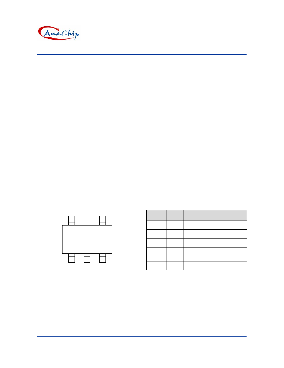
Pin Assignment
1
3
2
5
4
CE
V
OUT
V
DD
GND
SOT23-5
FB
(Top View)
Pin Descriptions
Pin No.
Pin
Name
Function
1 V
OUT
External PMOSFET Connection
2 V
DD
Power
Supply
3 GND Ground
4 CE
Chip Enable
Soft-start capacitor connection
5 FB
Feedback
pin
AP1625
PWM/PFM Dual Mode Step-down DC/DC Controller
Anachip Corp.
www.anachip.com.tw
Rev.1.1 May.27, 2004
2/5
Ordering Information
AP1625 X X X
W : SOT23-5
Packing
A : Taping
Package
Lead Free
Blank : Normal
L : Lead Free Package
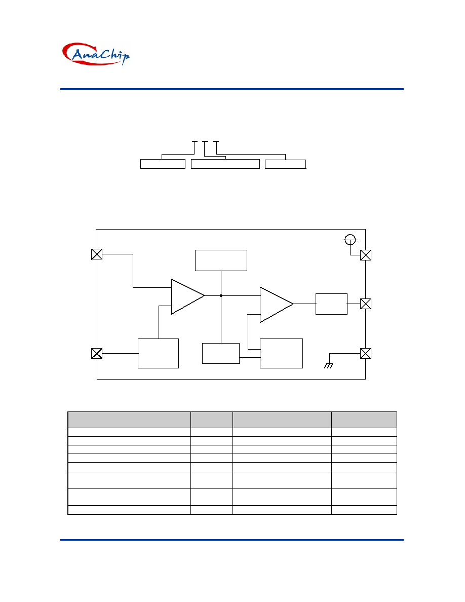
Block Diagrams
Phase
Compensation
Vref with
Soft Start
CE
+
-
PWM/PFM
Controller
+
-
Ramp Wave
Generator,
OSC
Buffer,
Driver
V
out
CE
GND
V
DD
PWM
Comparator
FB
Absolute Maximum Ratings
Ta=25∞C
Parameter
Symbol
Rating
Unit
V
IN
Pin Voltage
V
DD
-0.3
~
8.5
V
V
OUT
Pin Voltage
V
OUT
-0.3 ~ V
IN
+0.3 V
FB Pin Voltage
V
FB
-0.3 ~ V
IN
+0.3 V
CE Pin Voltage
V
CE
-0.3 ~ V
IN
+0.3 V
V
OUT
Pin Current
V
OUT
±
100
mA
Continuous Total
Power Dissipation
Pd 250
mW
Operating Ambient
Temperature
Topr -30
~
+80
∞C
Storage Temperature
Tstg
-40 ~ +125
∞C
AP1625
PWM/PFM Dual Mode Step-down DC/DC Controller
Anachip Corp.
www.anachip.com.tw
Rev.1.1 May.27, 2004
3/5
Electrical Characteristics
AP1625 V
OUT
3.3V, F
OSC
270KHz Ta=25∞C
Parameter
Symbol
Conditions
Min. Typ. Max.
Unit
FB V
FB
1.17
1.2
1.23
V
Maximum Input Voltage
V
IN
8
V
UVLO Voltagemin. operating
voltage
V
UVLO
Same as I
DD
, voltage required to
maintain H at V
OUT
2.2
V
Supply Current
I
DD
No external components,
CE=V
IN
,
V
OUT
=0V
40
110
µA
Stand-by Current
I
STB
No external components,
CE=V
IN
,
V
OUT
=0V
2 µA
Oscillator Frequency
Fosc
Measuring of EXT/waveform,
V
IN
=output voltage+0.3V
230 270 310
KHz
Maximum Duty Ratio
MAXDTY
100
%
PFM Duty Ratio
PFMDTY NO load (AP1625 only)
15
25
35
%
CE"High" Voltage
V
CEH
NO external components, V
FB
=0V,
apply 0.65V (min.) to CE,determine
V
OUT
"Low"
0.5 Vcc
CE"Low" Voltage
V
CEL
Same as V
CEH
, determine
EXT/"High"
0.20
V
Efficiency
EFFI
92 %
Soft-Start Time
Tss
Use a 33 nF Capacitor
5
15
msec
Measuring conditions: Unless otherwise specified, connect external components. V
IN
=5.0V,L
OUT
=220mA
Series Amendment:
AP1625
External Components: Css 0.033µF, Rss470k
The Following Parameter Applies:
Soft Start TimeTss:Connect Rss,CSS. CE,0V3.0VWhen V
IN
<3.0V, V
IN
3.0V
AP1625
PWM/PFM Dual Mode Step-down DC/DC Controller
Anachip Corp.
www.anachip.com.tw
Rev.1.1 May.27, 2004
4/5
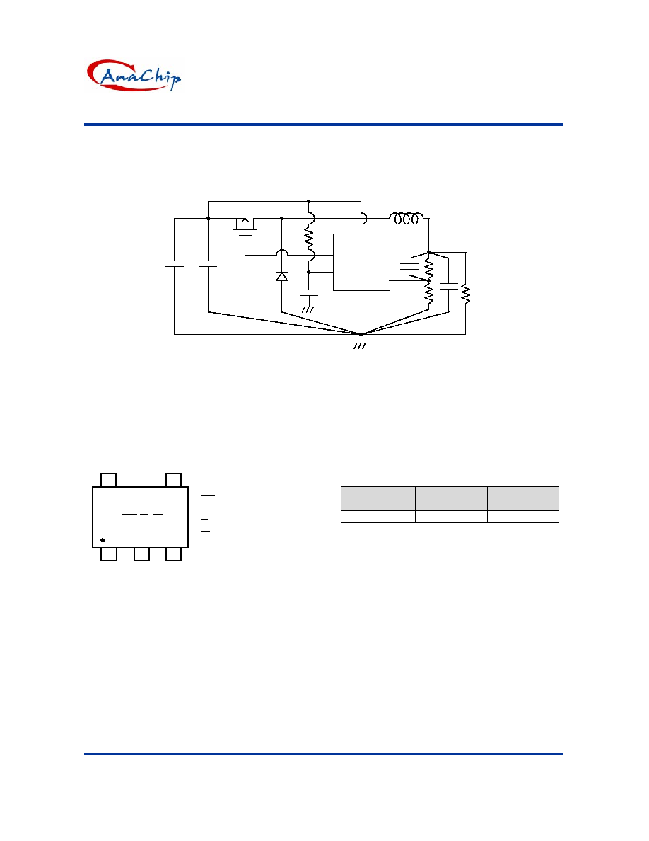
Typical Application Circuit
AP1625
V
DD
CE FB
GND
R
L
V
OUT
+C
L
L
SD
PMOS
V
IN
+C
IN
C
FB
R
FB1
R
FB2
V
OUT
R
SS
C
SS
Marking Information
SOT23-5L
XX : Identification code
(See Appendix)
Y : Year: 0-9
M : Month: A~L
X : Blank: normal
L: Lead Free Package
SOT23-5L
XX Y M X
7
1
2
3
4
5
Appendix
Part Number
Package
Identification
Code
AP1625 SOT23-5 EW
AP1625
PWM/PFM Dual Mode Step-down DC/DC Controller
Anachip Corp.
www.anachip.com.tw
Rev.1.1 May.27, 2004
5/5
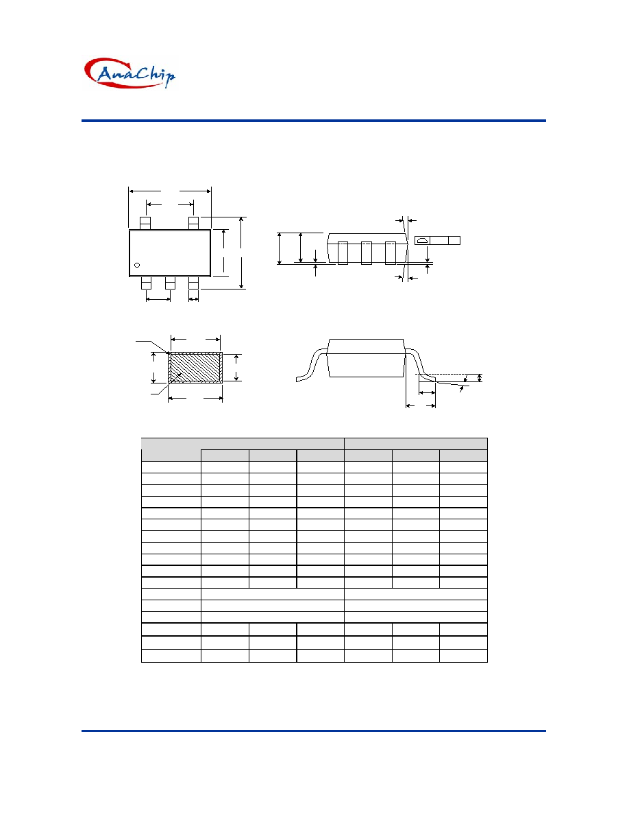
Package Information
Package Type: SOT23-5L
Gauge Plane
0.25 mm
L
L1
E1
E
e1
D
1
2
3
4
5
b
e
b1
b
C
C1
Base
Metal
With
Plating
A2
A1
A
Seating Plane
0.10 C
5x
2(4x)
1(4x)
Dimensions In Millimeters
Dimensions In Inches
Symbol
Min.
Nom.
Max.
Min.
Nom.
Max.
A
1.05 1.20 1.35 0.041 0.047 0.053
A1 0.05 0.10 0.15 0.002
0.004 0.006
A2 1.00 1.10 1.20 0.039 0.043 0.047
b 0.25 - 0.55
0.010 - 0.022
b1 0.25 0.40 0.45 0.010 0.016 0.018
c 0.08 - 0.20
0.003 - 0.008
c1 0.08
0.11
0.15
0.003
0.004
0.006
D
2.70 2.85 3.00 0.106
0.112
0.118
E
2.60 2.80 3.00 0.102 0.110 0.118
E1 1.50 1.60 1.70 0.059
0.063
0.067
L
0.35 0.45 0.55 0.014 0.018 0.022
L1 0.60
Ref.
0.024
Ref.
e
0.95 Bsc.
0.037 Bsc.
e1
1.90 Bsc.
0.075 Bsc.
0
o
5
o
10
o
0
o
5
o
10
o
1
3
o
5
o
7
o
3
o
5
o
7
o
2
6
o
8
o
10
o
6
o
8
o
10
o