 | –≠–ª–µ–∫—Ç—Ä–æ–Ω–Ω—ã–π –∫–æ–º–ø–æ–Ω–µ–Ω—Ç: AAT2556 | –°–∫–∞—á–∞—Ç—å:  PDF PDF  ZIP ZIP |
General Description
The AAT2556 is a member of AnalogicTech's Total
Power Management ICTM (TPMICTM) product fam-
ily. It is a fully integrated 500mA battery charger
plus a 250mA step-down converter. The input volt-
age range is 4V to 6.5V for the battery charger and
2.7V to 5.5V for the step-down converter, making it
ideal for single-cell lithium-ion/polymer battery-
powered applications.
The battery charger is a complete constant current/
constant voltage linear charger. It offers an inte-
grated pass device, reverse blocking protection,
high current accuracy and voltage regulation,
charge status, and charge termination. The charg-
ing current is programmable via external resistor
from 15mA to 500mA. In addition to standard fea-
tures, the device offers over-voltage, current limit,
and thermal protection.
The step-down converter is a highly integrated
converter operating at 1.5MHz of switching fre-
quency, minimizing the size of external compo-
nents while keeping switching losses low. It has
independent input and enable pins. The output
voltage ranges from 0.6V to the input voltage. The
feedback and control deliver excellent load regula-
tion and transient response with a small output
inductor and capacitor.
The AAT2556 is available in a Pb-free, thermally-
enhanced TDFN33-12 package and is rated over
the -40∞C to +85∞C temperature range.
Features
∑
Battery Charger:
-- Input Voltage Range: 4V to 6.5V
-- Programmable Charging Current up to
500mA
-- Highly Integrated Battery Charger
-- Charging Device
-- Reverse Blocking Diode
∑
Step-Down Converter:
-- Input Voltage Range: 2.7V to 5.5V
-- Output Voltage Range: 0.6V to V
IN
-- 250mA Output Current
-- Up to 96% Efficiency
-- 30µA Quiescent Current
-- 1.5MHz Switching Frequency
-- 100µs Start-Up Time
∑
Short-Circuit, Over-Temperature, and Current
Limit Protection
∑
TDFN33-12 Package
∑
-40∞C to +85∞C Temperature Range
Applications
∑
BluetoothTM Headsets
∑
Cellular Phones
∑
Handheld Instruments
∑
MP3 and Portable Music Players
∑
PDAs and Handheld Computers
∑
Portable Media Players
AAT2556
Battery Charger and Step-Down
Converter for Portable Applications
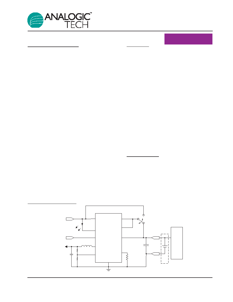
Typical Application
C
BATT -
ADP
ISET
GND
BAT
BATT +
Adapter / USB Input
STAT
EN_BAT
Enable
R
SET
VIN
EN_BUCK
L= 3.3µH
FB
LX
R
FB2
R
FB1
C
OUT
V
OUT
System
Battery Pack
2556.2006.05.1.0
1
SystemPower
TM
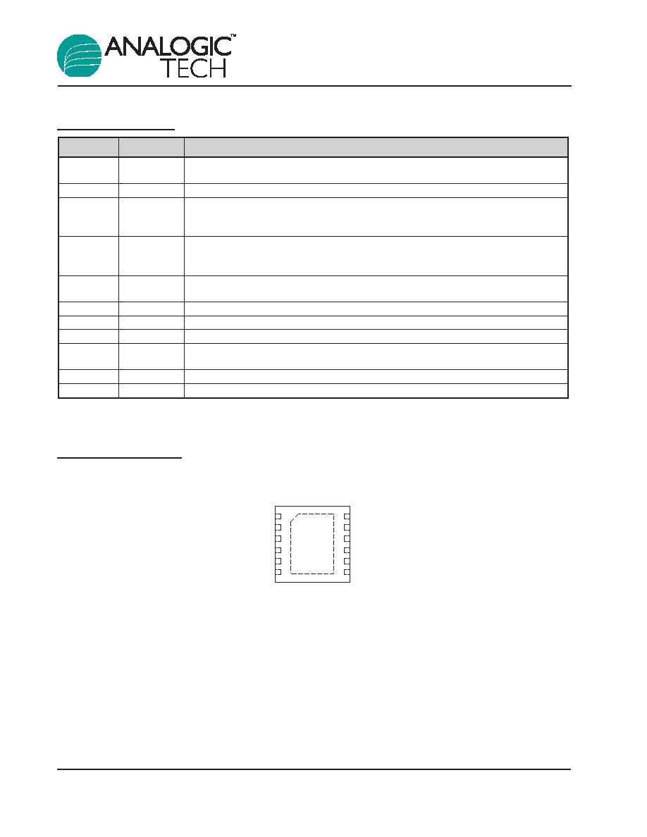
Pin Descriptions
Pin Configuration
TDFN33-12
(Top View)
FB
GND
EN_BUCK
1
EN_BAT
ISET
BAT
VIN
LX
GND
ADP
GND
STAT
2
3
4
5
6
12
11
10
9
8
7
Pin #
Symbol
Function
1
FB
Feedback input. This pin must be connected directly to an external resistor divider.
Nominal voltage is 0.6V.
2, 8, 10
GND
Ground.
3
EN_BUCK
Enable pin for the step-down converter. When connected to logic low, the step-down
converter is disabled and it consumes less than 1µA of current. When connected to
logic high, it resumes normal operation.
4
EN_BAT
Enable pin for the battery charger. When internally pulled down, the battery charger is
disabled and it consumes less than 1µA of current. When connected to logic high, it
resumes normal operation.
5
ISET
Charge current set point. Connect a resistor from this pin to ground. Refer to typical
curves for resistor selection.
6
BAT
Battery charging and sensing.
7
STAT
Charge status input. Open drain status input.
9
ADP
Input for USB/adapter charger.
11
LX
Output of the step-down converter. Connect the inductor to this pin. Internally, it is
connected to the drain of both high- and low-side MOSFETs.
12
VIN
Input voltage for the step-down converter.
EP
Exposed paddle (bottom): connect to ground directly beneath the package.
AAT2556
Battery Charger and Step-Down
Converter for Portable Applications
2
2556.2006.05.1.0
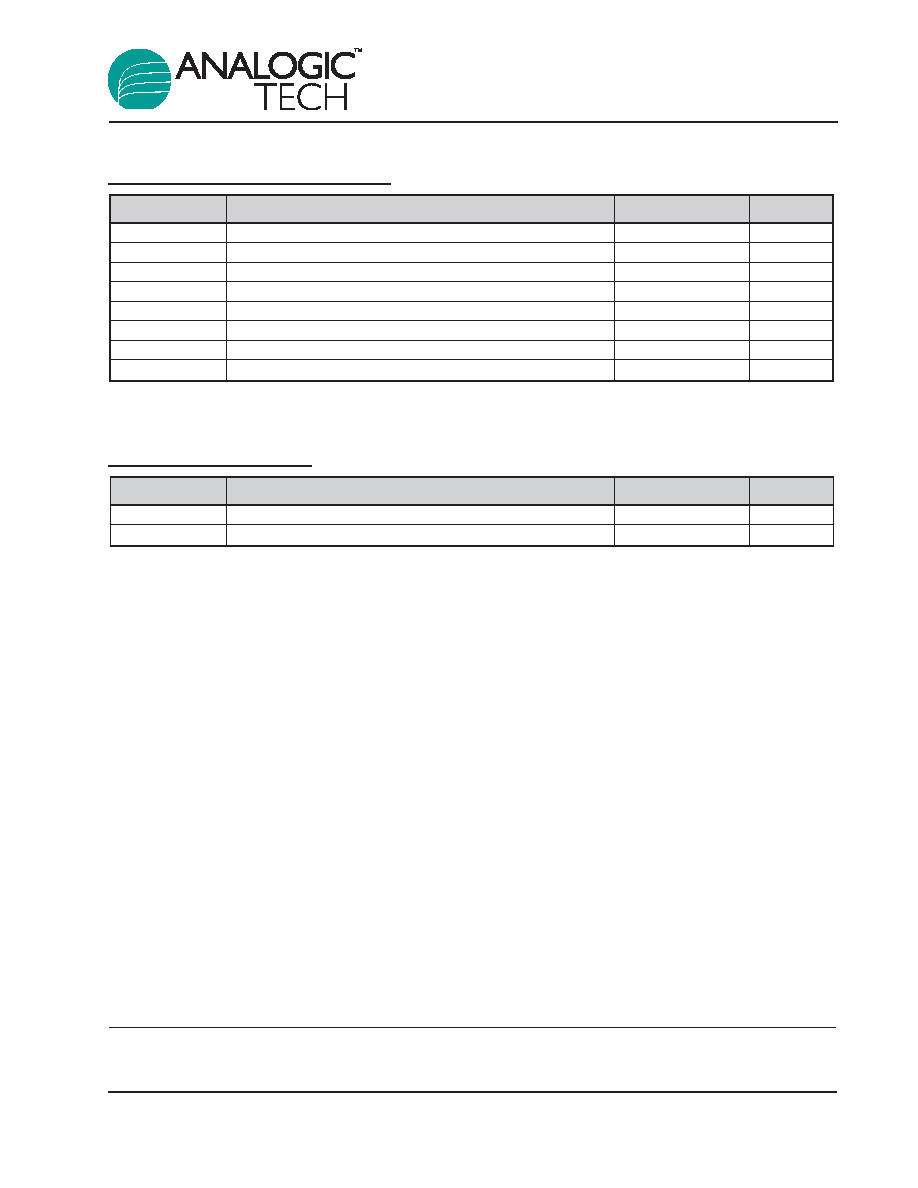
Absolute Maximum Ratings
1
Thermal Information
Symbol
Description
Value
Units
P
D
Maximum Power Dissipation
2.0
W
JA
Thermal Resistance
2
50
∞C/W
Symbol
Description
Value
Units
V
IN
Input Voltage to GND
6.0
V
V
ADP
Adapter Voltage to GND
-0.3 to 7.5
V
V
LX
LX to GND
-0.3 to V
IN
+ 0.3
V
V
FB
FB to GND
-0.3 to V
IN
+ 0.3
V
V
EN
EN_BAT and EN_BUCK to GND
-0.3 to 6.0
V
V
X
BAT, ISET and STAT to GND
-0.3 to V
ADP
+ 0.3
V
T
J
Operating Junction Temperature Range
-40 to 150
∞C
T
LEAD
Maximum Soldering Temperature (at leads, 10 sec)
300
∞C
AAT2556
Battery Charger and Step-Down
Converter for Portable Applications
2556.2006.05.1.0
3
1. Stresses above those listed in Absolute Maximum Ratings may cause permanent damage to the device. Functional operation at conditions
other than the operating conditions specified is not implied. Only one Absolute Maximum Rating should be applied at any one time.
2. Mounted on an FR4 board.
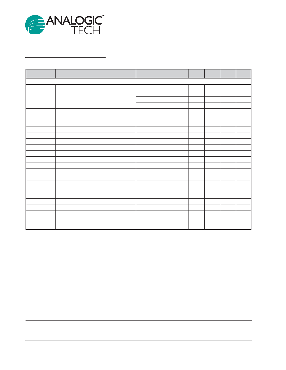
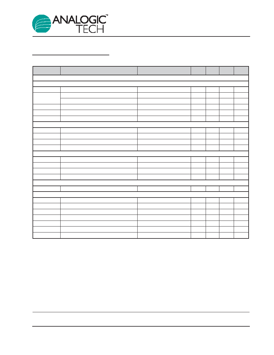
Electrical Characteristics
1
V
IN
= 3.6V; T
A
= -40∞C to +85∞C, unless otherwise noted. Typical values are T
A
= 25∞C.
Symbol
Description
Conditions
Min
Typ
Max Units
Step-Down Converter
V
IN
Input Voltage
2.7
5.5
V
V
IN
Rising
2.7
V
V
UVLO
UVLO Threshold
Hysteresis
200
mV
V
IN
Falling
1.8
V
V
OUT
Output Voltage Tolerance
2
I
OUT
= 0 to 250mA,
-3.0
3.0
%
V
IN
= 2.7V to 5.5V
V
OUT
Output Voltage Range
0.6
V
IN
V
I
Q
Quiescent Current
No Load
30
µA
I
SHDN
Shutdown Current
EN = GND
1.0
µA
I
LIM
P-Channel Current Limit
600
mA
R
DS(ON)H
High-Side Switch On Resistance
0.59
R
DS(ON)L
Low-Side Switch On Resistance
0.42
I
LXLEAK
LX Leakage Current
V
IN
= 5.5V, V
LX
= 0 to V
IN
1.0
µA
V
Linereg
/
V
IN
Line Regulation
V
IN
= 2.7V to 5.5V
0.2
%/V
V
FB
Feedback Threshold Voltage Accuracy
V
IN
= 3.6V
0.597
0.606
0.615
V
I
FB
FB Leakage Current
V
OUT
= 1.0V
0.2
µA
F
OSC
Oscillator Frequency
1.5
MHz
T
S
Startup Time
From Enable to Output
100
µs
Regulation
T
SD
Over-Temperature Shutdown Threshold
140
∞C
T
HYS
Over-Temperature Shutdown Hysteresis
15
∞C
V
EN(L)
Enable Threshold Low
0.6
V
V
EN(H)
Enable Threshold High
1.4
V
I
EN
Input Low Current
V
IN
= V
EN
= 5.5V
-1.0
1.0
µA
AAT2556
Battery Charger and Step-Down
Converter for Portable Applications
4
2556.2006.05.1.0
1. The AAT2556 is guaranteed to meet performance specifications over the -40∞C to +85∞C operating temperature range and is assured
by design, characterization, and correlation with statistical process controls.
2. Output voltage tolerance is independent of feedback resistor network accuracy.
Electrical Characteristics
1
V
ADP
= 5V; T
A
= -40∞C to +85∞C, unless otherwise noted. Typical values are T
A
= 25∞C.
Symbol
Description
Conditions
Min
Typ
Max Units
Battery Charger
Operation
V
ADP
Adapter Voltage Range
4.0
6.5
V
V
UVLO
Under-Voltage Lockout (UVLO)
Rising Edge
3
4
V
UVLO Hysteresis
150
mV
I
OP
Operating Current
Charge Current = 200mA
0.5
1
mA
I
SHUTDOWN
Shutdown Current
V
BAT
= 4.25V, EN = GND
0.3
1
µA
I
LEAKAGE
Reverse Leakage Current from BAT Pin
V
BAT
= 4V, ADP Pin Open
0.4
2
µA
Voltage Regulation
V
BAT_EOC
End of Charge Accuracy
4.158
4.20
4.242
V
V
CH
/V
CH
Output Charge Voltage Tolerance
0.5
%
V
MIN
Preconditioning Voltage Threshold
2.85
3.0
3.15
V
V
RCH
Battery Recharge Voltage Threshold
Measured from V
BAT_EOC
-0.1
V
Current Regulation
I
CH
Charge Current Programmable Range
15
500
mA
I
CH
/I
CH
Charge Current Regulation Tolerance
10
%
V
SET
ISET Pin Voltage
2
V
K
I_A
Current Set Factor: I
CH
/I
SET
800
Charging Devices
R
DS(ON)
Charging Transistor On Resistance
V
ADP
= 5.5V
0.9
1.1
Logic Control/Protection
V
EN(H)
Input High Threshold
1.6
V
V
EN(L)
Input Low Threshold
0.4
V
V
STAT
Output Low Voltage
STAT Pin Sinks 4mA
0.4
V
I
STAT
STAT Pin Current Sink Capability
8
mA
V
OVP
Over-Voltage Protection Threshold
4.4
V
I
TK
/I
CHG
Pre-Charge Current
I
CH
= 100mA
10
%
I
TERM
/I
CHG
Charge Termination Threshold Current
10
%
AAT2556
Battery Charger and Step-Down
Converter for Portable Applications
2556.2006.05.1.0
5
1. The AAT2556 output charge voltage is specified over the 0∞ to 70∞C ambient temperature range; operation over the -25∞C to +85∞C
temperature range is guaranteed by design.