
General Description
The AAT3685 BatteryManagerTM is a member of
AnalogicTech's Total Power Management ICTM
(TPMICTM) product family. This device is a highly
integrated single cell lithium-ion/polymer battery
charger IC designed to operate with USB port or
line adapter inputs. It requires the minimum number
of external components.
The AAT3685 precisely regulates battery charge volt-
age and current for 4.2V lithium-ion/polymer battery
cells. Regardless of the type of input power source
(USB or adapter), the AAT3685 can be programmed
for two separate constant current charge levels up to
1A. An optional Charge Reduction Loop is built in to
allow users to charge the battery with available cur-
rent from the charge supply, while keeping the port
voltage regulated.
Battery temperature and charge state are fully
monitored for fault conditions. In the event of an
over-voltage or over-temperature failure, the
device will automatically shut down, thus protecting
the charging device, control system, and the bat-
tery under charge. Status monitor output pins are
provided to indicate the battery charge status by
directly driving two external LEDs. A serial interface
output is available to report any one of 14 various
status states to a microcontroller.
The AAT3685 is available in a Pb-free, thermally-
enhanced, space-saving 12-pin 3x3mm TDFN
package and is rated over the -40∞C to +85∞C tem-
perature range.
Features
∑
Adapter or USB Charger
-- Programmable up to 1A Max
∑
4.0V to 5.5V Input Voltage Range
∑
High Level of Integration With Internal:
-- Charging Device
-- Reverse Blocking Diode
-- Current Sensing
∑
Automatic Recharge Sequencing
∑
Charge Reduction Loop
∑
Battery Temperature Monitoring
∑
Full Battery Charge Auto Turn-Off
∑
Over-Voltage Protection
∑
Emergency Thermal Protection
∑
Power On Reset and Soft Start
∑
Serial Interface Status Reporting
∑
12-Pin 3x3mm TDFN Package
Applications
∑
Cellular Telephones
∑
Digital Still Cameras
∑
Hand-Held PCs
∑
MP3 Players
∑
Personal Data Assistants (PDAs)
∑
Other Lithium-Ion/Polymer Battery-Powered
Devices
AAT3685
Lithium-Ion/Polymer Battery Charger
Typical Application
AAT3685
C2
10
µF
BATT-
TEMP
Adapter or USB Input
Battery Pack
Serial Data
ADP/USB
PWRSEL
GND
TS
BAT
BATT+
Input Hi/Lo Select
STAT1
R
SETH
SETH
R
SETL
SETL
CHR
EN
STAT2
DATA
Enable
3685.2006.02.1.2
1
BatteryManager
TM
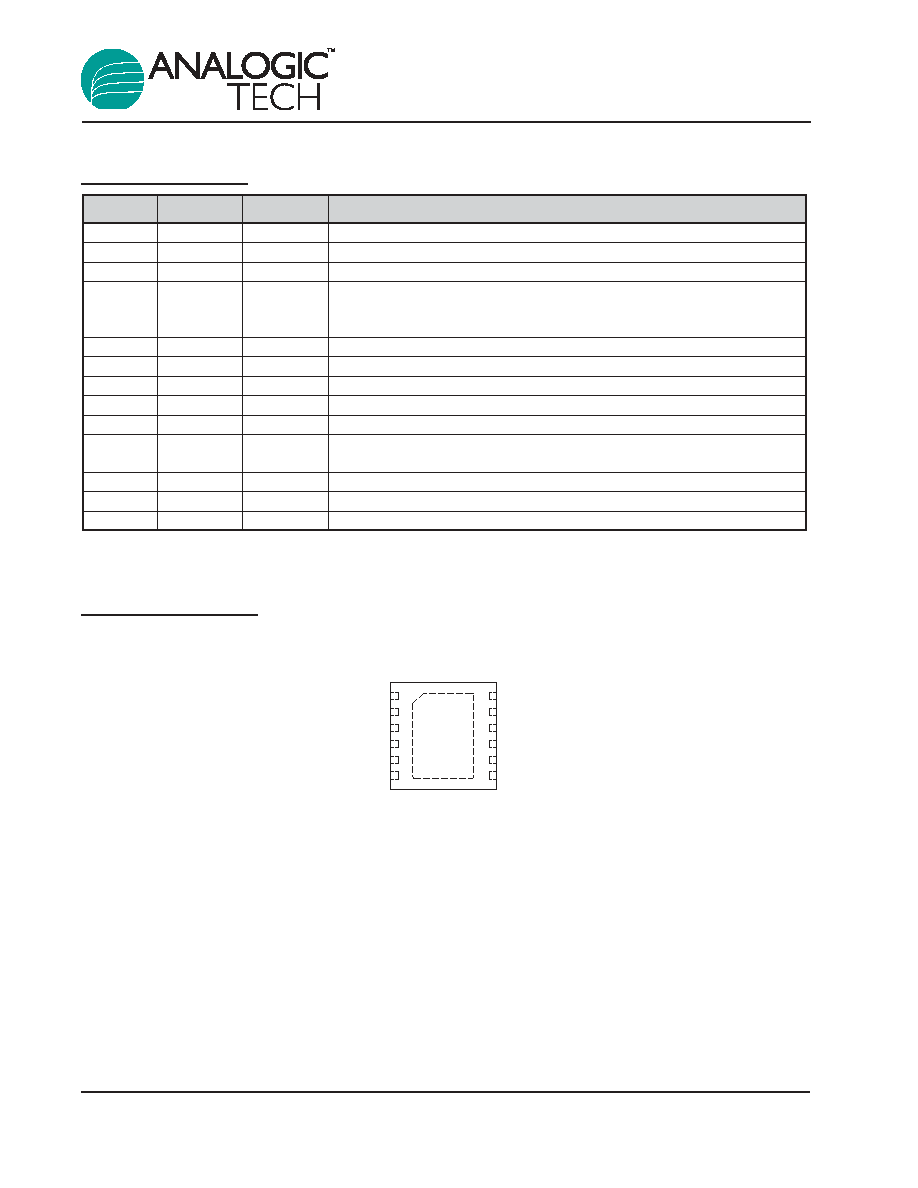
Pin Descriptions
Pin Configuration
TDFN33-12
(Top View)
ADP/USB
BAT
GND
1
CHR
EN
TS
SETH
SETL
PWRSEL
STAT1
STAT2
DATA
2
3
4
5
6
12
11
10
9
8
7
Pin #
Name
Type
Function
1
ADP/USB
In
Line adapter or USB power supply input.
2
BAT
In/Out
Battery charging and sensing.
3
GND
Ground
Ground connection.
4
CHR
In/Out
Resistor divider to set USB voltage regulation for charge reduction mode.
Leave this pin open for default 4.5V USB regulation point. Tie to ADP/USB
pin to disable this function.
5
EN
In
Enable pin. Logic high enables the IC.
6
TS
In/Out
Connect to 10k NTC thermistor.
7
DATA
In/Out
Status report to microcontroller via serial interface, open-drain.
8
STAT2
Out
Battery charge status indicator pin to drive an LED: active low, open-drain.
9
STAT1
Out
Battery charge status indicator pin to drive an LED: active low, open-drain.
10
PWRSEL
In
When ADP/USB is present, use this pin to toggle between SETH and SETL
charging levels.
11
SETL
In/Out
Connect resistor here to set charge current for low-current port.
12
SETH
In/Out
Connect resistor here to set charge current for high-current port.
EP
Exposed paddle (bottom); connect to GND directly beneath package.
AAT3685
Lithium-Ion/Polymer Battery Charger
2
3685.2006.02.1.2

Absolute Maximum Ratings
1
Thermal Information
2
Symbol
Description
Value
Units
JA
Maximum Thermal Resistance (3x3mm TDFN)
50
∞C/W
P
D
Maximum Power Dissipation
2.0
W
Symbol
Description
Value
Units
V
P
ADP/USB Input Voltage, <30ms, Duty Cycle <10%
-0.3 to 7.0
V
V
P
ADP/USB Input Voltage, Continuous
-0.3 to 6.0
V
V
N
BAT, PWRSEL, SETH, SETL, STAT1, STAT2, DATA, TS, CHR, EN
-0.3 to V
VP
+ 0.3
V
T
J
Operating Junction Temperature Range
-40 to 150
∞C
T
LEAD
Maximum Soldering Temperature (at leads)
300
∞C
AAT3685
Lithium-Ion/Polymer Battery Charger
3685.2006.02.1.2
3
1. Stresses above those listed in Absolute Maximum Ratings may cause permanent damage to the device. Functional operation at condi-
tions other than the operating conditions specified is not implied. Only one Absolute Maximum Rating should be applied at any one time.
2. Mounted on an FR4 board.

Electrical Characteristics
1
V
ADP
= 5V, T
A
= -25∞C to +85∞C, unless otherwise noted. Typical values are at T
A
= 25∞C.
Symbol
Description
Conditions
Min
Typ
Max Units
Operation
ADP/USB Input Voltage Range
4.0
5.5
V
V
UVLO
Under-Voltage Lockout
Rising Edge
3.0
V
Under-Voltage Lockout Hysteresis
150
mV
I
OP
Operating Current
CC Charge Current = 500mA
0.75
1.5
mA
I
SLEEP
Sleep Mode Current
V
BAT
= 4.25V
0.3
1.0
µA
I
Leakage
Reverse Leakage Current from
V
BAT
= 4V, ADP/USB Pin
1.0
µA
BAT Pin
Open
Voltage Regulation
V
BAT_EOC
1
End of Charge Voltage Accuracy
4.158
4.2
4.242
V
V
BAT
/V
BAT
EOC Voltage Tolerance
0.5
%
V
MIN
Preconditioning Voltage Threshold
2.8
3.0
3.15
V
V
RCH
Battery Recharge Voltage Threshold
V
BAT_EOC
- 0.1
V
V
ADP/USB_CHR
Charge Reduction Regulation
No Connection on CHR Pin
4.3
4.5
4.64
V
V
CHR
CHR Pin Voltage Accuracy
1.9
2.0
2.1
V
Current Regulation
I
CH
Charge Current
50
1000
mA
I
CH
/I
CH
Charge Current Regulation
10
%
Tolerance
V
SETH
SETH Pin Voltage
CC Mode
2.0
V
V
SETL
SETL Pin Voltage
CC Mode
2.0
V
K
IUH
Current Set Factor: I
CHARGE
/I
SETH
2000
K
IUL
Current Set Factor: I
CHARGE
/I
SETL
2000
Charging Devices
R
DS(ON)U
Charging MOSFET Transistor
V
IN
= 5.5V
0.4
0.5
0.65
On Resistance
AAT3685
Lithium-Ion/Polymer Battery Charger
4
3685.2006.02.1.2
1. The AAT3685 output charge voltage is specified over the 0∞ to 70∞C ambient temperature range; operation over the -25∞C to +85∞C
temperature range is guaranteed by design.

Electrical Characteristics
1
V
ADP
= 5V, T
A
= -25∞C to +85∞C, unless otherwise noted. Typical values are at T
A
= 25∞C.
Symbol
Description
Conditions
Min Typ
Max Units
Logic Control / Protection
V
PWRSEL(H)
Input High Threshold
1.6
V
V
PWRSEL(L)
Input Low Threshold
0.4
V
V
EN(H)
Input High Threshold
1.6
V
V
EN(L)
Input Low Threshold
0.4
V
V
STAT
Output Low Voltage
STAT Pin Sinks 4mA
0.4
V
I
STAT
STAT Pin Current Sink Capability
8.0
mA
V
OVP
Over-Voltage Protection Threshold
4.4
V
Pre-Charge Current I
TK
/I
CHG
For SETH Mode
10
%
For SETL Mode
50
Charge Termination Threshold Current
For SETH Mode
7.5
%
I
TERM
/I
CHG
Charge Termination Threshold Current
For SETL Mode
35
%
I
TERM
/I
CHG
I
TS
Current Source from TS Pin
70
80
90
µA
TS1
TS Hot Temperature Fault
Threshold 310 330
350
mV
Hysteresis
15
TS2
TS Cold Temperature Fault
Threshold 2.2
2.3
2.4
V
Hysteresis
10
mV
I_DATA
DATA Pin Sink Current
DATA Pin is Active Low State
3.0
mA
V
DATA(H)
Input High Threshold
1.6
V
V
DATA)(L)
Input Low Threshold
0.4
V
SQ
PULSE
Status Request Pulse Width
Status Request
200
ns
t
PERIOD
System Clock Period
50
µs
f
DATA
Data Output Frequency
20
kHz
T
OVSD
Over-Temperature Shutdown Threshold
145
∞C
AAT3685
Lithium-Ion/Polymer Battery Charger
3685.2006.02.1.2
5
1. The AAT3685 output charge voltage is specified over the 0∞ to 70∞C ambient temperature range; operation over the -25∞C to +85∞C
temperature range is guaranteed by design.