Available on Tape
and Reel For Pick and
Place Manufacturing.
USA/Canada:
Toll Free:
Europe
:
(315) 432-8909
(800) 544-2414
+44 2392-232392
Model 1H1304-30
Rev. B
Directional Couplers
30 dB
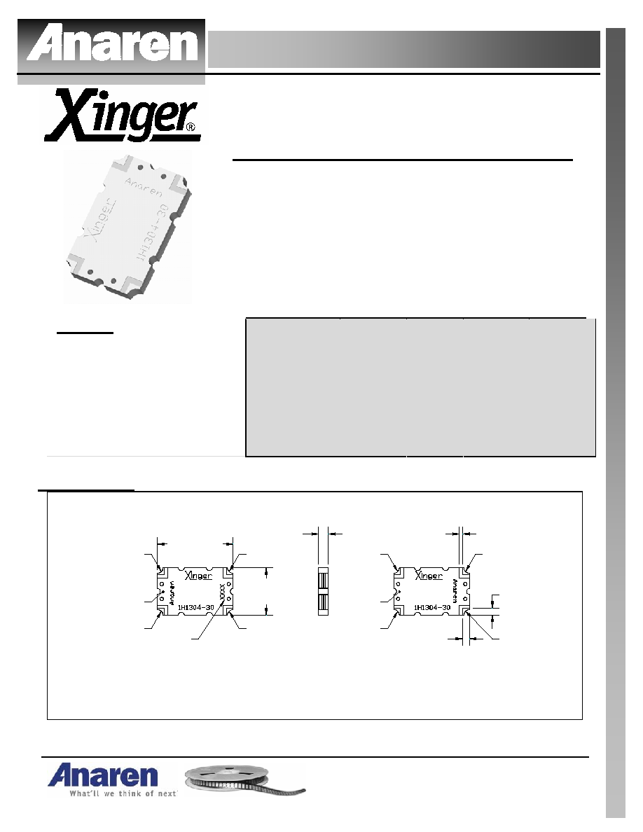
Description
The 1H1304-30 is a low profile 30dB directional coupler in an easy to
use surface mount package covering the AMPS and GSM bands. The
1H1304-30 is ideal for power and frequency detection as well as VSWR
monitoring and can be used in most high power designs. Parts have
been subjected to rigorous qualification testing and units are 100% tested.
They are manufactured using materials with x and y thermal expansion
coefficients compatible with common substrates such as FR4, G-10 and
polyamide.
ELECTRICAL
SPECIFICATIONS**
Frequency
Mean
Coupling
Insertion
Loss
VSWR
Freq.
Sensitivity
MHz
dB
dB Max
Max:1
dB Max
869 - 894
30 ± 2.5
0.25
1.20
±0.10
800 - 1000
30 ± 2.5
0.25
1.27
±0.30
Directivity
Power
Handling
JC
Operating
Temp.
dB Min
Watts
ºC / Watt
ºC
18
150
9.6
-55 to +85
Features:
· 800 - 1000 MHz
· Low loss
· High Directivity
· Surface Mountable
· Tape And Reel
· Convenient Package
· 100% Tested
18
150
9.6
-55 to +85
**Specification based on performance of unit properly installed on microstrip printed circuit
boards with 50
nominal impedance. Specifications subject to change without notice.
Outline Drawing
1H1304-30 Rev B Mechanical Outline
Dimensions are in Inches [Millimeters]
Bottom View (Far-side)
Side View
Top View (Near-side)
.073
±.007
[1.85
±0.18
]
.560
±.010
[14.22
±0.25
]
.350
±.010
[8.89
±0.25
]
.050
±.008
[1.27
±0.20
]
.050
±.008
[1.27
±0.20
]
Pin 4
Pin 4
Pin 3
Pin 1
Pin 2
Denotes
Array Number
GND
Pin 2
Pin 1
Pin 3
.024
±.004
TYP
[0.61
±0.10
]
Part Is Symmetric About All Axis
GND
USA/Canada:
Toll Free:
Europe:
(315) 432-8909
(800) 544-2414
+44 2392-232392
Available on Tape and
Reel For Pick and Place
Manufacturing.
Model 1H1304-30
Rev. B
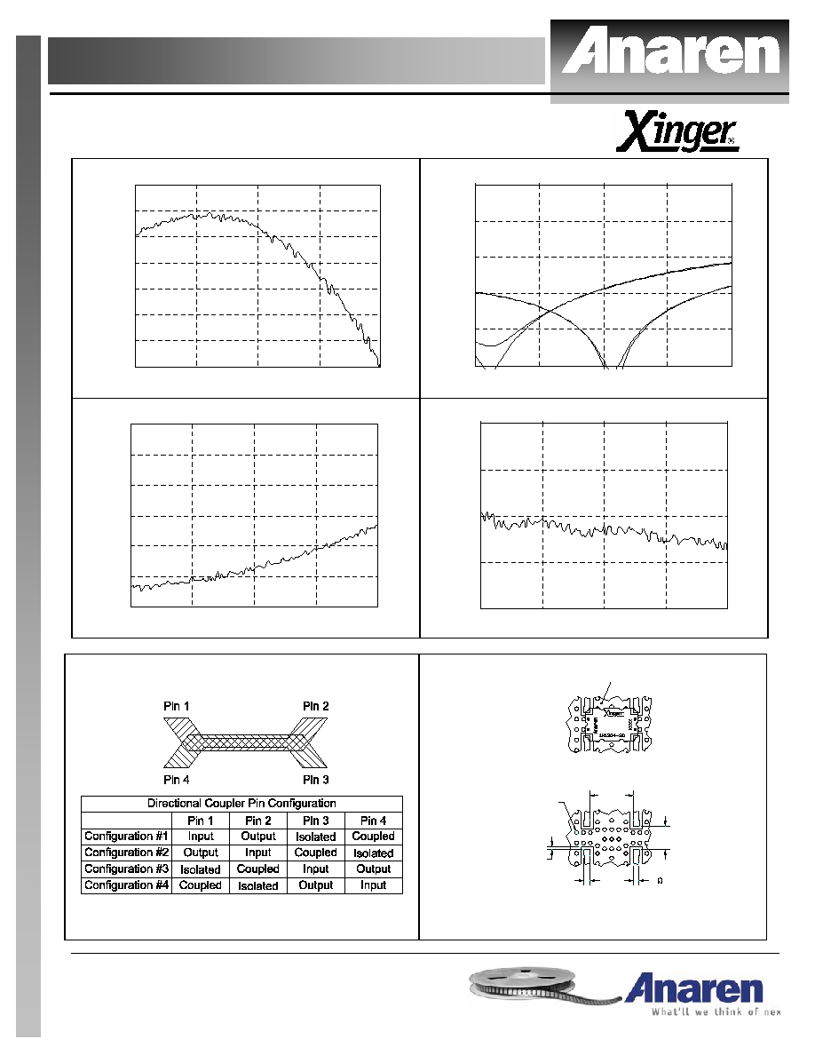
Typical Performance: 700 MHz. to 1300 MHz.
Coupling 1H1304-30
-32.5
-32.0
-31.5
-31.0
-30.5
-30.0
-29.5
-29.0
700
850
1000
1150
1300
Frequency [MHz]
Coupling [dB]
Return Loss 1H1304-30
-50
-40
-30
-20
-10
0
700
850
1000
1150
1300
Frequency [MHz]
Retur
n
Loss [dB]
Directivity 1H1304-30
-30
-25
-20
-15
-10
-5
0
700
850
1000
1150
1300
Frequency [MHz]
D
i
rectivity [dB
]
Transmission Loss 1H1304-30
-0.4
-0.3
-0.2
-0.1
0.0
700
850
1000
1150
1300
Frequency [MHz]
T
r
an
sm
issio
n
L
o
ss [d
B]
Pin Configuration
Mounting Footprint
To ensure proper electrical and thermal performance
there must be a ground plane with 100%
solder connection underneath the part
.063 SQ TYP
[1.60]
50
Transmission
Line
Dimensions are in Inches [Millimeters]
1H1304-30 Rev B Mounting Footprint
.250
[6.35]
.460
[11.68]
Part Is Symmetric About All Axis
.034 TYP
[0.86]
Multiple
plated thru holes
to ground
Available on Tape
and Reel For Pick and
Place Manufacturing.
USA/Canada:
Toll Free:
Europe
:
(315) 432-8909
(800) 544-2414
+44 2392-232392
Model 1H1304-30
Rev. B
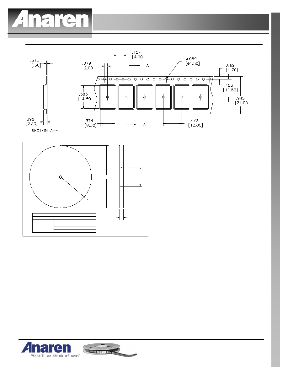
Carrier Tape _
Reel
B
ØA
ØC
REEL DIMENSIONS (inches [mm])
ØA
B
ØC
0.945 [24.0]
4.0 [101.6]
13.0 [330.2]
2000
QUANTITY/REEL
TABLE 1
ØD
0.512 [13.0]
ØD
· Parts are available in both reel and tube
· Quantity of 30 parts available per tube