Available on Tape
and Reel For Pick and
Place Manufacturing.
USA/Canada:
Toll Free:
Europe
:
(315) 432-8909
(800) 544-2414
+44 2392-232392
Model 1W1304-3
Rev. A
Hybrid Couplers
3 dB, 90
∞
Description
The 1W1304-3 is a low profile 3dB hybrid coupler in an easy to use surface
mount package covering the AMPS and GSM bands. The 1W1304-3 is
ideal for balanced amplifiers and signal distribution and can be used in most
high power designs. The 1W1304-3 has modified RF pads for improved
peak power handling and manufacturing reliability. Parts have been
subjected to rigorous qualification testing and units are 100% tested. They
are manufactured using materials with x and y thermal expansion
coefficients compatible with common substrates such as FR4, G-10 and
polyamide.
ELECTRICAL
SPECIFICATIONS**
Frequency
Isolation
Insertion
Loss
VSWR
MHz
dB Min
dB Max
Max:1
815 - 960
21
0.23
1.20
800 - 1200
20
0.25
1.25
Amplitude
Balance
Phase
Balance
Power
JC
Operating
Temp.
dB Max
Degrees
Ave. CW Watts
∫C/Watt
∫C
± 0.25
± 3
150
12.3
-55 to +85
Features:
∑ 800 ≠ 1200 MHz
∑ Low Loss
∑ High Isolation
∑ 90∞ Quadrature
∑ Surface Mountable
∑ Tape And Reel
∑ Convenient Package
∑ 100% Tested
± 0.40
± 3
150
12.3
-55 to +85
**Specification based on performance of unit properly installed on microstrip printed circuit boards
with 50
nominal impedance. Specifications subject to change without notice.
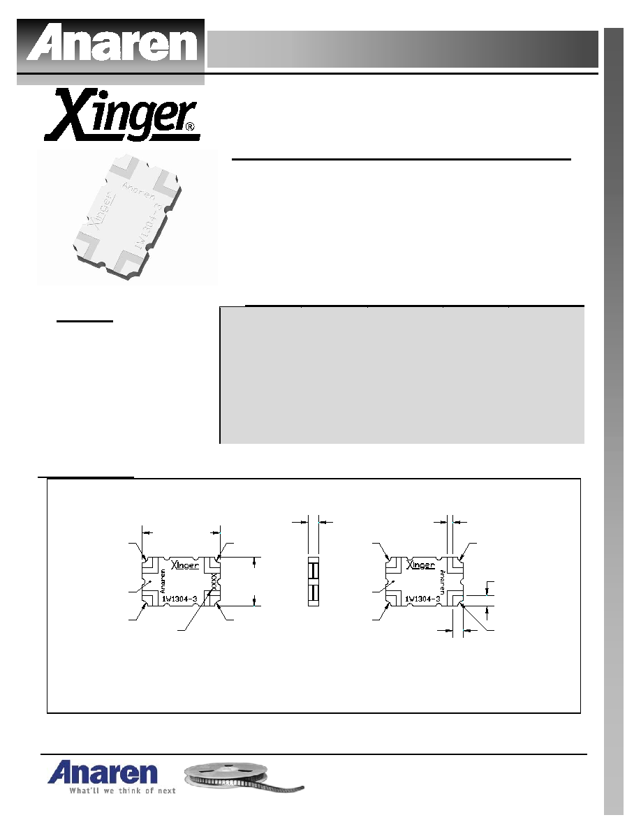
Outline Drawing
1W1304-3 Rev A Mechanical Outline
Dimensions are in Inches [Millimeters]
Bottom View (Far-side)
Side View
Top View (Near-side)
.076
±.008
[1.93
±0.20
]
.560
±.010
[14.22
±0.25
]
.350
±.010
[8.89
±0.25
]
.076
±.008
[1.93
±0.20
]
.076
±.008
[1.93
±0.20
]
Pin 4
Pin 3
Pin 1
Pin 2
Denotes
Array Number
GND
.037
±.004
TYP
[0.94
±0.10
]
Part Is Symmetric About All Axis
Pin 2
GND
Pin 1
Pin 3
Pin 4
USA/Canada:
Toll Free:
Europe:
(315) 432-8909
(800) 544-2414
+44 2392-232392
Available on Tape and
Reel For Pick and Place
Manufacturing.
Model 1W1304-3
Rev. A
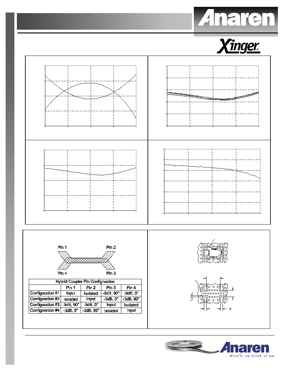
Typical Performance: 700 MHz. to 1300 MHz.
Coupling 1W1304-3
-3.8
-3.5
-3.2
-2.9
-2.6
700
850
1000
1150
1300
Frequency (MHz)
C
o
upl
i
ng (
d
B
)
Return Loss 1W1304-3
-50
-40
-30
-20
-10
0
700
850
1000
1150
1300
Frequency (MHz)
R
e
t
u
rn
L
o
s
s
(d
B
)
Isolation 1W1304-3
-50
-40
-30
-20
-10
700
850
1000
1150
1300
Frequency (MHz)
I
s
ol
at
i
on (
d
B
)
Phase Balance 1W1304-3
-93
-92
-91
-90
-89
-88
-87
700
850
1000
1150
1300
Frequency (MHz)
P
has
e
B
a
la
nc
e
(
D
eg
r
e
es
)
Pin Configuration
Mounting Footprint
To ensure proper electrical and thermal performance
there must be a ground plane with 100%
solder connection underneath the part
Dimensions are in Inches [Millimeters]
1W1304-3 Rev A Mounting Footprint
Part Is Symmetric About All Axis
Multiple
plated thru holes
to ground
.406
[10.31]
.034 TYP
[0.86]
.078 SQ TYP
[1.98]
50
Transmission
Line
.196
[4.98]