Available on Tape
and Reel For Pick and
Place Manufacturing.
USA/Canada:
Toll Free:
Europe
:
(315) 432-8909
(800) 544-2414
+44 2392-232392
Model 4A1305
Rev. A
Power Dividers
In-Phase, 2-Way
Description
The 4A1305 is a low profile 2 way Wilkinson power divider in an easy to use
surface mount package designed for DCS, PCS, ISM and wireless LAN
applications. The 4A1305 is ideal for low power, in phase divider/combiner
applications. Parts have been subjected to rigorous qualification testing
and units are 100% tested. They are manufactured using materials with x
and y thermal expansion coefficients compatible with common substrates
such as FR4, G-10 and polyamide.
ELECTRICAL
SPECIFICATIONS**
Frequency
Isolation
Insertion Loss
Amplitude
Balance
GHz
dB Min
dB Max
dB Max
1.7 � 2.0
16
0.35
�0.20
1.4 � 2.6
12
0.40
�0.25
VSWR
Input
VSWR
Output
Phase Balance
Operating
Temp.
Max:1
Max:1
Degrees
�C
1.30
1.30
� 2
-55 to +85
Features:
� 1.4 - 2.6 GHz
� Low loss
� High Isolation
� In Phase
� Surface Mountable
� Tape And Reel
� Convenient Package
� 100% Tested
1.50
1.35
� 2.5
-55 to +85
**Specification based on performance of unit properly installed on microstrip printed circuit
boards with 50
nominal impedance. Maximum input power: 5 Watts average CW when
terminated into a 1.2:1 maximum VSWR. Specifications subject to change without notice.
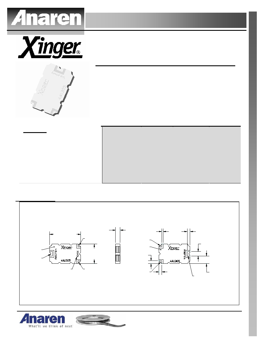
Outline Drawing
4A1305 Rev A Mechanical Outline
Dimensions are in Inches [Millimeters]
Bottom View (Far-side)
Side View
.081
�.008
[2.05
�0.20
]
.560
�.010
[14.22
�0.25
]
.350
�.010
[8.89
�0.25
]
Top View (Near-side)
.050
�.008
[1.27
�0.20
]
.050
�.008
[1.27
�0.20
]
.024
�.004
TYP
[0.61
�0.10
]
.080
�.004
[2.03
�0.10
]
.050
�.008
[1.27
�0.20
]
Pin 1
Pin 3
Pin 2
GND
GND
Pin 2
Pin 3
.135
�.008
[3.43
�0.20
]
Pin 1
Denotes
Array Number

USA/Canada:
Toll Free:
Europe:
(315) 432-8909
(800) 544-2414
+44 2392-232392
Available on Tape and
Reel For Pick and Place
Manufacturing.
Model 4A1305
Rev. A
Typical Performance: 1 GHz. to 3 GHz.
Insertion Loss 4A1305
-4
-3.8
-3.6
-3.4
-3.2
-3
1000
1250
1500
1750
2000
2250
2500
2750
3000
Frequency (MHz)
I
n
s
e
r
t
i
on Los
s
(
d
B
)
Return Loss 4A1305
-50
-40
-30
-20
-10
0
1000
1250
1500
1750
2000
2250
2500
2750
3000
Frequency (MHz)
R
e
t
u
rn
L
o
s
s
(d
B
)
Isolation 4A1305
-40
-30
-20
-10
1000
1250
1500
1750
2000
2250
2500
2750
3000
Frequency (MHz)
I
s
o
l
at
i
o
n (
d
B
)
Phase Balance 4A1305
-2
-1
0
1
2
1000
1250
1500
1750
2000
2250
2500
2750
3000
Frequency (MHz)
P
h
a
s
e B
a
l
a
n
c
e (D
eg
re
es
)
Pin Configuration
Mounting Footprint
OUTPUT
PIN - n
OUTPUT
PIN 2
n-WAY
POWER
DIVIDER
COMBINER
INPUT
PIN 1
OUTPUT
PIN - n
OUTPUT
PIN 2
n-WAY
POWER
DIVIDER
INPUT
PIN 1
DIVIDER
Dimensions are in Inches [Millimeters]
4A1305 Rev A Mounting Footprint
50
Transmission
Line
.085
[2.16]
To ensure proper electrical and thermal performance
there must be a ground plane with 100%
solder connection underneath the part
.080
[2.03]
.060
[1.52]
.250
[6.35]
.063 SQ TYP
[1.60]
.460
[11.68]
.034 TYP
[0.86]
Mutiple
plated thru holes
to ground