APEX MICROTECHNOLOGY CORPORATION ∑ TELEPHONE (520) 690-8600 ∑ FAX (520) 888-3329 ∑ ORDERS (520) 690-8601 ∑ EMAIL prodlit@apexmicrotech.com
1
INTRODUCTION
This easy-to-use kit provides a platform for the evaluation of
linear power amplifiers circuits using the MP230FC/MP240FC
pin out. With ample bread boarding areas it is flexible enough
to analyze a multitude of standard or proprietary circuit con-
figurations. Critical connections for power supply bypassing
are pre-wired. Components not usually readily available in
engineering labs are provided. External connection to the evalu-
ation kit can be made via the terminal block and the banana
jacks at the edges of the circuit board. Additionally, an optional
BNC connector can be inserted into the hole at the edge of
the board and wired to the number 5 terminal pad.
BEFORE YOU GET STARTED
∑
All Apex amplifiers should be handled using proper ESD
precautions.
∑
Do not change connections while the circuit is powered.
∑
Initially set all power supplies to the minimum operating
voltage allowed in the device data sheet.
PARTS LIST
Ref Apex Part #
Descrip/Vendor
Qty
NA
HS28
Heat Sink
1
NA
HS26
Heat Sink
1
NA
MS11
Cage jack strip
2
BJ1-4
BJ1
Banana Jack/
4
Deltron 164-6218
NA
EVAL45
PC Board
1
NA
60SPG00004 Spacer Grommets/
4
Micro Plastics
C1-4
OX7R105KWN 1uF Cap/
4
Novacap 1825B105K201N
TS1 TS02 Terminal Strip 1
C5,6*
EC05
2200uF 100V/
2
United Chemi-Con
82DA222M100KC2D
C5,6*
EC03
680uF 200V/
2
United Chemi-Con
KMH200VN681M25MX40T2
RLIM*
CSR17
0.025 Ohm Resistor/
1
Isotek PBV-R025-1
RLIM*
CSR18
0.050 Ohm Resistor/
1
Isotek PBV-R050-1
RLIM*
CSR19
0.100 Ohm Resistor/
1
Isotek PBV-R100-1
Rs1-Rs4 NA
Separate purchase required 4
See text.
*Chosen per directions
FIGURE 1. EVAL45 Schematic

APEX MICROTECHNOLOGY CORPORATION ∑ 5980 NORTH SHANNON ROAD ∑ TUCSON, ARIZONA 85741 ∑ USA ∑ APPLICATIONS HOTLINE: 1 (800) 546-2739
2
EVALUATION KIT FOR
MP230FC/MP240FC PIN OUT
EK52
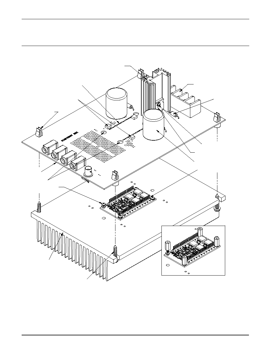
ASSEMBLY
During assembly refer to Figure 3 and the data sheet for the prod-
uct you are using, either the MP230FC or MP240FC.
1 Note that four balancing resistors, Rs1-Rs4, are required
for this evaluation kit and that these resistors are not sup-
plied. Each application will require different values and
so these resistors must be purchased by the user before
construction of the kit begins. See the recommendation in
the product data sheet as to the type of resistor needed
and a convenient source for purchasing the resistors.
Do not be tempted to operate the amplifier without these
resistors.
2. Note that each side of the circuit board is identified as
either the "Component Side" or "DUT Side."
3. Locate the two pre-loaded 30-position cage jack carrier
strips. Use wire cutters to cut off and discard 10 positions
from one of the carrier strips. From the "DUT Side " of the
PCB insert this carrier strip into the mounting holes for pins
1-20 of the amplifier and solder from the "Component Side"
of the PCB. Be sure that the cage jacks are fully seated
before soldering. Be careful that solder does not flow into
the cage jack.
4. In a similar manner to step 3 cut off 8 positions from the
remaining carrier strip, insert and solder into the mounting
holes for amplifier pins 21-42.
5. Pull out and discard each of the carriers.
6. Solder the surface mount capacitors at C1, C2, C3, and
C4 on the "Component Side" of the PCB.
7. Solder the surface mount balancing resistors that you
purchased separately at Rs1-Rs4 on the "Component
Side" of the PCB.
8. Mount the four horizontal banana jacks at locations BJ1-
4 and a BNC connector, if desired (not supplied), to the
PCB pad at location 5. Solder from the "DUT Side" of the
PCB.
9. Mount the terminal strip to the "Component Side" of the
PCB. Make sure the terminal strip is fully seated and solder
the pins from the "DUT Side" of the PCB. Be sure to fill
the mounting holes with solder.
10. Mount the electrolytic capacitors at C5 and C6 from the
"Component Side" of the PCB. Match the polarity markings
on the capacitor with the polarity markings on the PCB.
Use the correct voltage capacitors for the product you are
using: 100V capacitors for the MP230 and 200V capacitors
for the MP240. Be sure the capacitors have snapped into
the PCB and solder from the "DUT Side" of the PCB. Be
sure to fill the holes with solder.
11. Several low ohm value resistors are provided with this
evaluation kit: 0.025 ohm, 0.050 ohm and 0.100 ohm.
These are used to implement current limiting in the output
circuit. Select the value most appropriate for your applica-
tion. Refer to the product data sheet to determine which
resistor value you should use.
12. Mount the HS28 heat sink to the PCB and solder the
mounting tabs of the heat sink.
13. Apply a thin layer of thermal grease on the back of the
chosen current limiting sense resistor, insert the resistor
into the PCB and mount the resistor to the HS28 heat sink
using #4 screw and nut hardware (not supplied). Solder
the leads of the current limiting resistor from the "DUT
Side" of the board. Be sure to fill the mounting holes with
solder.
14. Mount other components and wiring as needed to com-
plete your application circuit using the pads and holes
provided.
15. From the "DUT side" of the PCB snap the spacer- grommets
into the holes at the four corners of the PCB. Notice that
the holes are slightly rectangular and match the spacer-
grommet's long and short sides to the holes in the PCB.
16. Apply a thin layer of thermal grease to the amplifier base.
Position the amplifier over the mounting holes in the HS26
heat sink. Firmly push the amplifier onto the heat sink
while slightly rotating the amplifier back and forth, ending
with the mounting holes of the amplifier over the mounting
holes in the heat sink.
17. Attach the amplifier to the heat sink with 4 4-40 X Ω" male-
female hex spacers (not supplied). These spacers serve
as alignment pins and aide in the assembly of the PCB to
the heat sink. Alternately, use 4-40 X º" machine screws
to mount the amplifier to the heat sink. Do not over-tighten
the spacers or screws as this provides no thermal benefit
and may break the hardware.
18. Place the PCB assembly onto the HS26 heat sink so that
the four hex spacers come through the aligning holes
near the four corners of the amplifier position in the PCB.
Carefully lower the PCB assembly until the pins of the
amplifier engage the cage jacks. Alternately, sight through
the aligning holes in the PCB and match-up the PCB to the
screws used to mount the amplifier. In either case be sure
the pins of the amplifier are engaged with the cage jacks
and then continue pushing the PCB assembly in the area
between the amplifier's pins until the 4 spacer grommets
at the four corners of the PCB touch the HS26 heat sink.
At this point you may need to push the PCB down slightly
in the area of the amplifier if the PCB is bowed.
19. Use #8 X 1" sheet metal screws (not provided) to mount
the PCB to the heat sink at the four spacer-grommets.
20. Hook up power and signals as necessary. The amplifier
is now ready for testing.