APEX MICROTECHNOLOGY CORPORATION ∑ TELEPHONE (520) 690-8600 ∑ FAX (520) 888-3329 ∑ ORDERS (520) 690-8601 ∑ EMAIL prodlit@apexmicrotech.com
1
PRELIMINARY
INTRODUCTION
The EK62 evaluation kit is designed to provide a convenient
way to breadboard design ideas for the SA305EX three ÿ BLDC
motor driver IC. The PB119 evaluation board is pre-wired for
all required and recommended external components including
the ones for power supply bypassing and current sensing. The
PB119 also includes a breadboard area for constructing your
application circuit.
PARTS LIST
Ref
ApexP/N
Description/Vendor
Qty
N/A
HS14
Heat Sink
1
029372326215 SIP Socket
1
Loranger
N/A
PB119
PC board
1
Many
571-0100
Banana Jack
22
Deltron
C1, C4 OX7R105KWN
1 µF cap
2
Novacap 1825B105K201N
C2, C5 140-ESRL100V100 100µF cap,
2
Xicon
N/A
TW12
Thermal Washer, Apex 1 Box
N/A
91920A865
Standoffs
4
McMaster-Carr
RecommendedComponents(includedinEKkit)
D1-D6 SB5100-T
Diode, 100V, 5A
6
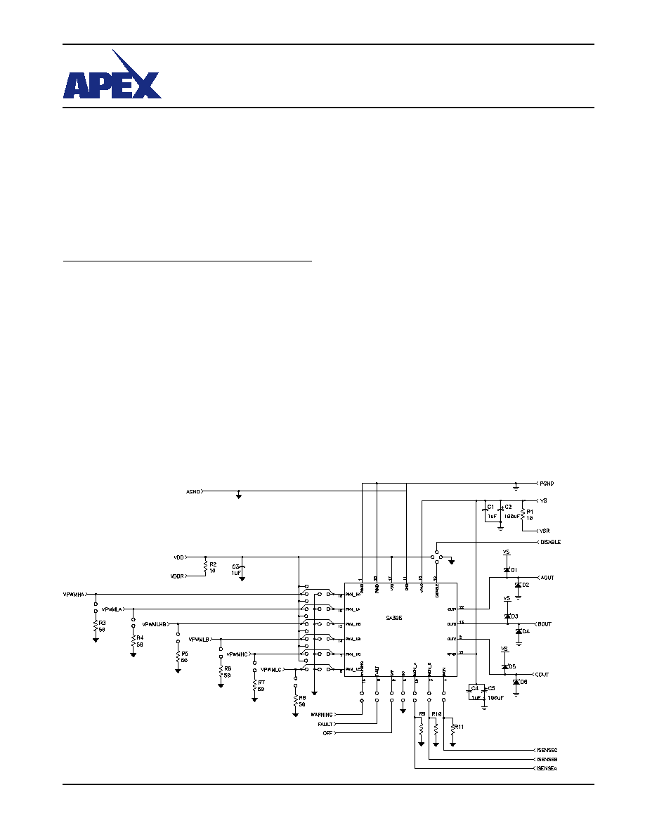
SCHEMATIC
M I C R O T E C H N O L O G Y
EK62
ASSEMBLY
1. Solder surface mount ceramic capacitors C1 and C4 on the
component side of the board.
2. Solder the SIP socket into the board. Insert the IC fully into
the socket, noting the pin 1 location on the IC and the circuit
board.
3. Add 3 resistors for current sense. Refer to SA305U data-
sheet for acceptable values and power dissipation ratings
of current sense resistors.
4. Install the banana jacks for signals and power. Please note
that the banana jacks need to be installed on both sides of
the board as shown in figure (only for low voltage signals
and Vdd on the bottom end of the board).
5. Mount the electrolytic capacitors C2 and C5 in the specified
location in the board.
6. Solder the diodes D1-D6 provided with the kit for high cur-
rent applications.
7. Mount the standoffs in the four holes provided in the
board.
8. If a heat sink is used, position the thermal washer behind
the package tab of the IC in such a way that the hole on
the washer coincides with the hole on the tab and the heat
sink. Attach the IC to the heat sink in such a way that the
pins hang out of the heat sink. In the PC board remove the
two standoffs on the top of the board. Carefully insert the
part with the heat sink into the socket.

APEX MICROTECHNOLOGY CORPORATION ∑ 5980 NORTH SHANNON ROAD ∑ TUCSON, ARIZONA 85741 ∑ USA ∑ APPLICATIONS HOTLINE: 1 (800) 546-2739
2
PCB
LAYOUT
EK62
PCB LAYOUT
This data sheet has been carefully checked and is believed to be reliable, however, no responsibility is assumed for possible inaccuracies or omissions. All specifications are subject to change without notice.
EK62U REV 1 FEBRUARY 2006 © 2006 Apex Microtechnology Corp.
PRELIMINARY