
A
PLUS
AVxx16 Series
www.aplusinc.com.tw
Page / 9 2002-Rev.2
1
GENERAL DESCRIPTION:
The AVH316B, AVH316C, AVH316D, AV0716C, AV0716D, AV1416D, AV2116A, AV2816A is a single-chip synthesizing CMOS VLSI that can synthesize voice
up to 3.5,7,14,21,28 seconds using APLUS qualified coding algorithm (LOGPCM).
Customer speech data will be edited and programmed into ROM by changing one mask during one mask during the device fabrication.
FEATURES:
1. Single power supply can operate from 2.4v through 5v.
2. The total voice duration is about 3.5,7,14,21,28,42 seconds could be partitioned up to 16 voice sections.
Each voice section could have 4 playing lengths; the longest one is the origional voice+mute length.
3. Voice + mute length could up to 22 seconds ( 11 seconds in AVH316 ) (6k sampling rate) for each voice section.
4. One 112 voice-steps table, could be partitioned up to 16 subtables of steps.
5. 5 mask option of playback speed : 1> 4.3K ; 2> 5.0K ; 3> 6.0K ; 4> 7.5K ; 5> 10.0K ( Hz )
6. 1 trigger input (TG): with resistive schmitt input (270K---1M) for CDS interface.
sequential function : once the input was triggered sequentially the device will response by one subtable of voice_step
sequentially and cyclically , from subtable_m ( m= 1 -16 ) to user defined subtable_n ( n= 1 - 16 ) .
random function : Once the input was trigger , the device will response from subtable_m ( m: 1 - 16 ) to subtable_n
( n: 1 - 16 ) at random .
snooze function : use 2 subtables : 1st stores ringing voice , playing when time's up.
2nd stores ( greeting sound + ) snooze time .
7.Has two debounce time : 10 ms, 50 us. with following mask option
A>50us B>10ms C>IO1(VDD-50us,GND-10ms) D>IO2(VDD-50us,GND-10ms) E>IO3(VDD-50us,GND-10ms)
C,D,E;could only be selected when IO1,IO2,IO3 are mask_option as control input .
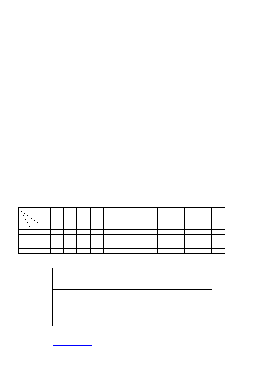
8. Automatic Rosc selection : enable - the device will use external Rosc if it has external Rosc ; the device will use internal Rosc
automatically if it hasn't external Rosc . ( It must be determined before operation )
disable - use external Rosc only . IO2 - VDD : disable GND : enable
Internal Rosc options : (mask option)
For VH316B ,AVH316C ,AVH316D ,AV0716C ,AV0716D ,AV1416D ,AV2116A , AV2816A :
playback
speed(khz)
A
B
C
D
E
F
G
H
I
J
K
L
M
4.3
8.9
8.6
7.9
7
6.3
5.8
5.4
5.1
4.7
4.3
4.1
3.9
3.6
5
10.3
10
9.2
8.2
7.3
6.8
6.3
5.9
5.5
5
4.8
4.6
4.2
6
12.4
12
11
9.8
8.8
8.1
7.5
7.1
6.6
6
5.7
5.5
5
7.5
15.5
15
13.8
12.3
11
10.1
9.4
8.9
8.3
7.5
7.1
6.9
6.3
10
20.7
20
18.3
16.3
14.7
13.5
12.5
11.8
11
10
9.5
9.2
8.3

A
PLUS
AVxx16 Serie
www.aplusinc.com.tw
Page / 9 2002-Rev.2
2
9. Playing mode :EDGEL/LEVEL , HOLD/UNHOLD , RETRIGGER/IRRETRIGGER with following mask options :
EDGE/LEVEL HOLD/UNHOLD RETRIGGERING/IRRETRIGGER
A>EDGE A>HOLD A>IRRETRIGGER
B>LEVEL B>UNHOLD B>RETRIGGER
C>IO1(VDD-edge.GND-level) C>IO1(VDD-hold,GND-unhold) C>IO1(VDD-irretrigger,GND-retrigger)
D>IO2(VDD-edge.GND-level) D>IO2(VDD-hold,GND-unhold) D>IO2(VDD-irretrigger,GND-retrigger)
E>IO3(VDD-edge.GND-level) E>IO3(VDD-hold,GND-unhold) E>IO3(VDD-irretrigger,GND-retrigger)
C, D, E could only be selected when IO1,IO2,IO3 are mask_option as control input .
10. 3 I/O PINS WITH FOLLOWING OPTIONS:
* IO1 * IO2 * IO3
A>COUT B>STOPH C>STOPL A>PWM1 B>STOPH C>STOPL A>PWM2 B>STOPH C>STOPL
D>BUSYH E>BUSYL F>6HZ D>BUSYH E>BUSYL F>6HZ D>BUSYH E>BUSYL F>6HZ
G>DYNA1/4 H>DYN2/4 I>DYN3/4 G>DYNA1/4 H>DYN2/4 I>DYN3/4 G>DYNA1/4 H>DYN2/4 I>DYN3/4
J>USED AS CONTROL INPUT J>USED AS CONTROL INPUT J>USED AS CONTROL INPUT
Item_F : 0.75Hz or 1.5Hz or 3Hz or 6Hz(mask option)
Item_B~I : with one subtable enable status option for IO1, IO2, IO3.
COUT : 3 current output levels, with 4 mask options (1.5mA;3mA;4.5mA;IO3<GND-3mA,VDD-4.5mA>).
PWM1, PWM2 : must be selected on the same time ,direct driving buzzer or 8 or 32 or 64 ohm speaker.
STOPH, STOPL : 40 ms high/low output when device stop playing.(drive 1.8 mA,sink 10mA;3v).
BUSYH, BUSYL : high/low output during device playing (drive 1.8 mA,sink 10mA;3v).
6Hz/3Hz, DYNA1/4, 2/4, 3/4 : LED driving. (drive 1.8 mA, sink 10mA;3v)
Used as control input : internal pull GND (0.5uA,3V)
For all the IO options : the dynamic should choice same level.
If IO2 and IO3 are both at 6Hz(3Hz), they will flash alternatively.
When used as control input, they could be used to control following options by bonding or toggle switch.
EDGE/LEVEL, HOLD/UNHOLD, RETRIGGER/IRRETRIGGER, DEBOUNCE 10ms/50us
:
AVH316B ,AVH316C ,AVH316D ,AV0716C ,AV0716D ,AV1416D ,AV2116A,AV2816A CMOS
VLSILOGPCM3.5714212842
ROM
1. 2.4 - 5
2. 3.571421284216(section)
(
+)
A
PLUS
AVxx16 Serie
www.aplusinc.com.tw
Page / 9 2002-Rev.2
3
3. (+) 22( 11in AVH316 ) (6kHz
)
4. 112(VOICE - STEPS)16(subtable)
5. 5:1>4.3k ; 2>5k ; 3>6k ; 4>7.5k ; 5>10k Hz
6. (TG)(270K-1M)(CDS)
(SEQUENTIAL)(subtable) 1 (subtable
n ; n=1 - 16 )
(RANDOM)m (m)n(n
) ,
(SNOOZE),1 2
7. (DEBOUNCE)10ms-, 50us-,
A>50us , B>10ms , C>IO1(VDD-50us,GND-10ms) , D>IO2(VDD-50us,GND-10ms) ,
E>IO3(VDD-50us,GND-10ms) ,
C,D,E ,IO1,IO2,IO3
8. ():
A).
- ,;,
(
B).
-
C).
IO2VDD - GND -
D).
()
For
AVH316B ,AVH316C ,AVH316D ,AV0716C ,AV0716D ,AV1416D ,AV2116A ,
AV2816A :
A
B
C
D
E
F
G
H
I
J
K
L
M
4.3
8.9
8.6
7.9
7
6.3
5.8
5.4
5.1
4.7
4.3
4.1
3.9
3.6
5
10.3
10
9.2
8.2
7.3
6.8
6.3
5.9
5.5
5
4.8
4.6
4.2
6
12.4
12
11
9.8
8.8
8.1
7.5
7.1
6.6
6
5.7
5.5
5
7.5
15.5
15
13.8
12.3
11
10.1
9.4
8.9
8.3
7.5
7.1
6.9
6.3
10
20.7
20
18.3
16.3
14.7
13.5
12.5
11.8
11
10
9.5
9.2
8.3
9.
/
(EDGE / LEVEL)
/
( HOLD / UNHOLD)
/
(RETRIGGER /
IRRETRIGGER)
I01 (VDD- GND-)
I02 (VDD- GND-)
I03 (VDD- GND-)
I01 (VDD-GND-)
I02 (VDD-GND-)
I03 (VDD-GND-)
I01(VDD-,GND-
)
I02(VDD-,GND-
)
I03(VDD-,GND-
)
C,D,E ,IO1,IO2,IO3
A
PLUS
AVxx16 Serie
www.aplusinc.com.tw
Page / 9 2002-Rev.2
4
10.I/O PINS
IO1
IO2
IO3
A) COUT
B) .
C) .
D) .
E) .
F) LED 6HZ.
G) LED 1/4.
H) LED 2/4.
I) LED 3/4.
J)
A) PWM1
B).
C) .
D) .
E) .
F) LED 6HZ.
G) LED 1/4.
H) LED 2/4.
I) LED 3/4.
J)
A) .PWM2
B).
C) .
D) .
E) .
F) LED 6HZ.
G) LED 1/4.
H) LED 2/4.
I) LED 3/4.
J)
F : LED 0.75HzLED 1.5HzLED 3Hz
LED 6Hz
B � I :, IO1, IO2IO3(subtable)
COUT3, 4 (1.5mA3.0mA4.5mA IO3<GND-3mA,VDD-4.5mA> )
PWM1PWM2 buzzer 83264 ohm speaker
IO1IO2IO3(0.5uA3v)
IO1 - IO3 LED.
IO2IO3LED 6HZ(3HZ)
IO1IO2IO3
EDGE/LEVEL, HOLD/UNHOLD, RETRIGGER/IRRETRIGGER, DEBOUNCE 10ms/50us
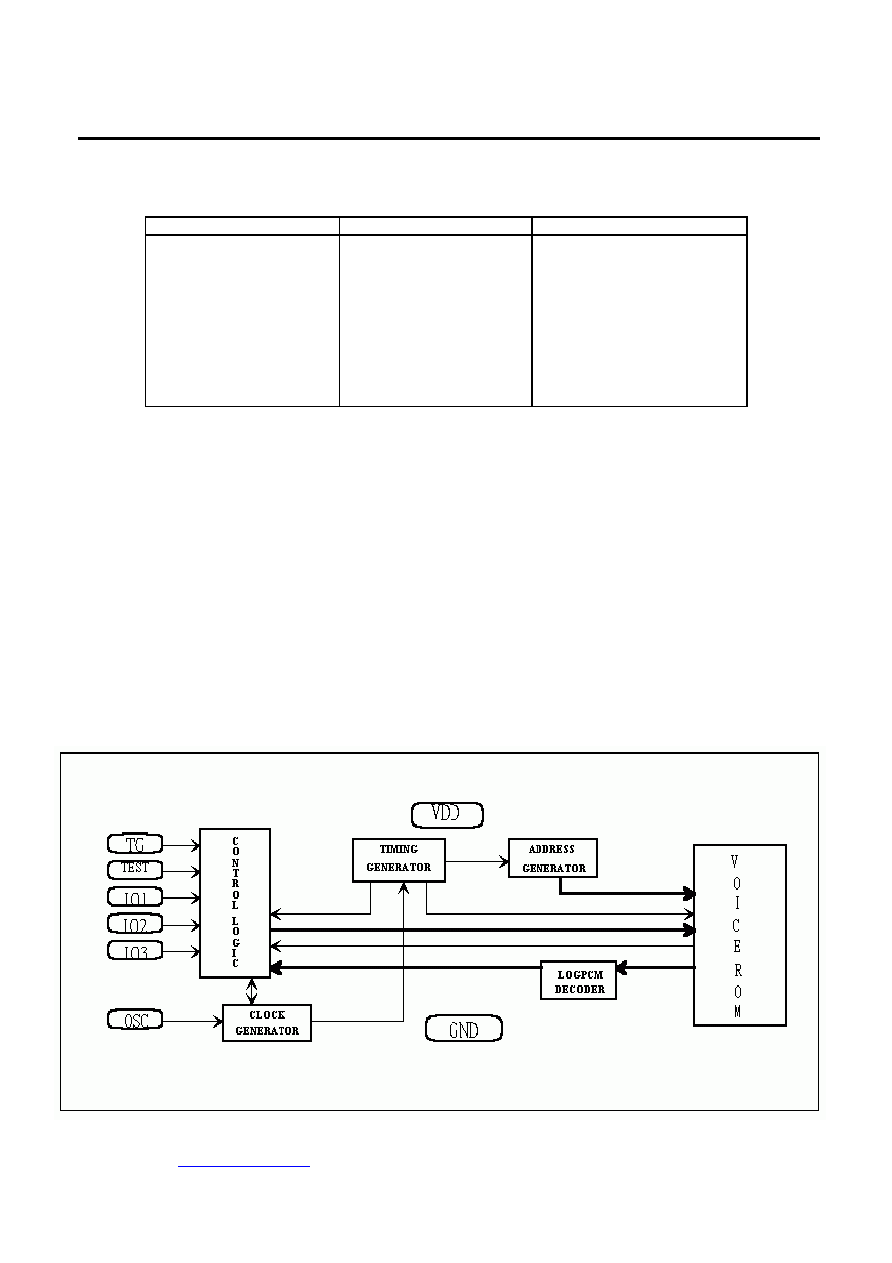
BLOCK DIAGRAM:

A
PLUS
AVxx16 Serie
www.aplusinc.com.tw
Page / 9 2002-Rev.2
5
PIN DESCRIPTION :
PAD NAME
PIN ATTR.
FUNCTION
VDD
POWER
POSITIVE POWER SUPPLY.
OSC
I
OSCILLATOR INPUT (300K ohm CONNECT TO VDD).
TEST
I
TEST PAD,FOR PRODUCTION TESTING (TEST HIGH FOR TESTING)
TG
I
TRIGGER INPUT, INTERNAL PULL LOW (HIGH ACTIVE).
IO1,IO2,IO3
I/O
AUDIO SIGNAL; STATUS OUTPUT; CONTROL INPUT.
VSS POWER
NEGATIVE
POWER
SUPPLY.
ABSOLUTE MAXIMUM RATING :
SYMBOL RATING UNIT
VDD~VSS -0.5~+7.0
V
VIN (FOR ALL INPUT)
VSS-0.3<VIN<VDD+0.3
V
VOUT (FOR ALL OUTPUT)
GND<VOUT<VDD
V
T (OPERATING)
0~+70
T (STORAGE)
-25~+75
DC CHARACTERISTICS :
SYMBOL PARAMETER
MIN.
TYP.
MAX.
UNIT
CONDITION
VDD OPERATING
VOLTAGE
2.4
3
5
V
Isb STANDBY
0.1
Iop
SUPPLY
CURRENT
OPERATING
200
uA VDD=3V
,I/O
OPEN
(WITH Rosc)
Iih
5
Iil
TG
0
uA VDD=3V
-1.2 -1.5 -1.8
-2.4 -3 -3.6
Ico
IO1
USE
AS
CURRENT OUT
(FULL SCALE)
-3.6 -4.5 -5.4
mA
VDD=3V, V O/P=0.7V
Iih
0.5
Iil
IO1,IO2,IO3
USE AS
CONTROL INPUT
0
uA VDD=3V
Ioh
min:-0.9
max:-1.4
VDD=3V, V O/P=0V
Iol
IO1,IO2,IO3
USE AS STATUS OUTPUT
DURING OPERATING
8 10 12
mA
VDD=3V, V O/P=3V
dF/F FREQUENCY
STABILITY
-10
10
%
Fosc(3v)-Fosc(2.4v)
Fosc (3v)
dF/F Fosc
VARIATION
-10
10
%
VDD=3V,Rosc=300K
(Rosc=180K in AV1416 )