 | –≠–ª–µ–∫—Ç—Ä–æ–Ω–Ω—ã–π –∫–æ–º–ø–æ–Ω–µ–Ω—Ç: AVXX32A | –°–∫–∞—á–∞—Ç—å:  PDF PDF  ZIP ZIP |

AVxx32A Series
Rev 1.0 2003/02/12
1
1. GENERAL DESCRIPTION:
The
AV1232E, AV1832D, AV2432C are single-chip voice synthesizing CMOS IC. They can synthesize
voice up to 12, 18 and 24 seconds, using
APLUS 5-bit LOGPCM algorithm. Customer speech data can
be edited and programmed into ROM by changing one mask during the device fabrication.
2. FEATURES:
(1). Single power supply can operate from 2.4V to
5V.
(2). The total voice duration is about 12, 18 or 24 seconds those can be partitioned up to 32 voice_sections.
Each voice_section length is flexible.
(3). Each voice_section can select 4 kinds of End_Address (i.e. 4 kinds of playing_length), the longest
playing_length is the voice+mute length. The voice+mute length can be up to 22 seconds for each
voice_section ( at 6kHz sample rate ).
(4). Total 255 voice_steps are available for 32 sub_tables. For each voice_step, it can specify one
voice_section, one playing_length of voice_section, one kind of playback speed and STS1, STS2, STS3,
STS4 output enable options.
8 kinds of playback speed: 1>5.0k ; 2>5.6k ; 3>6.2k ; 4>7.0k ; 5>8.0k ; 6>9.4k ; 7>11.3k ; 8>14.1k Hz
( With Rosc= 180k ohms at Vdd= 3V )
STS1, 2, 3, 4 output enable options: each output pin with one control bit. ( "0" enable, "1" disable )
(5). Three trigger input mode: MATRIX, ALONE and CPU_INTERFACE. ( Mask option )
In MATRIX and ALONE, there are Mode, Priority and Debounce selections.
One control input pin "MODE/STS4" can be used as Mode selection or STS4. ( Mask option )
MATRIX mode: 4x4 matrix inputs ; M1~M16 (ROW1~4 x COL1~4)
Mode selection: Mode=0 subtable1~16 ; Mode=1 subtable17~32.
Priority: M1>M2>M3>M4 ; M5>M6>M7>M8 ; M9>M10>M11>M12 ; M13>M14>M15>M16.
Debounce: 11ms or 1ms.
ALONE mode: 8 alone inputs ; A1~A8 (ROW1~4 + COL1~4)
Mode selection: Mode=0 subtable1~8 ; Mode=1 subtable9~16
Priority: A1>A2>A3>A4>A5>A6>A7>A8.
Debounce: 10ms or 50us
Each alone input can choose 1M+CDS, 10M or 10M+CDS pull-low input type.
If MODE/STS4 is selected for STS4 output, MATRIX is only subtable1~16 available and ALONE is only
subtable1~8 available.
In these 2 modes, all the trigger input can be assign as different playing mode with following options:

AVxx32A Series
Rev 1.0 2003/02/12
2
Edege/Level; Hold/UnHold; Retrigger/Irretrigger.
CPU_INTERFACE mode: Addressing access mode by input pulse count. In this mode, A1~A7
(ROW1~4, COL1~3) are disable, A8 (COL4) can be access up to 32 subtables.
(6). The A8 or M16 can be selected as NORMAL, SEQUENTIAL or CPU_INTERFACE. ( Mask option )
NORMAL: normal mode as in item (5).
SEQUENTIAL: can be selected to combine with MODE input or not. ( Mask option )
(A). If A8 or M16 is in SEQUENTIAL and is combined with MODE input:
MODE=0 : the device will response by one subtable sequentially and cyclically, from subtable1 to
user defined end subtable (subtable n, n=1~16).
MODE=1 : the device will response by one subtable sequentially and cyclically, from subtable 17
to user defined end subtable (subtable n, n=17~32).
The number of subtables (used in sequence) in MODE=1 and MODE=0 must be equal; this
number must be less than 16.
(B). If A8 or M16 is in SEQUENTIAL and is not combined with MODE input:
The device will response by one subtable sequentially and cyclically, from subtable1 to user
defined end subtable (subtable n, n=1~32).
The relationship between SEQUENTIAL ( A8/M16 ) and other inputs ( A1~A7 / M1~M15 ) can be
selected as RESET or UNRESET. ( Mask option )
RESET: once the other inputs are triggered, the SEQUENTIAL sequence will reset to subtable 1.
UNRESET: SEQUENTIAL sequence and other inputs are independent.
(7). Four STS pins have the following options: ( Mask option )
OUT1: Cout (Current output) or STS1 output
OUT2: PWM1 or STS2 output
OUT3: PWM2 or STS3 output
MODE/STS4: MODE selection or STS4 output
Cout has 3 current output levels: 1>1.5mA ; 2>3mA ; 3>4.5mA. ( full scale ; Vdd=3V )
PWM1 and PWM2 must be selected on the same time, they can directly drive buzzer or 8, 16, 32 or 64
ohms speaker.
AVxx32A Series
Rev 1.0 2003/02/12
3
(8). Four status outputs ( STS1, STS2, STS3, STS4 ):
STS1
STS2
a). Cout
b). stop high_pulse
c). stop low_pulse
d). busy high_active
e). busy low_active
f). LED 6Hz (flash at mute)
g). LED 3Hz (flash at mute)
h). LED 1.5Hz (flash at mute)
i). LED 0.75Hz (flash at mute)
j). LED 6Hz (off at mute )
k). LED 3Hz (off at mute)
l). LED 1.5Hz (off at mute )
m). LED 0.75Hz (off at mute)
n). LED dybzl 0.34sec.
o). LED dybzl 0.68sec.
p). LED dybzl 1.02sec.
q). busy high, except mute
r). busy low, except mute
a). PWM1
b). stop high_pulse
c). stop low_pulse
d). busy high_active
e). busy low_active
f). LED 6Hz (flash at mute)
g). LED 3Hz (flash at mute)
h). LED 1.5Hz (flash at mute)
i). LED 0.75Hz (flash at mute)
j). LED 6Hz (on at mute)
k). LED 3Hz (on at mute)
l). LED 1.5Hz (on at mute)
m). LED 0.75Hz (on at mute)
n). LED 6Hz (off at mute)
o). LED 3Hz (off at mute)
p). LED 1.5Hz (off at mute)
q). LED 0.75Hz (off at mute)
r). LED dynamic 1/4
s). LED dynamic 2/4
t). LED dynamic 3/4
STS3
STS4
a> PWM2
b> stop high_pulse
c> stop low_pulse
d> busy high_active
e> busy low_active
f> LED 6Hz (flash at mute)
g> LED 3Hz (flash at mute)
h> LED 1.5Hz (flash at mute)
i> LED 0.75Hz (flash at mute)
j> LED 6Hz (off at mute )
k> LED 3Hz (off at mute)
l> LED 1.5Hz (off at mute )
m> LED 0.75Hz (off at mute)
n> LED dybzl 0.34sec.
o> LED dybzl 0.68sec.
p> LED dybzl 1.02sec.
q> busy high, except mute
r> busy low, except mute
a). mode
b). stop high_pulse
c). stop low_pulse
d). busy high_active
e). busy low_active
f). LED 6Hz (flash at mute)
g). LED 3Hz (flash at mute)
h). LED 1.5Hz (flash at mute)
i). LED 0.75Hz (flash at mute)
j). LED 6Hz (on at mute)
k). LED 3Hz (on at mute)
l). LED 1.5Hz (on at mute)
m). LED 0.75Hz (on at mute)
n). LED 6Hz (off at mute)
o). LED 3Hz (off at mute)
p). LED 1.5Hz (off at mute)
q). LED 0.75Hz (off at mute)
r). LED dynamic 1/4
s). LED dynamic 2/4
t). LED dynamic 3/4
AVxx32A Series
Rev 1.0 2003/02/12
4
If both STS1(STS3) and STS2(STS4) are in 6Hz or 3Hz mode, they will flash alternatively.
For STS1 and STS3 options, the DYBZL must selected same level.
For STS2 and STS4 options, the DYNAMIC must selected same level.
STS4 was enabled only when the MODE/STS4 is in STS4 option.
For each voice_step, the STS1, STS2, STS3, STS4 can be mask_selected as active or inactive.
If select flash at mute of STS1(STS3), can select 3Hz or 1.5Hz or 0.75Hz.
If select flash at mute of STS2(STS4), can select 3Hz or 1.5Hz or 0.75Hz.
If both select off at mute of STS1(STS2,STS3,STS4) or on at mute of STS2(STS4), can only select
3Hz or 1.5Hz or 0.75Hz at the same level.
(9). Oscillator selection:
(A). External oscillator: Connect OSC pin to Vdd with a resister, Rosc.
(B). Internal oscillator: Connect OSC pin to GND.
(C). There are 8 playback speeds for options whether selecting external or internal oscillator.
When external Rosc is 180k ohms at 3V, there are 8 kinds of playback speed as in item (4). If you
change the value of Rosc, the 8 kinds of playback speed will be changed accordingly and equally.
Therefore, you can change the Rosc to change the range of 8 playback_speeds.
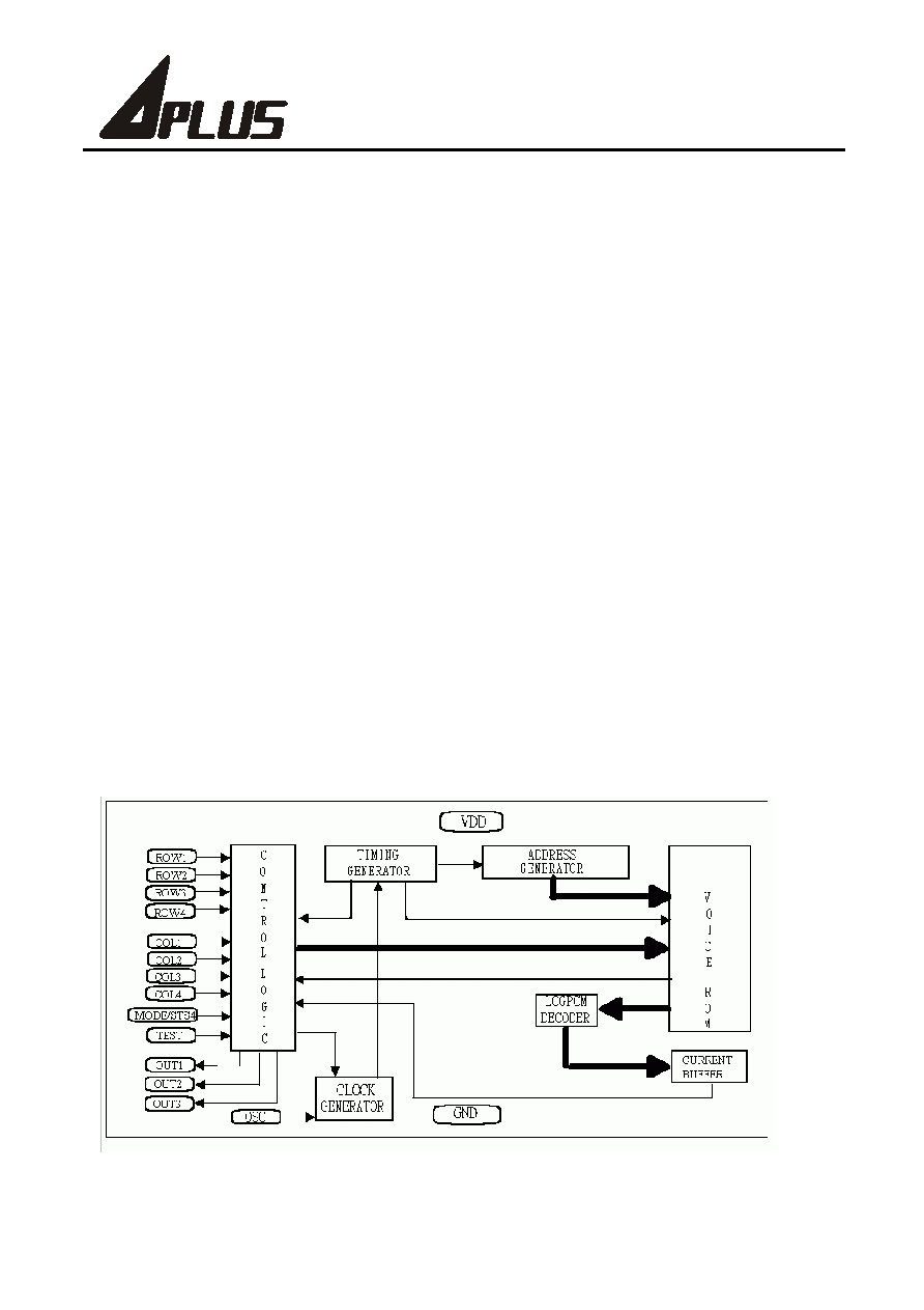
3. BLOCK DIAGRAM:

AVxx32A Series
Rev 1.0 2003/02/12
5
1. :
A
V1232EAV1832DAV2432C CMOS IC 5-bit LOGPCM
121824 ROM
2. :
(1). 2.4 ~
5
(2). 121824 32(voice_section)
(3). (4)"+
""+" 22 (6kHz)
(4). 255(voice_step)32(sub_table)
STS1STS2STS3STS4
8: 1> 5.0k ; 2> 5.6k ; 3> 6.2k ; 4> 7.0k ; 5> 8.0k ; 6> 9.4k ; 7> 11.3k ; 8> 14.1k Hz
( Vdd=3V ; Rosc=180k ohms )
STS1234 : ( "0" ; "1" )
(5). 3: (Matrix) (Alone) CPU( )
MODE
"MODE/STS4" MODE STS4( )
4◊4M1~M16 (ROW1~4 x COL1~4)
MODEMODE=01~16MODE=117~32
M1>M2>M3>M4; M5>M6>M7>M8; M9>M10>M11>M12; M13>M14>M15>M16
(DEBOUNCE)11ms--; 1ms--
A1~A8 (ROW1~4 + COL1~4)
MODEMODE=01~8MODE=19~16
A1>A2>A3>A4>A5>A6>A7>A8
(Debounce)10ms--50us--
1M+CDS10M 10M+CDS pull-low
MODE/STS4STS41~161~8
2() / (Edge/Level) ; /
(Hold/UnHold) ; / (Retrigger/Irretrigger)
CPUA8 (COL4) CPU (ROW1~4,
COL1~3)