
LOW TO MEDIUM POWER AC/DC POWER SUPPLIES 80-110W AC/DC Universal Input Switch Mode Power Supplies
1
2 YEAR WARRANTY
NFS110 Series
S i n g l e a n d q u a d o u t p u t
∑
7.0 x 4.25 x 1.8 inch package
∑
Overvoltage and short circuit protection
∑
110W with 20CFM
∑
Adjustable outputs
∑
EN55022, EN55011 conducted emissions level B
∑
UL, VDE and CSA safety approvals
∑
CE mark
The NFS110 series is a 110W universal input AC/DC power supply on a 7 x 4.25 inch
card. The NFS110 series has four single and three quad output models and has proven
itself to be highly reliable and versatile product for a wide range of communication and
industrial applications, with a very high peak current capability on each output for drive
and motor applications. The NFS110 provides 80W of output power with free air
convection cooling which can be boosted to 110W with 20CFM of air. Standard
features include overvoltage and short circuit protection. The series, with full
international safety approval and the CE mark, meets conducted emissions EN55022
level B. The NFS110 series is designed for use in low power data networking,
computer, telecom and industrial applications such as servers, thermal printers, storage
devices, vending machines and POS equipment.
All specifications are typical at nominal input, full load at 25∞C unless otherwise stated
GENERAL SPECIFICATIONS
Hold-up time
110VAC @ 80W
35ms
110VAC @ 110W
17ms
230VAC @ 80W
140ms
230VAC @ 110W
100ms
Efficiency
Multiple outputs
70% typical
+5.1V single
70% typical
12V and 15V singles
72% typical
24V single
75% typical
Isolation voltage
Input/output
3000VAC
Input/chassis
1500VAC
Switching frequency
At 100 Watts output
20 to 70kHz
At zero load
100 to 250kHz
Approvals and
VDE0805, EN60950, IEC950
standards
IEC1010, UL1950
(See Note 12)
CSA C22.2 No. 950
Weight
Singles
550g (19.4oz)
Multiple outputs
600g (21.2oz)
MTBF (See Note 9)
MIL-HDBK-217E
125,000 hours
ENVIRONMENTAL SPECIFICATIONS
Thermal performance
Operating, see curve
0∞C to +70∞C
(See Notes 9, 10)
Non-operating
≠40∞C to +85∞C
0∞C to +50∞C,
80W
amb. convection cooled
+50∞C to +70∞C,
Derate 2W/∞C
amb. convection cooled
0∞C to +50∞C,
110W
20CFM forced air
+50∞C to +70∞C,
Derate
20CFM forced air
2.75W/∞C
Peak, 0∞C to +50∞C,
110W
max. 60 seconds
Relative humidity
Non-condensing
5% to 95% RH
Altitude
Operating
10,000 feet max.
Non-operating
40,000 feet max.
Vibration (See Note 11)
5Hz to 500Hz
2.4G approx.
OUTPUT SPECIFICATIONS
Voltage adjustability
+5.1V output on multi's
±3.0%
5.1V single output
±3.0%
12V single output
12V to 14V
15V single output
15V to 18V
24V single output
24V to 30V
Line regulation
LL to HL, FL
±0.1% max.
All outputs on all units
Overshoot/undershoot
At turn-on
0%
Temperature coefficient
All outputs
±0.02%/∞C
Overvoltage protection
Multi output 5.1V only
6.25V±0.75V
5.1V single
6.25V±0.75V
12V single
15.75V±1.0V
15V single
22V±1.5V
24V single
33V±2.5V
Output power limit
Primary power
Pin max. 160W
limited
Pout min. 110W
Minimum output current
(See Note 13)
0A
Short circuit protection
Burst mode operation
INPUT SPECIFICATIONS
Input voltage range
85 to 264VAC
120 to 370VDC
Input frequency range
47Hz to 440Hz
Input surge current
230VAC
35A
Safety ground
110VAC, 50Hz
0.2mA, max.
leakage current
230VAC, 50Hz
0.4mA, max.
EMC CHARACTERISTICS
Conducted emissions
EN55022, FCC part 15
Level B
Radiated emissions
EN55022, FCC part 15
Level A
ESD air
EN61000-4-2, level 3
Perf. criteria 1
ESD contact
EN61000-4-2, level 4
Perf. criteria 1
Surge
EN61000-4-5, level 3
Perf. criteria 1
Fast transients
EN61000-4-4, level 3
Perf. criteria 1
Radiated immunity
EN61000-4-3, level 3
Perf. criteria 2
Conducted immunity
EN61000-4-6, level 3
Perf. criteria 1
SPECIFICATIONS
File Name: NFS110.PDF Rev: 01 Jan 2000

For the most current data and application support visit www.artesyn.com/powergroup/products.htm
Notes
1
Convection cooled, 80W maximum.
2
Peak outputs lasting less than 60 seconds with duty cycle less than 10%.
Total peak power must not exceed 110W.
3
Forced air, 20CFM at 1 atmosphere, 110W maximum.
4
Figure is peak-to-peak. Output ripple is measured across a 50MHz
bandwidth using a 12 inch twisted pair terminated with a 47µF capacitor.
5
Total regulation is defined as the static output regulation at 25∞C, including
initial tolerance, line voltage within stated limits and output voltages
adjusted to their factory settings.
6
To achieve stated regulation on the 24V output on the NFS110-7602P, the
following load condition must be true: I
A
/ I
B
5, where:
I
A
= +5.1V output current, and
I
B
= +24V output current
The +24V output will maintain ±5.0% regulation under the following
additional condition: I
A
5A.
7
Single output models have floating outputs which may be referenced as
either positive or negative. Higher voltage supplies may be adjusted over a
wide output voltage range, as long as the total output power does not
exceed 80 Watts (natural convection) or 110 Watts (forced air).
8
Power fail detect not available on single output models.
9
Derating curve is application specific for ambient temperatures >50∞C, for
optimum reliability no part of the heatsink should exceed 90
o
C and no
semiconductor case temperature should exceed 100
o
C.
10
Caution: Allow a minimum of 1 second after disconnecting the power when
making thermal measurements.
11
Three orthogonal axes, random vibration, 10 minute test for each axis.
12
This product is only for inclusion by professional installers within other
equipment and must not be operated as a stand alone product.
13
Artesyn Technologies recommends a minimum load of 11W to achieve the
design MTBF. See the derating curve on page 3.
NFS110 Series
S i n g l e a n d q u a d o u t p u t
LOW TO MEDIUM POWER AC/DC POWER SUPPLIES 80-110W AC/DC Universal Input Switch Mode Power Supplies
2
www.artesyn.com
File Name: NFS110.PDF Rev: 01 Jan 2000
OUTPUT
OUTPUT CURRENTS
RIPPLE
(4)
TOTAL
MODEL NUMBERS
(F)
VOLTAGE
MAX
(1)
PEAK
(2)
FAN
(3)
REGULATION
(5)
+5.1V
8.0A
20.0A
10.0A
50mV
±2.0%
NFS110-7601P
+12.0V
4.5A
9.0A
5.0A
120mV
±3.0%
≠12.0V
0.5A
1.5A
1.0A
120mV
±3.0%
≠5.0V
0.5A
1.5A
1.0A
50mV
±3.0%
+5.1V (I
A
)
8.0A
20.0A
10.0A
50mV
±2.0%
NFS110-7602P
(6)
+24.0V (I
B
)
(6)
3.5A
4.5A
4.5A
240mV
+10/≠5.0%
+12.0V
4.5A
9.0A
5.0A
120mV
±3.0%
≠12.0V
0.5A
1.5A
1.0A
120mV
±3.0%
+5.1V
8.0A
20A
10A
50mV
±2.0%
NFS110-7604P
+15.0V
4.0A
7.5A
5A
150mV
±3.0%
≠15.0V
0.5A
1.5A
1.0A
150mV
±3.0%
≠5.0V
0.5A
1.5A
1.0A
50mV
±3.0%
5.1V
16.0A
22.0A
20.0A
50mV
±2.0%
NFS110-7605
(7,8)
12V
7.0A
9.0A
9.0A
120mV
±2.0%
NFS110-7612
(7,8)
15V
5.0A
7.3A
7.3A
150mV
±2.0%
NFS110-7615
(7,8)
24V
3.5A
4.5A
4.5A
240mV
±2.0%
NFS110-7624
(7,8)
TRANSIENT RESPONSE
NFS110-7601P
+5.1V (7.5A to 10A)
150mV peak,
1ms recovery
+12V (2.5A to 5A)
100mV peak,
0.5ms recovery
-12V (0.5A to 1A)
100mV peak,
0.5ms recovery
-5V (0.5A to 1A)
100mV peak,
0.5ms recovery
NFS110-7602P
+5.1V (7.5A to 10A)
150mV peak,
1ms recovery
+24V (1.5A to 3A)
300mV peak,
1ms recovery
+12V (2.5A to 5A)
100mV peak,
0.5ms recovery
-12V (0.5A to 1A)
100mV peak,
0.5ms recovery
NFS110-7604P
+5.1V (7.5A to 10A)
150mV peak,
1ms recovery
+15V (2.5A to 5A)
100mV peak,
0.5ms recovery
-15V (0.5A to 1A)
100mV peak,
0.5ms recovery
-5V (0.5A to 1A)
100mV peak,
0.5ms recovery
NFS110-7605
+5.1V (10A to 20A)
250mV peak,
1ms recovery
NFS110-7612
+12V (4.5A to 9A)
360mV peak,
1ms recovery
NFS110-7615
+15V (3.65A to 7.3A)
450mV peak,
1ms recovery
NFS110-7624
+24V (2.25A to 4.5A)
720mV peak,
1ms recovery
AC (J1) mating connector
Molex 09-50-3051 or Molex 09-91-0500 mating connector with 2478 or
equivalent crimp terminals.
DC (J2) mating connector
Molex 09-50-3131 or Molex 09-91-1300 mating connector with 2478 or
equivalent crimp terminals.
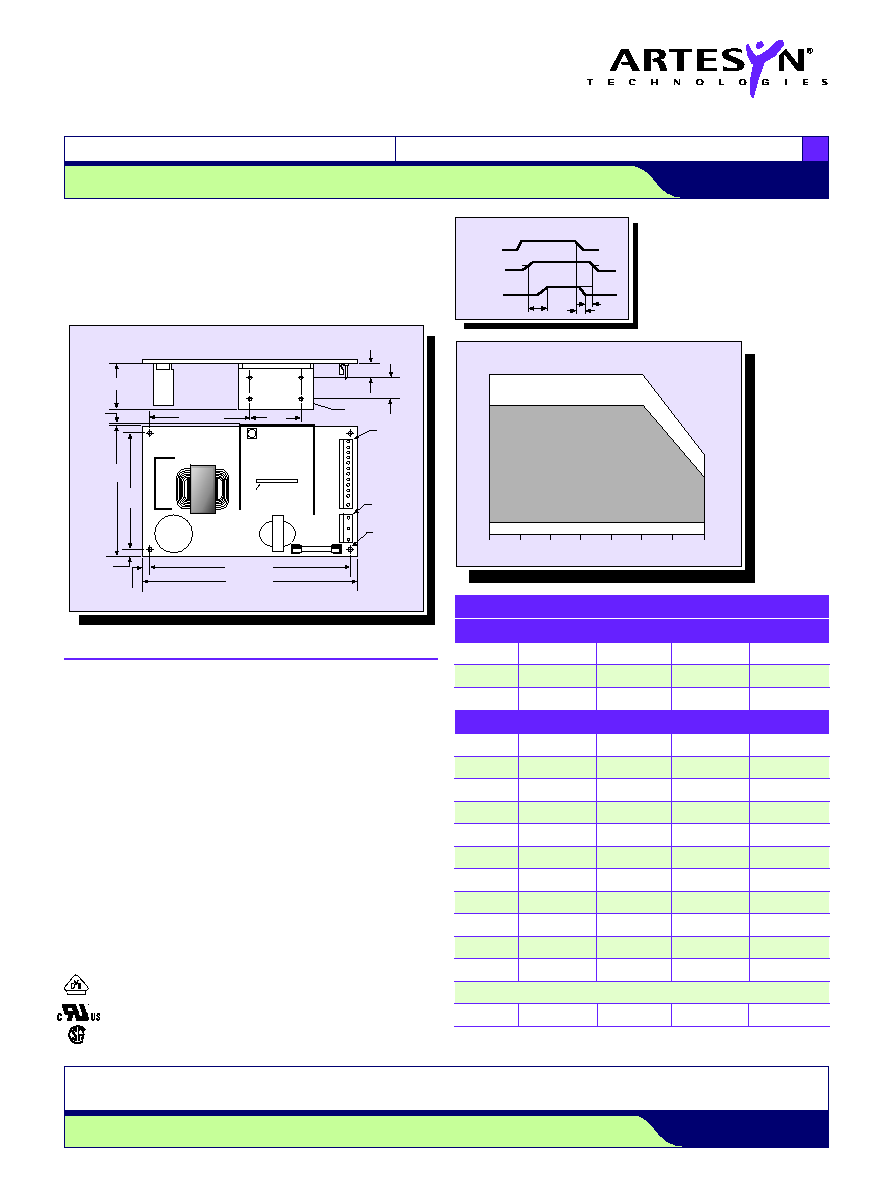
ALL DIMENSIONS IN INCHES (mm)
Optional
Power Fail
Detect Circuit
(Key = Pin 2)
Pin 1
6-32 UNC
(4PL)
PIN 1
1.00
±
0.005
(25.4)
Voltage Adjust
J2
J1
F1
L1
T1
C6
PIN 1
0.156
DIA. HOLE
(4PL)
5A, 250 VAC
0.475
±
0.010
(12.07)
1.55
±
0.005
(39.37)
3.35
±
0.015 (85.09)
1.80 (45.72) MAX
0.050
±
0.020
(1.27)
4.250
±
0.020
(107.95)
3.750
±
0.005
(95.25)
0.250
±
0.010
(6.35)
0.250
±
0.010
(6.35)
6.50
±
0.005 (165.1)
7.00
±
0.020 (177.8)
T1
Power fail detect signal (Note 8)
50ms
T1
200ms
T2 will vary with line and load
T3
3ms
Pout: 110W
PFD output is an open collector which
will sink
40mA in the low state.
HIGH
T1
T2
T3
4.75V
3.5V MIN
0-0.4 MAX
LOW
4.75V
5V OUTPUT
PFD SIGNAL
AC INPUT
OPTIONAL POWER FAIL DETECT TIMING DIAGRAM
110W
80W
20 CFM FORCED AIR COOLING
40W
55W
0W
11W
11W MINIMUM LOAD REQUIRED AT 230VAC
NATURAL
CONVECTION
COOLING
0
∞
C 10
∞
C 20
∞
C 30
∞
C 40
∞
C 50
∞
C 60
∞
C 70
∞
C
DERATING CURVE
(See Notes 9, 10)
Output Power (Watts)
N/C = no connection.
PIN CONNECTIONS
J1
≠7601P
≠7602P
≠7604P
SINGLES
Pin 1
AC Ground
AC Ground
AC Ground
AC Ground
Pin 2
AC Neutral
AC Neutral
AC Neutral
AC Neutral
Pin 3
AC Line
AC Line
AC Line
AC Line
J2
Pin 1
+5.1V
+5.1V
+5.1V
V
out
Pin 2
+5.1V
+5.1V
+5.1V
V
out
Pin 3
+5.1V
+5.1V
+5.1V
V
out
Pin 4
Return
Return
Return
Return
Pin 5
Return
Return
Return
Return
Pin 6
Return
Return
Return
Return
Pin 7
Return
Return
Return
Return
Pin 8
+12V
+12V
+15V
V
out
Pin 9
+12V
+12V
+15V
V
out
Pin 10
PFD
PFD
PFD
N/C
Pin 11
≠12V
≠12V
≠15V
N/C
Pin 12
Removed for Key
Pin 13
≠5V
+24V
≠5V
N/C
Data Sheet © Artesyn TechnologiesÆ 2002
The information and specifications contained in this data sheet are believed to be correct at time of publication. However, Artesyn Technologies accepts no responsibility for consequences arising
from printing errors or inaccuracies. Specifications are subject to change without notice. No rights under any patent accompany the sale of any such product(s) or information contained herein.
For the most current data and application support visit www.artesyn.com/powergroup/products.htm
NFS110 Series
S i n g l e a n d q u a d o u t p u t
LOW TO MEDIUM POWER AC/DC POWER SUPPLIES 80-110W AC/DC Universal Input Switch Mode Power Supplies
3
www.artesyn.com
File Name: NFS110.PDF Rev: 01 Jan 2000
International Safety Standard Approvals
VDE0805/EN60950/IEC950/IEC1010 File No. 10401-3336-1049
Licence No. 2874, 1653 and 1049
UL1950 File No. E136005
CSA C22.2 No. 950 File No. LR41062C
Mechanical Notes
A
Metallic or non-metallic stand-offs (maximum diameter 5.4mm) can be
used in all four mounting holes without effecting safety approval.
B
The ground pad of the mounting hole near J1, allows system grounding
through a metal stand-off to the system chassis.
C
The heat sink is grounded, and allows system grounding by mechanical
connection to the system chassis.
D
The supply must be mechanically supported using the PCB mounting holes
and may be additionally supported by the heatsink mounting holes.
E
It is always advisable to attach the power supply heat sink to another
thermal dissipator (such as a chassis or finned heatsink etc). The resulting
decrease in heat sink mounted component temperatures will improve
power supply lifetime.
F
A standard L-bracket and cover is available for mounting which contains all
screws, connectors and necessary mounting hardware. Two different kits
are available, order part number `NFS110 COVER KIT' or `NFS110C'.