File Name: rfb300_350.pdf Rev: 03 Feb 2006
2 YEAR WARRANTY
All specifications are typical at nominal input, full load at 25 ∞C unless otherwise stated.
External output capacitance required (See Note 4)
SPECIFICATIONS
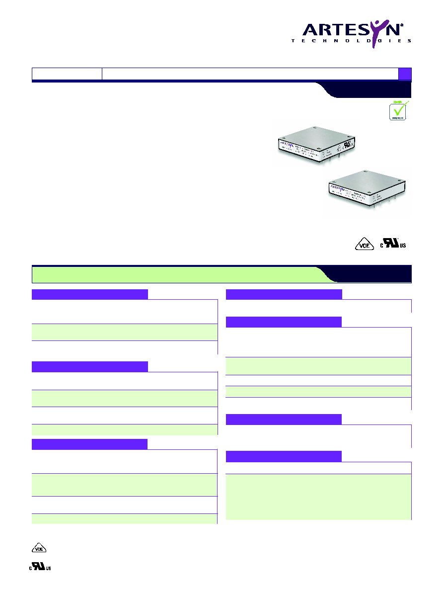
RFB300/350 series is a high efficiency, enclosed, isolated dc-dc converter series in
an industry standard half-brick package that provides up to 350 W of output power.
The series delivers very high usable output power for today's high performance RF
power amplifier and similar applications. The four models in the series feature an
input voltage range of 18 Vdc to 36 Vdc and 36 Vdc to 75 Vdc and an output
voltage of 12 V and 28 V. The output voltage is adjustable from 7.2 Vdc to 13.2 Vdc
or 16.8 Vdc to 29.4 Vdc (not to exceed 308 W for the RFB300 [300 W for the
RFB300-24S12] and 350 W for the RFB350). The series also has a remote ON/OFF
capability. Overcurrent, overvoltage and overtemperature protection features are
included as standard. Negative logic remote ON/OFF and other options are also
available. Full international safety approval including EN/IEC60950 VDE and
UL/cUL60950 reduces compliance costs and time to market.
∑
High efficiency topology
∑
Wide temperature range, -40 ∞C to +100 ∞C @ full power
∑
High power density (160 W/in
3
in 0.4" tall version)
∑
Input voltage range: 18-36 Vdc or 36-75 Vdc
∑
Output voltage range: 7.2-13.2 Vdc or 16.8-29.4 Vdc
∑
Remote ON/OFF
∑
Operational insulation system
∑
Available RoHS compliant
RFB300/350 Series
2 4 V i n a n d 4 8 V i n s i n g l e o u t p u t
International Safety Standard Approvals
VDE0805/EN60950/IEC950 File No. 10401-3336-0198
Licence No. 40005395
UL/cUL CAN/CSA 22.2 No. 60950
UL 60950 File No. E135734
ABSOLUTE MAXIMUM RATINGS
Input voltage - peak
24 Vin
-0.5-50 Vdc
(100 ms max.,
48 Vin
-0.5-100 Vdc
1.0 % duty cycle max.)
Input voltage continuous 24 Vin
-0.5-40 Vdc
48 Vin
-0.5-80 Vdc
Adjust pin voltage (with
-0.5-12 Vdc
respect to -sense pin)
OUTPUT SPECIFICATIONS
Voltage adjustability
12 Vout
7.2-13.2 Vdc
28 Vout
16.8-29.4 Vdc
Min./max. load
12 Vout
0/25 A, 0/29.2 A
28 Vout
0/11 A, 0/12.5 A
Output load capacitance 12 Vout
470 µF to 4,700 µF
(See Note 10)
28 Vout
330 µF to 3,300 µF
Rise time
(See Note 12)
5 ms typ.
INPUT SPECIFICATIONS
Input current
24 Vin
23.8 A max. @ lo max.
(See Note 3)
48 Vin RFB300
11.2 A max. @ lo max.
48 Vin RFB350
13 A max. @ lo max.
Input reflected ripple
24 Vin
12 mA (pk-pk)
(See Note 4)
48 Vin 12 V model
42 mA (pk-pk)
48 Vin 28 V model
28 mA (pk-pk)
Input capacitance -
24 Vin
39 µF
Internal filter
48 Vin
13 µF
Inrush current
(See Note 11)
2 A
2
s
DC-DC CONVERTERS 300-350 W Half-Brick
1
NEW Product
EMC CHARACTERISTICS
Conducted emissions
EN55022
See Application Note 167
Radiated emissions
EN55022
See Application Note 167
GENERAL SPECIFICATIONS
Efficiency
24 Vin 12 V model
86%
24 Vin 28 V model
90%
Vin = Vin (nom),
48 Vin 12 V model
88%
Iout (max.)
48 Vin 28 V model
91%
Approvals and
VDE IEC60950
standards
IECEE CB, UL/cUL60950
Material Flammability
UL94V-0
Weight
0.5 inch tall version
110 g (3.88 oz.)
MTBF @ 55 ∫C
12 V model
1,900,000 hours min.
Telcordia SR-332 Issue 1 28 V model
2,400,000 hours min.
ENVIRONMENTAL SPECIFICATIONS
Thermal performance
Operating baseplate, -40 ∫C to +100 ∫C
temperature
Non-operating
-40 ∫C to +100 ∫C
RC PIN ELECTRICAL INTERFACE
Open collector compatible
(See AN 167 for remote ON/OFF)
RC:
ON voltage
(See Note 13)
5 V min.
Open circuit voltage
5 V min, 11 V typ
13 V max.
High level leakage current (See Note 14)
-25 µA max.
OFF voltage
(See Note 15)
1.2 V max.
Low level input current
(See Note 16)
-250 µA max.
N
No
otte
es
s
1
Measurement Bandwidth: 20 MHz; Measured with 1 µF ceramic and a
330 µF (470 µF for 12 V output model) aluminum or solid tantalum
capacitor across the output terminals.
2
Di/dt = 1 A/µs; I
out
= ±25% Iout (max); Vin = Vnom; Iout = Inom. Tested
with a 1 µF ceramic and a 330 µF (470 µF for 12 V output model)
aluminum electrolytic capacitor across the output.
3
External input fusing required. Use a fast acting fuse: 40 A (24 V model),
15 A (48 V, 350 W model).
4
Iout = Iout (max) Measured with the input capacitor, Cbypass = 330 µF,
and 6 µH inductor in series with the power source. Frequencies
>100 kHz.
5
Signal line assumed <3 m in length.
6
This product is only for inclusion by professional installers within other
equipment and must not be operated as a stand-alone product.
7
Negative remote ON/OFF option also available. Add suffix `-R' to part
number, for example see part numbering system.
8
With the enable signal asserted, this is the time from when the input
current reaches 10 % of the final steady state value until the output
voltage reaches 10 % of the nominal output value. Start-up into resistive
load.
9
With Vin > Vin (min.) applied for a minimum of 1 second, this is the time
from when the primary ON/OFF signal is activated until the output
voltage reaches 10 % of the nominal output voltage.
10
Minimum effective ESR is 1 m. Minimum phase margin is 35∫.
11
Measured per ETSI 300 132-2 Section 4.7.2.
12
From 10% to 90% of Vout (nom). Full resistive load. 1 µF ceramic and
330 µF (470 µF for 12 V model) electrolytic capacitors across the output.
N
No
otte
es
s C
Co
on
nttd
d..
10
Minimum effective ESR is 1 m. Minimum phase margin is 35∫.
11
Measured per ETSI 300 132-2 Section 4.7.2.
12
From 10% to 90% of Vout (nom). Full resistive load. 1 µF ceramic and
330 µF (470 µF for 12 V model) electrolytic capacitors across the output.
13
Converter guaranteed ON for positive option.
14
Maximum driver leakage to insure converter is ON.
15
Converter guaranteed OFF for positive option.
16
Driver sink current @ Vrc 1.2 V.
17
0.40 in height option is not available on the 12 V output model.
18
The'Y' suffix indicates that these parts are TSE ToHS 5/6 (non-Pb-free)
compliant
19
NOTICE: Some models do not support all options. Please contact your
local Artesyn representative or use the on-line model number search tool
at http://www.artesyn.com/powergroup/products.htm to find a suitable
alternative
PROTECTION
Short-circuit
12 V model RFB300
29.4 A
(Brickwall current
12 V model RFB350
34.4 A
limiting)
28 V model RFB300
12.9 A
28 V model RFB350
14.7 A
Overvoltage protection
12 V model
15 V
(Output shutdown)
28 V model
33.2 V
Overtemperature
(midpoint of baseplate)
110 ∫C
shutdown
File Name: rfb300_350.pdf Rev: 03 Feb 2006
For the most current data and application support visit www.artesyn.com/powergroup/products.htm
DC-DC CONVERTERS 300-350 W Half-Brick
2
NEW Product
R F B 3 0 0 - 2 4 S 2 8 - R 5 T Y
Part Number System with Options
Output Voltage
12 = 7.2 Vdc to 13.2 Vdc
28 = 16.8 Vdc to 29.4 Vdc
Remote ON/OFF Polarity
R = Negative Logic Option
Blank = Positive Logic Option
Height Option
(17)
5 = 0.50 in (12.70 mm)
4 = 0.40 in (10.16 mm)
Threaded Inserts
T = Threaded Inserts
Blank = Clearance Inserts
RFB300/350 Series
2 4 V i n a n d 4 8 V i n s i n g l e o u t p u t
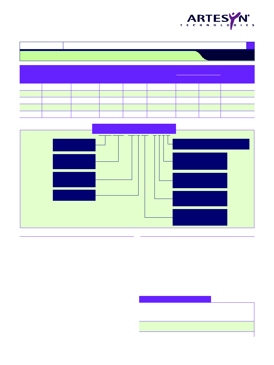
OUTPUT
INPUT
OUTPUT
OUTPUT
OUTPUT
EFFICIENCY
REGULATION
MODEL
POWER
VOLTAGE
VOLTAGE
CURRENT
CURRENT
(TYP.)
LINE
LOAD
NUMBER
(18,19)
(MAX.)
(MIN.)
(MAX.)
300 W
18-36 Vdc
7.2-13.2 Vdc
0 A
25 A
86%
±0.15%
±0.2%
RFB300-24S12Y
308 W
18-36 Vdc
16.8-29.4 Vdc
0 A
11 A
90%
±0.15%
±0.2%
RFB300-24S28Y
308 W
36-75 Vdc
16.8-29.4 Vdc
0 A
11 A
91%
±0.15%
±0.2%
RFB300-48S28Y
350 W
36-75 Vdc
7.2-13.2 Vdc
0 A
29.2 A
88%
±0.15%
±0.2%
RFB350-48S12Y
(17)
350 W
36-75 Vdc
16.8-29.4 Vdc
0 A
12.5 A
91%
±0.15%
±0.2%
RFB350-48S28Y
RoHS Compliance
(18)
Y = Non Pb-free (RoHS 5/6 compliant)
Number of Outputs
S = Single
Input Voltage
24 = 18 Vdc to 36 Vdc
48 = 36 Vdc to 75 Vdc
Rated Output Current
300 = 300/308 W
350 = 350 W
Product Family
RFB = Half-Brick
For the most current data and application support visit www.artesyn.com/powergroup/products.htm
DC-DC CONVERTERS 300-350 W Half-Brick
3
NEW Product
File Name: rfb300_350.pdf Rev: 03 Feb 2006
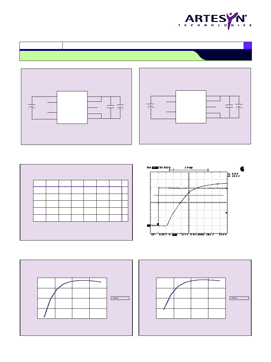
-Out
-Sen
+Out
Vadj
+Sen
+IN
-IN
Case
RC
1
µ
F
50 V
330
µ
F
330
µ
F
Figure 1 - Standard Application - 28 V Models
-Out
-Sen
+Out
Vadj
+Sen
+IN
-IN
Case
RC
1
µ
F
50 V
470
µ
F
330
µ
F
Figure 2 - Standard Application - 12 V Models
RFB300/350 Series
2 4 V i n a n d 4 8 V i n s i n g l e o u t p u t
O
U
T
P
U
T
C
U
R
R
E
N
T
M
A
X
.
(
%
)
TEMPERATURE (∫C) BASEPLATE
0
20
40
60
80
100
-40
-20
0
20
40
60
80
100
Figure 3 - Derating Curve - All Models
Figure 4 - Typical Turn-on Delay and Risetime RFB350-48S28Y
Channel 1: Output Voltage, Channel 2: Input Voltage
0
3
6
9
12
84
86
88
90
92
E
F
F
I
C
I
E
N
C
Y
(
%
)
OUTPUT CURRENT (A)
Vin = 48 V
Figure 6 - Typical Efficiency vs. Output Current ≠ RFB300-48S28Y
0
3
6
9
12
83
85
87
89
91
E
F
F
I
C
I
E
N
C
Y
(
%
)
OUTPUT CURRENT (A)
Vin = 24 V
Figure 5 - Typical Efficiency vs. Output Current ≠ RFB300-24S28Y
For the most current data and application support visit www.artesyn.com/powergroup/products.htm
DC-DC CONVERTERS 300-350 W Half-Brick
4
NEW Product
File Name: rfb300_350.pdf Rev: 03 Feb 2006
0
5
10
15
20
25
30
80
82
84
86
88
90
P
E
R
C
E
N
T
E
F
F
I
C
I
E
N
C
Y
(
%
)
OUTPUT CURRENT (A)
Vin = 24 V
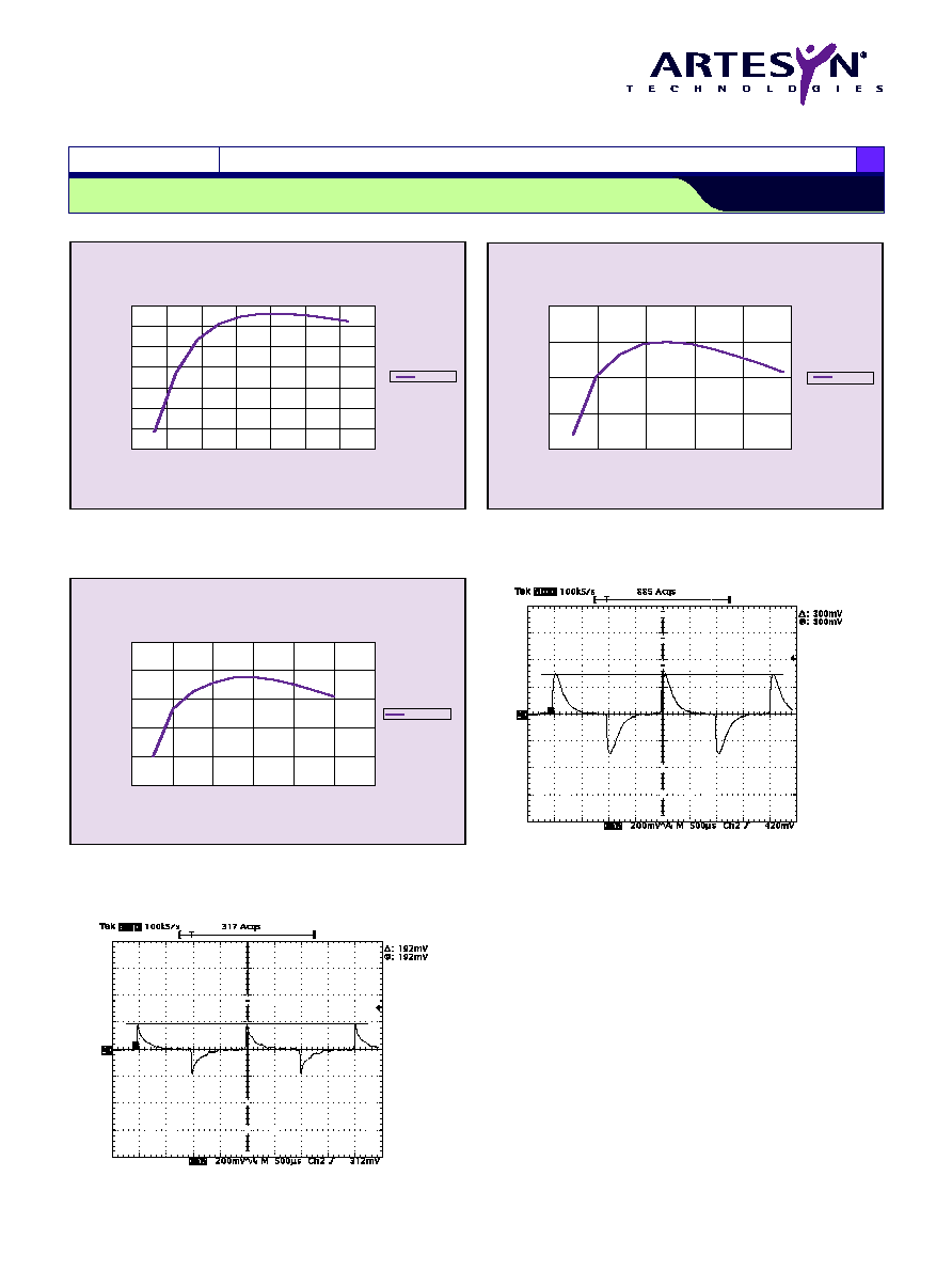
Figure 9 - Typical Efficiency vs. Output Current ≠ RFB300-24S12Y
RFB300/350 Series
2 4 V i n a n d 4 8 V i n s i n g l e o u t p u t
Figure 10 - RFB350-48S28Y Transient Response
Load 6.25-9.38 A
Figure 11 - RFB350-48S12Y Transient Response
Load 14.5-21.75 A
0
2
4
6
8
10
12
14
85
86
87
88
89
90
91
92
E
F
F
I
C
I
E
N
C
Y
(
%
)
OUTPUT CURRENT (A)
Vin = 48 V
Figure 7 - Typical Efficiency vs. Output Current ≠ RFB350-48S28Y
0
6
12
18
24
30
84
86
88
90
92
E
F
F
I
C
I
E
N
C
Y
(
%
)
OUTPUT CURRENT (A)
Vin = 48 V
Figure 8 - Typical Efficiency vs. Output Current ≠ RFB350-48S12Y
File Name: rfb300_350.pdf Rev: 03 Feb 2006
Please consult our website for the following items:
Application Note
www.artesyn.com
Datasheet © Artesyn TechnologiesÆ 2005
The information and specifications contained in this datasheet are believed to be correct at time of publication. However, Artesyn Technologies accepts no responsibility for consequences arising
from printing errors or inaccuracies. The information and specifications contained or described herein are subject to change in any manner at any time without notice. No rights under any patent
accompany the sale of any such product(s) or information contained herein.
For the most current data and application support visit www.artesyn.com/powergroup/products.htm
DC-DC CONVERTERS 300-350 W Half-Brick
5
NEW Product
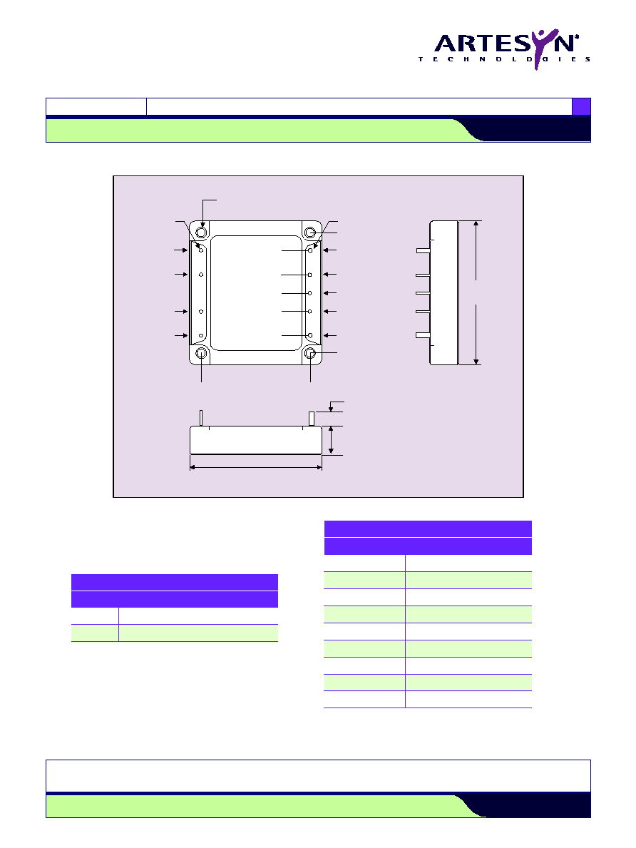
Figure 12 - Mechanical Drawing, Dimension Options and Pin-Out Table
RFB300/350 Series
2 4 V i n a n d 4 8 V i n s i n g l e o u t p u t
Case
-Vin
+Vin
RC
-Sen
Vadj
2x ¯0.081 (2.06)
7x ¯0.040 (1.02)
-Vout
+Vout
+Sen
0.23
±
0.02 (5.84
±
0.51)
0.00 (0.00)
1.900 (48.26)
0 (0.00)
2.000 (50.80)
0
2.27
±
0.02 (57.66
±
0.51)
Case Footprint
2.39
±
0.02
(60.71
±
0.51)
Case Footprint
Height
(See Dimension Option Table Below)
4 x Thru Hole Insert 0.128 (3.25) Clearance
(M3 x 0.5 Threaded Inserts are Available)
0.300 (7.62)
0.700 (17.78)
1.000 (25.40)
1.300 (33.02)
1.700 (43.18)
DIMENSION OPTIONS
OPTION
HEIGHT
5
0.50 ±0.02 (12.70 ±0.51)
4
0.40 ±0.02 (10.16 ±0.51)
PIN CONNECTIONS
PIN NUMBER
FUNCTION
-Vin
Negative Input Terminal
Case
RC
ON/OFF Control Terminal
+Vin
Positive Input Terminal
+Vout
Positive Output Terminal
+Sen
Positive Remote Sense
Vadj
Output Adjustment Trim Pin
-Sen
Negative Remote Sense
-Vout
Negative Output Terminal