 | –≠–ª–µ–∫—Ç—Ä–æ–Ω–Ω—ã–π –∫–æ–º–ø–æ–Ω–µ–Ω—Ç: SMT15F | –°–∫–∞—á–∞—Ç—å:  PDF PDF  ZIP ZIP |

DC-DC CONVERTERS Typhoon Non-isolated
1
NEW Product
File Name: smt15f_12_fixed.pdf Rev (02): 16 Dec 2005
International Safety Standard Approvals
UL/cUL CAN/CSA 22.2 No. E174104
UL 60950 File No. E174104
TÐV Product Service (EN60950) Certificate No. B 04 04 38572 041
CB report and certificate to IEC60950 DE3-52484
2 YEAR WARRANTY
All specifications are typical at nominal input, full load at 25 ∞C unless otherwise stated
C
in
= 270 µF, C
out
= 0 µF
SPECIFICATIONS
The SMT15F-12 series are non-isolated dc-dc converters packaged in a surface-mount footprint
giving designers a cost effective solution for conversion from a 12 V source. The SMT15F-12 has an
input range of 10.8 Vdc to 13.2 Vdc and offers an output voltage range from 1.0 Vdc to 1.8 Vdc with a
15 A load, which allows for maximum design flexibility and a pathway for future upgrades. The
SMT15F-12 is designed for applications that include distributed power, workstations, optical network
and wireless applications. Implemented using state of the art surface-mount technology and
automated manufacturing techniques, the SMT15F-12 offers compact size and efficiencies of up to
88% at 1.8 Vout.
∑
Designed to meet ultra fast transient
requirements: 300 A/µs step load transients
∑
15 A Current rating
∑
Input voltage range: 10.8 Vdc to 13.2 Vdc
∑
Output voltage range: 1.0 Vdc to 1.8 Vdc
∑
Extremely low internal power dissipation
∑
Minimal thermal design concerns
∑
Ideal solution where board space is at a premium
or tighter card pitch is required
∑
Industry standard surface-mount footprint
∑
Available RoHS compliant
SMT15F Series
1 2 V i n s i n g l e f i x e d o u t p u t
OUTPUT SPECIFICATIONS
Voltage adjustability
(Trimmable)
±10%
Setpoint accuracy
±2.5% typ.
Line regulation
±1.0% typ.
Load regulation
±1.0% typ.
Total error band
±3.0% typ.
Minimum load
0 A
Overshoot/undershoot
None
Ripple and noise
5 Hz to 20 MHz
40 mV pk-pk
25 mV rms
Temperature co-efficient
±0.01%/∫C
Transient response
di/dt 200 A/µs
7.5 A load step
(1.2 Vout)
(See Note 3)
50 mV max. deviation
<10 µs recovery to
within ±1.0%
Remote sense
10% Vo compensation
INPUT SPECIFICATIONS
Input voltage range
10.8 Vdc to 13.2 Vdc
Input current
No load
100 mA
Input current (max.)
2.0 A max. @ Io max.
and Vout = 1. 2 V
Input reflected ripple
100 mA rms
Remote ON/OFF
(See Note 1)
Start-up time
5 ms
EMC CHARACTERISTICS
Electrostatic discharge
EN61000-4-2, IEC801-2
Conducted immunity
EN61000-4-6
Radiated immunity
EN61000-4-3
GENERAL SPECIFICATIONS
Efficiency
Vin = 12 V, Vout = 1.8 V
88% typ.
Insulation voltage
Non-isolated
Switching frequency
Variable
700 kHz typ.
Vin = 12 V, Vout = 1.2 V
Approvals and
EN60950
standards
UL/cUL60950
Material flammability
UL94V-0
Dimensions
(LxWxH)
33.02 x 13.46 x 7.57 mm
1.3 x 0.53 x 0.298 inches
Weight
7 g (0.25 oz)
Coplanarity
100 µm
MTBF
Telcordia SR-332
16,529,000 hours
ENVIRONMENTAL SPECIFICATIONS
Thermal performance
Operating ambient,
-40 ∫C to +85 ∫C
(See Figure 1)
temperature
Non-operating
-40 ∫C to +125 ∫C
PROTECTION
Short-circuit Continuous
Thermal Automatic
recovery

File Name: smt15f_12_fixed.pdf Rev (02): 16 Dec 2005
For the most current data and application support visit www.artesyn.com/powergroup/products.htm
DC-DC CONVERTERS Typhoon Non-isolated
2
NEW Product
N
No
otte
es
s
1
The SMT15F-12 features an `Active High' Remote ON/OFF operation. If
not using the Remote ON/OFF pin, leave the pin open (the converter will
be on). The Remote ON/OFF pin is referenced to ground.
The following conditions apply for the SMT15F-12:
Configuration
Converter Operation
Remote pin open circuit
Unit is ON
Remote pin pulled low
Unit is OFF
Remote pin pulled high
Unit is ON
An `Active Low' Remote ON/OFF version is also possible with this
converter. To order please place the Suffix `R' towards the end of the part
number, e.g. SMT15F-12S1V8RJ.
2
A 270 µF electrolytic input capacitor maybe required for test purposes
only.
3
An external output capacitor is not required for basic operation. Adding
distributed capacitance at the load will improve the transient response.
4
TSE RoHS 5/6 (non Pb-free) compliant versions may be available on
special request, please contact your local sales representative for details.
5
NOTICE: Some models do not support all options. Please contact your
local Artesyn representative or use the on-line model number search tool
at http://www.artesyn.com/powergroup/products.htm to find a suitable
alternative.
SMT15F Series
1 2 V i n s i n g l e f i x e d o u t p u t
S M T 1 5 F - 1 2 S 1 V 2 J
Part Number System with Options
Product Family
SMT = Surface Mount
Rated Output Current
15 = 15 Amps
Input Voltage
12 = 10.8 Vdc to 13.2 Vdc
Type of Output
S = Single
W = Fixed
Performance
F = Enhanced/Fast Transient
Performance
Output Voltage
1V0 = 1.0 V, 1V2 = 1.2 V etc.
OUTPUT
INPUT
OUTPUT
OUTPUT
OUTPUT
EFFICIENCY
REGULATION
MODEL
POWER
VOLTAGE
VOLTAGE
CURRENT
CURRENT
(TYP.)
LINE
LOAD
NUMBER
(1,4,5)
(MAX.)
(MIN.)
(MAX.)
15.0 W
10.8-13.2 Vdc
1 Vdc
0 A
15 A
85%
±1.0%
±1.0%
SMT15F-12S1V0J
18.0 W
10.8-13.2 Vdc
1.2 Vdc
0 A
15 A
86%
±1.0%
±1.0%
SMT15F-12S1V2J
22.5 W
10.8-13.2 Vdc
1.5 Vdc
0 A
15 A
87%
±1.0%
±1.0%
SMT15F-12S1V5J
27.0 W
10.8-13.2 Vdc
1.8 Vdc
0 A
15 A
88%
±1.0%
±1.0%
SMT15F-12S1V8J
Packaging Options
(4)
J = Pb-free (RoHS 6/6 compliant)
For the most current data and application support visit www.artesyn.com/powergroup/products.htm
DC-DC CONVERTERS Typhoon Non-isolated
3
NEW Product
File Name: smt15f_12_fixed.pdf Rev (02): 16 Dec 2005
0
10
20
30
40
50
70
0
6
8
10
OUTPUT CURRENT (A)
Nat conv
200 LFM
400 LFM
80
16
12
TEMPERATURE (∫C)
4
2
60
14
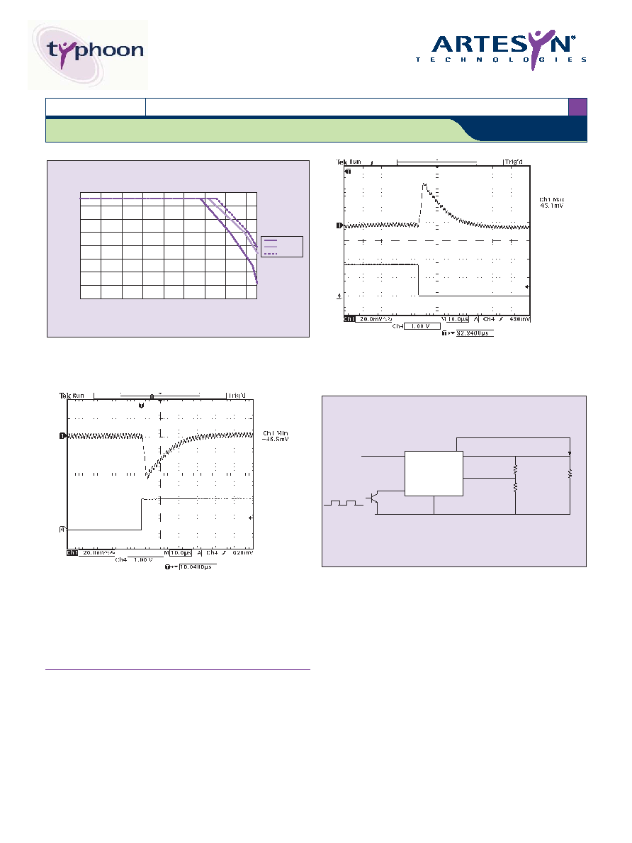
Figure 1 - Derating Curve
Vin = 12 V, Output Voltage = 1.2 V (See Note A)
Figure 2 - Typical Transient Response,
(Vin = 12 V, Output Current = 1.2 V),
7.5 A Load Step Change; Slew Rate = 200 A/µs
Channel 1: Voltage Deviation = 45 mV; Recovery Time = 10 µs
N
No
otte
es
s
A
The derating curve represents the conditions at which internal
components are within the Artesyn derating guidelines.
SMT15F Series
1 2 V i n s i n g l e f i x e d o u t p u t
Vout
R Load
Vin
SMT15F
Common
ON/OFF
Trim pin
Rtrimdown
Rtrimup
+Vsense
Figure 4 - Standard Application
Figure 3 - Typical Transient Response,
(Vin = 12 V, Output Current = 1.2 V),
7.5 A Load Step Change; Slew Rate = 200 A/µs
Channel 1: Voltage Deviation = 46.8 mV; Recovery Time = 10 µs

File Name: smt15f_12_fixed.pdf Rev (02): 16 Dec 2005
Please consult our website for the following items:
Application Note
www.artesyn.com
Datasheet © Artesyn TechnologiesÆ 2005
The information and specifications contained in this datasheet are believed to be correct at time of publication. However, Artesyn Technologies accepts no responsibility for consequences arising
from printing errors or inaccuracies. The information and specifications contained or described herein are subject to change in any manner at any time without notice. No rights under any patent
accompany the sale of any such product(s) or information contained herein.
For the most current data and application support visit www.artesyn.com/powergroup/products.htm
DC-DC CONVERTERS Typhoon Non-isolated
4
NEW Product
Figure 5 - Mechanical Drawing and Pinout Table
SMT15F Series
1 2 V i n s i n g l e f i x e d o u t p u t
SIDE VIEW
Connector (6PL)
Width: 0.112
± 0.003 (2.84 ± 0.08)
Length: 0.062
± 0.002 (1.57 ± 0.04)
All dimensions in inches (mm)
All tolerance
±0.010in (±0.25mm)
unless otherwise stated
0.298 (7.57)
Installed Ht.
BOTTOM VIEW
0.190
(4.83)
0.190
(4.83)
0.190
(4.83)
0.310
(7.87)
0.430 (10.92)
0.048 (1.22)
0.075 (1.91)
0.405 (10.29)
0.297
(7.54)
Remote
ON/OFF
+Vin
GND
Vout
Trim
Sense
1.300
±0.010 (33.02 ±0.25)
0.039 (1.00)
0.530
±0.010
(13.46
± 0.25)
0.039 (1.00)
TOP VIEW
Seating Plane
PIN CONNECTIONS
PIN NUMBER
FUNCTION
1
+Vin
2
GND
3
+Vout
4
Trim
5
+Vsense
6
Remote ON/OFF