
Siemens AG
9
Solid State Relays (SSR)
V23100-S
V23107-S
Features
q
Fully electronic semi-conductor relays
q
High switching speed and endurance
q
Switch-on at voltage zero crossing, with relays with zero
voltage switch
q
Switch-off in current zero crossing
q
Silent switching
q
Spark- and bounce-free switching
q
Electrical isolation between control circuit and switching
circuit
q
Low control power
q
Logic compatibility (TTL)
q
Not sensitive to vibration, impact or extreme environmen-
tal conditions
Typical applications
q
Heating control systems
q
Ovens and cookers
q
Photocopying machines
q
High performance laser printers
q
Medical equipment
q
Industrial controls
q
Traffic signaling systems
Design
≠
With or without zero voltage switch
≠
One- and three-phase relay types
≠
Switching circuit: triac or 2 anti-parallel thyristors;
corresponds to one make contact
≠
Terminal type: PCB and screw
≠
Plastic coating
≠
Dust-protected (V23100-S... Type C2) or immersion
cleanable
Approvals
VDE
Marks of conformity
and
UL
ML File E 85134 and
ML File E48393
VDE
79102
86713
10
Siemens AG
Solid State Relays (SSR)
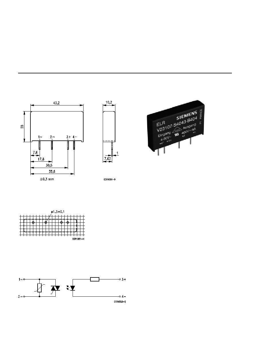
Type B404
Dimension drawing (mm)
Mounting hole layout
View on the terminals
Basic grid dimension 2.54 mm in accordance with EN 60097
Illustration approximately same size as original
Terminal assignment
Simplified circuit diagram
Tolerances
ECR0980-B
Siemens AG
11
Solid State Relays (SSR)
Type B404
SSR with zero voltage switch for PCB mounting
Ordering code
V23107
-S4022-B404
-S4023-B404
-S4042-B404
-S4043-B404
Control circuit
(typical values at 20 ∞C)
Minimum control voltage
2.5 V
-
4 V
-
Maximum control voltage
10 V
-
30 V
-
Minimum control current
3 mA
-
Maximum control current
30 mA
-
Release voltage
0.8 V
-
Control circuit resistance
330
1,000
Switching circuit
(typical values at 20 ∞C)
Maximum switching current
(see characteristic page 13)
4 A
rms
Minimum switching current
5 mA
rms
Nominal switching voltage
230 V
rms
400 V
rms
230 V
rms
400 V
rms
Switching voltage range
12...275 V
rms
12...460 V
rms
12...275 V
rms
12...460 V
rms
Maximum repetitive blocking voltage
(Voltage limited by varistor)
600 V
S
(450 V
S
)
1,000 V
S
(720 V
S
)
600 V
S
(450 V
S
)
1,000 V
S
(720 V
S
)
Zero voltage range
±
12 V
S
Maximum surge current (ITSM, 10 ms)
(see surge current gradient page 13)
100 A
S
Leakage current at nominal switching voltage
(50 Hz)
0.3 mA
rms
Peak load integral (I
2
t, 10 ms)
50 A
2
s
Critical rate of rise on-state current (di/dt)
20 A/
µ
s
Critical rate of rise off-state voltage (du/dt)
500 V/
µ
s
Max. on-state voltage at max. switching
current
1.6 V
S
Operating frequency range
10...440 Hz
Maximum on- and off-time (50 Hz)
10 ms
Insulation
Test voltage between control circuit and
switching circuit
4 kV
rms
General data
Operating temperature range
-
40...+80 ∞C
Storage temperature range
-
40...+150 ∞C
Capacity between control circuit and switching
circuit
8 pF
Weight
approx. 20 g
Approvals
VDE, UL
N.B.: Clearances and creepage distances in accordance with EN 60950:1992+A1/DIN EN 60950 (VDE 0805):11.93

12
Siemens AG
Solid State Relays (SSR)
Type B404
SSR without zero voltage switch for PCB mounting
Ordering code
V23107
-S4342-B404
-S4343-B404
Control circuit
(typical values at 20 ∞C)
Minimum control voltage
3 V
-
Maximum control voltage
30 V
-
Minimum control current
2 mA
-
Maximum control current
30 mA
-
Release voltage
0.8 V
-
Control circuit resistance
1,000
Switching circuit
(typical values at 20 ∞C)
Max. switching current
(see characteristic page 13)
4 A
rms
Minimum switching current
5 mA
rms
Nominal switching voltage
230 V
rms
400 V
rms
Switching voltage range
12...275 V
rms
12...460 V
rms
Maximum repetitive blocking voltage
(voltage limited by varistor)
600 V
S
(450 V
S
)
1,000 V
S
(720 V
S
)
Maximum surge current (ITSM, 10 ms)
(see surge current gradient page 13)
100 A
S
Leakage current at nominal switching voltage
(50 Hz)
0.3 mA
rms
Peak load integral (I
2
t, 10 ms)
50 A
2
s
Critical rate of rise on-state current (di/dt)
20 A/
µ
s
Critical rate of rise off-state voltage (du/dt)
500 V/
µ
s
Max. on-state voltage at max.
switching current
1.6 V
S
Operating frequency range
10...440 Hz
Maximum on time
0.1 ms
Maximum off time
10 ms
Insulation
Test voltage between control circuit and
switching circuit
4 kV
rms
General data
Operating temperature range
-
40...+80 ∞C
Storage temperature range
-
40...+150 ∞C
Capacity between control circuit and switching
circuit
8 pF
Weight
approx. 20 g
Approvals
VDE, UL
N.B.: Clearances and creepage distances in accordance with EN 60950:1992+A1/DIN EN 60950 (VDE 0805):11.93

Siemens AG
13
Solid State Relays (SSR)
Type B404
Maximum accidental overload current (not periodical): ITSM
Max. switching current depending on ambient temperature
Surge
c
u
rren
t
[A]
Number of periods
Swit
c
h
ing
c
u
rren
t
[A
rms
]
Ambient temperature [
∞
C]
Control voltage
<
10 V
Control voltage
>
10 V