 | –≠–ª–µ–∫—Ç—Ä–æ–Ω–Ω—ã–π –∫–æ–º–ø–æ–Ω–µ–Ω—Ç: AAT1231 | –°–∫–∞—á–∞—Ç—å:  PDF PDF  ZIP ZIP |

General Description
The AAT1231/1231-1 are high frequency, high effi-
ciency constant current boost converters capable of
24V maximum output voltage. Both devices are
ideal power solutions for backlight applications with
up to six white LEDs in series or up to twelve white
LEDs in a parallel/series configuration. The input
voltage is 2.7V to 5.5V for single-cell lithium-
ion/polymer (Li-ion) based portable devices.
The LED current is digitally controlled across a 6x
operating range using AnalogicTech's Simple Serial
ControlTM (S
2
CwireTM) interface. Programmability
across 26 discrete current steps provides high reso-
lution, low noise, flicker-free, constant LED outputs.
In programming AAT1231 operation, LED brightness
increases based on the data received at the EN/SET
pin. In programming AAT1231-1 operation, LED
brightness decreases based on the data received at
the EN/SET pin. The SEL logic pin changes the feed-
back voltage between two programmable ranges.
The AAT1231 and the AAT1231-1 feature high current
limit and fast, stable transitions for stepped or pulsed
current applications. The high switching frequency (up
to 2MHz) provides fast response and allows the use
of ultra-small external components, including chip
inductors and capacitors. Fully integrated control cir-
cuitry simplifies design and reduces total solution size.
The AAT1231 and the AAT1231-1 offer a true load
disconnect feature which isolates the load from the
power source while in the OFF or disabled state. This
eliminates leakage current, making the devices ideal-
ly suited for battery-powered applications.
The AAT1231 and the AAT1231-1 are available in Pb-
free, thermally-enhanced 12-pin TSOPJW packages.
Features
∑
Input Voltage Range: 2.7V to 5.5V
∑
Maximum Continuous Output 24V @ 50mA
∑
Drives 6 LEDs in Series, 12 LEDs in Parallel/
Series Configuration
-- Constant LED Current with 6% Accuracy
∑
Digital Control with S
2
Cwire Single Wire Interface
-- 26 Discrete Steps
-- No PWM Control Required
-- No Additional Circuitry
∑
Up to 82% Efficiency
∑
Up to 2MHz Switching Frequency Allows
Small External Chip Inductor and Capacitors
∑
Hysteretic Control
-- No External Compensation Components
-- Excellent Load Transient Response
-- High Efficiency at Light Loads
∑
Integrated Soft Start with No External Capacitor
∑
True Load Disconnect Guarantees <1.0µA
Shutdown Current
∑
Selectable Feedback Voltage Ranges for
High Resolution Control of Load Current
∑
Short-Circuit, Over-Voltage, and Over-
Temperature Protection
∑
12-Pin TSOPJW Package
∑
-40∞C to +85∞C Temperature Range
Applications
∑
Digital Still Cameras (DSCs)
∑
Mobile Handsets
∑
MP3 Players
∑
PDAs and Notebook PCs
∑
White LED Drivers
AAT1231/1231-1
Step-Up DC/DC Converters for
White LED Backlight Applications
Typical Application
LIN
C
2
2.2µF
R
2
226k
R
3
12k
R
1
(R
BALLAST
)
30.1
C
1
2.2µF
L = 2.2µH
DS1
Capable of Driving
Six LEDs in Series
(see Applications Section)
OSRAM
LW M678
EN/SET
PGND
PVIN
AAT1231/
1231-1
SW
FB
SEL
Up to 24V/
50mA max
VIN
AGND
OVP
Li-Ion:
V
IN
= 2.7V to 4.2V
Enable/Set
Select
1231.2006.08.1.1
1
SwitchReg
TM

Pin Descriptions
Pin Configuration
TSOPJW-12
(Top View)
1
2
3
4
5
6
12
11
10
9
8
7
PVIN
EN/SET
SEL
VIN
N/C
SW
LIN
OVP
FB
AGND
PGND
SW
Pin #
Symbol
Function
1
PVIN
Input power pin; connected to the source of the P-channel MOSFET. Connect to the
input capacitor(s).
2
EN/SET
IC enable pin and S
2
Cwire input control to set output current.
3
SEL
FB voltage range select.
For the AAT1231, a logic LOW sets the FB voltage range from 0.1V to 0.4V; a logic
HIGH sets the FB voltage range from 0.3V to 0.6V.
For the AAT1231-1, a logic LOW sets the FB voltage range from 0.4V to 0.1V; a logic
HIGH sets the FB voltage range from 0.6V to 0.3V.
4
VIN
Input voltage for the converter. Connect directly to the PVIN pin.
5
N/C
No connection.
6, 7
SW
Boost converter switching node. Connect the power inductor between this pin and LIN.
8
PGND
Power ground for the boost converter.
9
AGND
Ground pin.
10
FB
Feedback pin. Connect a resistor to ground to set the maximum LED current.
11
OVP
Feedback pin for over-voltage protection sense.
12
LIN
Switched power input. Connect the power inductor between this pin and SW.
AAT1231/1231-1
Step-Up DC/DC Converters for
White LED Backlight Applications
2
1231.2006.08.1.1
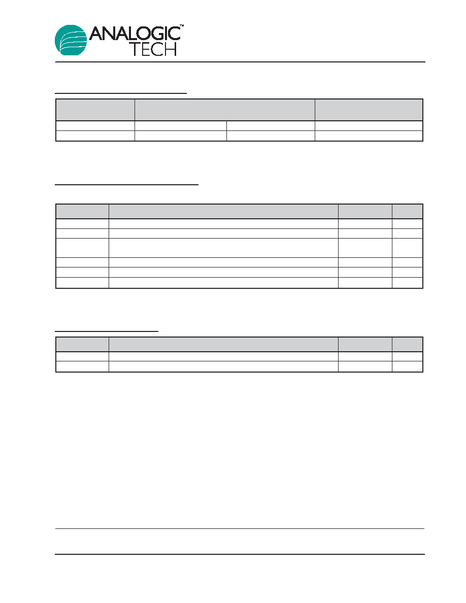
Part Number Descriptions
Absolute Maximum Ratings
1
T
A
= 25∞C unless otherwise noted.
Thermal Information
Symbol
Description
Value
Units
JA
Thermal Resistance
160
∞C/W
P
D
Maximum Power Dissipation
625
mW
Symbol
Description
Value
Units
PVIN, VIN
Input Voltage
-0.3 to 6.0
V
SW
Switching Node
28
V
LIN, EN/SET,
Maximum Rating
V
IN
+ 0.3
V
SEL, FB
T
J
Operating Temperature Range
-40 to 150
∞C
T
S
Storage Temperature Range
-65 to 150
∞C
T
LEAD
Maximum Soldering Temperature (at leads, 10 sec)
300
∞C
SEL Polarity
S
2
C Feedback
Part Number
HIGH
LOW
Voltage Programming
AAT1231ITP
0.3V
V
FB
0.6V
0.1V
V
FB
0.4V
See Table 2
AAT1231ITP-1
0.6V
V
FB
0.3V
0.4V
V
FB
0.1V
See Table 3
AAT1231/1231-1
Step-Up DC/DC Converters for
White LED Backlight Applications
1231.2006.08.1.1
3
1. Stresses above those listed in Absolute Maximum Ratings may cause permanent damage to the device. Functional operation at condi-
tions other than the operating conditions specified is not implied. Only one Absolute Maximum Rating should be applied at any one time.

Electrical Characteristics
1
T
A
= -40∞C to +85∞C unless otherwise noted. Typical values are at 25∞C, V
IN
= 3.6V.
Symbol
Description
Conditions
Min
Typ
Max
Units
Power Supply
PV
IN
, V
IN
Input Voltage Range
2.7
5.5
V
V
OUT(MAX)
Maximum Output Voltage
24
V
I
Q
Operating Current
SEL = GND, FB = 0.1V
40
70
µA
I
SHDN
Shutdown Current
EN/SET = GND
1.0
µA
I
OUT
Maximum Continuous Output
2.7V < V
IN
< 5.5V, V
OUT
= 24V
50
mA
Current
2
V
LINEREG(FB)
/
Line Regulation
V
IN
= 2.7V to 5.5V, V
FB
= 0.6V
0.7
%/V
V
IN
R
DS(ON) L
Low Side Switch On Resistance
80
m
R
DS(ON) IN
Input Disconnect Switch
180
m
On Resistance
T
SS
Soft-Start Time
From Enable to Output Regulation;
300
µs
V
FB
= 300mV
V
OVP
Over-Voltage Protection Threshold V
OUT
Rising
1.1
1.2
1.3
V
Over-Voltage Hysteresis
V
OUT
Falling
100
mV
I
LIMIT
N-Channel Current Limit
2.5
A
T
SD
T
J
Thermal Shutdown Threshold
140
∞C
T
HYS
T
J
Thermal Shutdown Hysteresis
15
∞C
SEL, EN/SET
V
SEL(L)
SEL Threshold Low
0.4
V
V
SEL(H)
SEL Threshold High
1.4
V
V
EN/SET(L)
Enable Threshold Low
0.4
V
V
EN/SET(H)
Enable Threshold High
1.4
V
T
EN/SET (LO)
EN/SET Low Time
V
EN/SET
< 0.6V
0.3
75
µs
T
EN/SET(HI)
EN/SET High Time
V
EN/SET
> 1.4V
50
75
ns
T
OFF
EN/SET Off Timeout
V
EN/SET
< 0.6V
500
µs
T
LAT
EN/SET Latch Timeout
V
EN/SET
> 1.4V
500
µs
I
EN/SET
EN/SET Input Leakage
V
EN/SET
= 5V V
IN
= 5V
-1
1
µA
AAT1231
V
IN
= 2.7V to 5.5V, SEL = GND,
0.09
0.1
0.11
FB
FB Pin Regulation
EN/SET = HIGH
V
V
IN
= 2.7V to 5.5V, SEL = HIGH,
0.564
0.6
0.636
EN/SET = DATA16
AAT1231-1
V
IN
= 2.7V to 5.5V, SEL = GND,
0.09
0.1
0.11
FB
FB Pin Regulation
EN/SET = DATA16
V
V
IN
= 2.7V to 5.5V, SEL = HIGH,
0.564
0.6
0.636
EN/SET = HIGH
AAT1231/1231-1
Step-Up DC/DC Converters for
White LED Backlight Applications
4
1231.2006.08.1.1
1. Specification over the -40∞C to +85∞C operating temperature range is assured by design, characterization, and correlation with statis-
tical process controls.
2. Maximum continuous output current increases with reduced output voltage, but may vary depending on operating efficiency and ther-
mal limitations.

Typical Characteristics
Feedback Voltage vs. Temperature
(R
BALLAST
= 30.1
)
Temperature (
∞C)
Feedback Voltage (mV)
0
100
200
300
400
500
600
700
-40
-15
10
35
60
85
Shutdown Current vs. Input Voltage
(EN = GND)
Input Voltage (V)
Shutdown Current (µA)
0.0
0.2
0.4
0.6
0.8
1.0
2.7
3.1
3.5
3.9
4.3
4.7
5.1
5.5
-40∞C
85∞C
25∞C
Efficiency vs. LED Current
(12 White LEDs; R
BALLAST
= 30.1
)
LED Current (mA)
Efficiency (%)
74
75
76
77
78
79
80
81
82
83
84
2
4
6
8
10
12
14
16
18
20
V
IN
= 3.6V
V
IN
= 4.2V
V
IN
= 5V
Efficiency vs. LED Current
(6 White LEDs; R
BALLAST
= 30.1
)
LED Current (mA)
Efficiency (%)
73
74
75
76
77
78
79
80
81
2
4
6
8
10
12
14
16
18
20
V
IN
= 3.6V
V
IN
= 4.2V
V
IN
= 5V
Efficiency vs. LED Current
(5 White LEDs; R
BALLAST
= 30.1
)
LED Current (mA)
Efficiency (%)
75
76
77
78
79
80
81
82
83
2
4
6
8
10
12
14
16
18
20
V
IN
= 3.6V
V
IN
= 4.2V
V
IN
= 5V
Efficiency vs. LED Current
(4 White LEDs; R
BALLAST
= 30.1
)
LED Current (mA)
Efficiency (%)
77
78
79
80
81
82
83
84
85
2
4
6
8
10
12
14
16
18
20
V
IN
= 3.6V
V
IN
= 4.2V
V
IN
= 5V
AAT1231/1231-1
Step-Up DC/DC Converters for
White LED Backlight Applications
1231.2006.08.1.1
5