North America (USA): 1-888-41-ASTEC
Europe (UK): 44 (1384) 842-211
Asia (HK): 852-2437-9662
4
Special Features
Electrical Specs
20 Watts
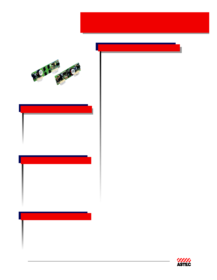
APA06
APA04 - Boost
∑ Excellent for POL Applications
∑ High Efficiency - Non Isolated
∑ 3.3V and 5V input,
∑ Standard SIP package 2.5 X .55 X .31"
∑ Enable and Trim Function
∑ Overcurrent Protection
∑ Sense Pins
Input
Input range
3.0 to 5.5V (Buck)
3.0 to 4.0V (Boost)
Efficiency
90% (5/3.3) , 83% (1.8V)
Output
Voltage tolerance
± 1.0%
Line regulation
± 0.5%
Load regulation
± 0.5%
Noise/ripple 50mV
P-P
Short circuit protection
Auto-recovery
Transient response
4%Vo, 200us
Temperature Regulation
±0.02 %Vo/∞C
Switching frequency
430kHz typ
Temperature coefficient
± 0.03%Vo/∞ C
Isolation
Non Isolated
Total Power:
20 Watts
Input Voltages: 3.3V, 5V
No. of Outputs: Single
Operating ambient temperature: -
25∞C to 55∞C (full load, 200LFM)
Storage temperature: -40∞C to +125∞C
MTBF: =7,000,000 hours (Bellcore TR332,
Ta=25∞C)
Weight: = 7.5 grams max
UL
UL 1950 Recognized
CSA
CAN22.2-950 Recognized
TUV
EN60950 Certified
Environmental
Safety
rev 01.14.03
EUROPE
Astec House, Waterfront Business Park
Merry Hill, Dudley
West Midlands, DY5 1LX, UK
Telephone: 44 (1384) 842-211
Facsimile: 44 (1384) 843-355
AMERICAS
5810 Van Allen Way
Carlsbad, CA 92008
Telephone: 760-930-4600
Facsimile: 760-930-0698
5
Ordering Information
www.astec.com
ASIA
Units 2111-2116, Level 21
Tower1, Metroplaza
223, Hing Fong Road
Fwai Fong, New Territories
Hong Kong
Telephone: 852-2437-9662
Facsimile: 852-2402-4426
Input
Output
Efficiency
Model Number
Voltage
Voltage
Buck
3.0-5.5 V
1.2V @ 6.0 A
80%
APA06K04
3.0-5.5 V
1.5V @ 6.0 A
81%
APA06M04
3.0-5.5 V
1.8V @ 6.0 A
83%
APA06Y04
3.0-5.5 V
2.1V @ 6.0 A
86%
APA06D04
4.5-5.5 V
2.5V @ 6.0 A
87%
APA06G05
4.5-5.5 V
3.3V @ 6.0 A
90%
APA06F05
Boost
3.3-4.0 V
5.0V @ 4.0 A
89%
APA04A03
Notes:
1. Add -E to eliminate Sense and Power Good feature
2. Right Angle Pins Available
Notes:
1. Recommended Input Filter - 220uF Electrolytic Cap
in parallel with 2.2uF Ceramic Cap Vin+ to GND
2. Recommended Output Filter - 2.2uF Ceramic Cap in
parallel with 1000uF Electrolytic Cap (Vout+ to GND)
3. 20 MHz bandwidth. An external 0.1 uf ceramic capacitor
is recommended to be placed from +V out to comm.
4. All specifications are typical at nominal line, full load,
and 25∞C unless otherwise noted.
5. All specifications subject to change without notice.
6. Mechanical drawings are for reference only.
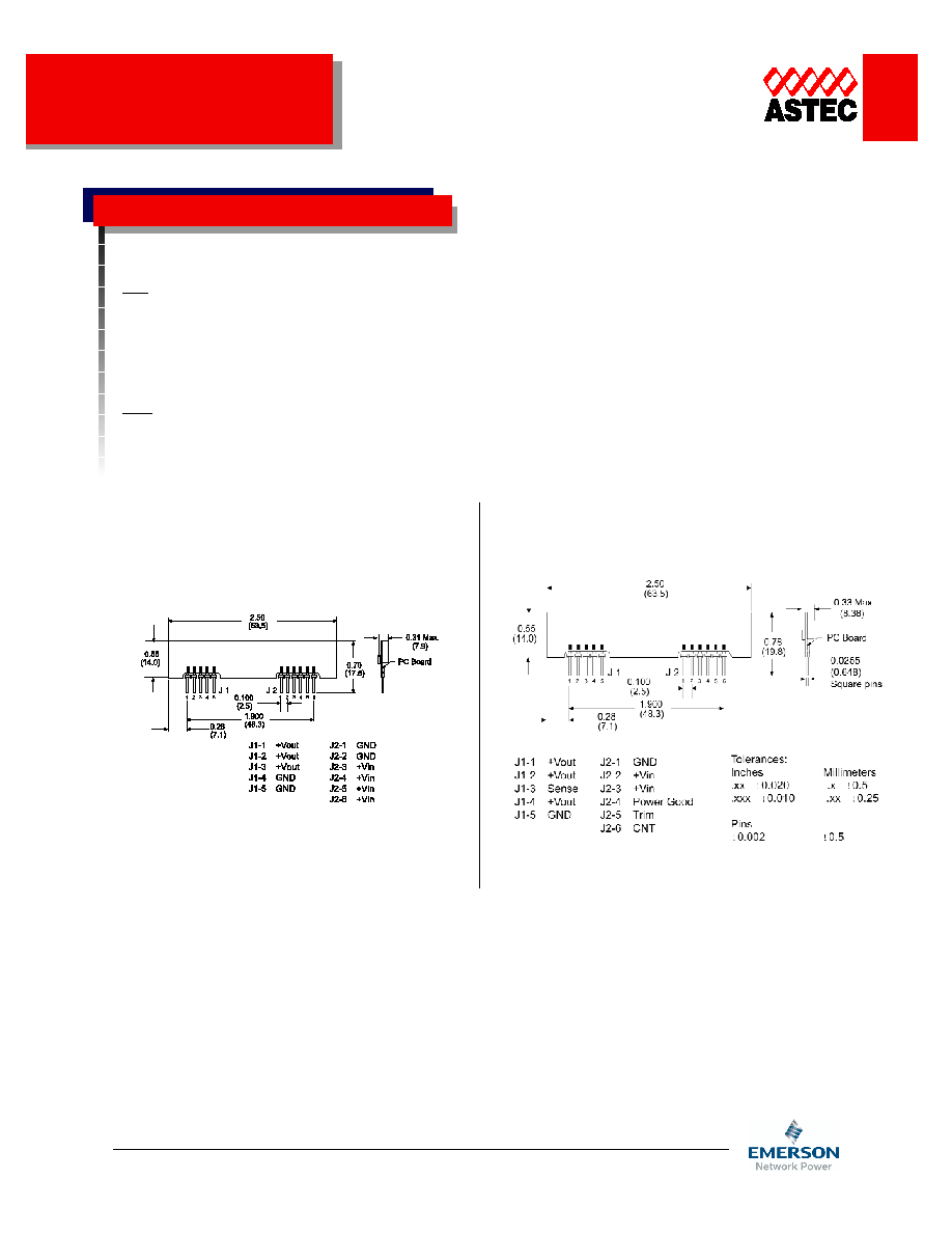
APA06/04
APA06 ( Buck ) Pinout
APA04 ( Boost ) Pinout