
1
Features
∑
Facilitates Development of Embedded Microcontroller Products with One or More
CPUs or Signal Processors
∑
Minimizes the Silicon Infrastructure Required to Support Efficient On-chip and Off-chip
Communication for Both Operation and Manufacturing Test
∑
Independent of a Specific Technology
∑
Ensures that Highly Reusable Peripheral and System Macrocells can be Migrated
across a Diverse Range of IC Processes and are Appropriate for Full-custom,
Standard-cell and Gate Array Technologies
∑
Encourages Modular System Design to Improve Processor Independence, Providing a
Development Roadmap for Advanced Cached CPU Cores and the Development of
Peripheral Libraries
∑
Use of Multiplexed Buses Facilitates Management of Data Buses and Provides
Improved Testability
Description
The system architecture derived from the specification for the Advanced Microcontrol-
ler Bus Architecture, AMBA
TM
, defines an on-chip communications standard for
designing high-performance 32-bit and 16-bit embedded microcontroller-based
systems.
Two distinct buses are defined within the AMBA specification:
∑
the Advanced System Bus (ASB) for high-performance system modules
∑
the Advanced Peripheral Bus (APB) for low-power peripherals
ASB supports the efficient connection of processors, on-chip memories and off-chip
external memory interfaces with low-power peripheral macrocell functions. The bus
also provides the test infrastructure for modular macrocell test and diagnostic access.
APB is optimized for minimal power consumption and reduced interface complexity to
support peripheral functions.
The ARM
Æ
AMBA specification, from which this document is derived, may be con-
sulted under the reference ARM IHI0001D, dated April 1997.
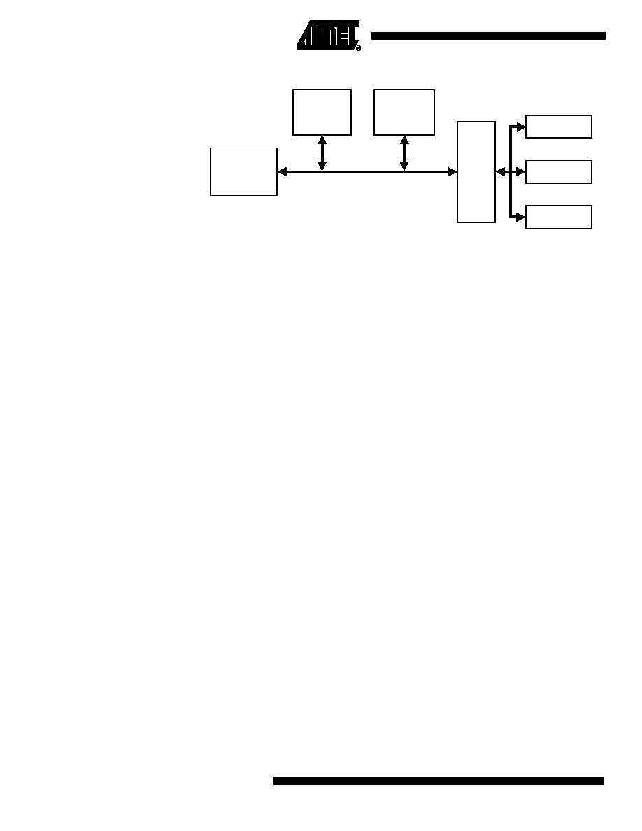
A Typical AMBA-based Microcontroller
An AMBA-based microcontroller typically consists of a high-performance system
backbone bus, able to sustain the external memory bandwidth, on which the CPU and
other direct memory access devices reside, plus a bridge to a narrower APB bus on
which the lower bandwidth peripheral devices are located.
ARM7TDMI
TM
-
based
Microcontroller
System
Architecture
Rev. 1353C≠CASIC≠02/02
2
System Architecture
1353C≠CASIC≠02/02
Figure 1. A Typical AMBA System
Terminology
The following terms are used throughout this specification.
Bus Cycle ≠ A bus cycle is a basic unit of one bus clock period and for the purpose of
protocol descriptions, is defined from falling-edge to falling-edge transitions. Bus signal
timing is referenced to the bus cycle clock.
Bus Transfer ≠ A bus transfer is a read or write operation of a data object, which may
take one or more bus cycles. The bus transfer is terminated by a "completion" response
from the addressed slave.
The transfer sizes supported include byte (8-bit), half-word (16-bit) and word (32-bit)
with a reserved code for future extension.
Bus Master ≠ A bus master is a system module that is able to initiate read and write
operations by providing an address and control information. Only one bus master is
allowed to actively use the bus at any one time.
Bus Slave ≠ A bus slave is a system module that responds to a read or write operation
within a given address≠space range. The bus slave signals back to the active master
the success, failure or extension of the data transfer.
Bus Arbiter ≠ The bus arbiter is a module that ensures that only one bus master at a
time is allowed to initiate data transfers. The arbitration scheme is not enforced such
that "highest priority" or "fair" access algorithms may be implemented, depending on the
application requirements.
Bus Decoder ≠ The bus decoder is a module that performs the decoding of the transfer
addresses and selects slaves appropriately. The bus decoder also ensures that the bus
remains operational when no bus transfers are required.
Burst Operation ≠ A burst operation is defined as one or more data transactions initi-
ated by a bus master, which have a consistent width of transaction to an incremental
region of address space. The increment step per transaction is determined by the width
of transfer (byte, half-word or word).
Bursts may be of arbitrary length and can be broken down into smaller packets by bus
slaves, which may not be able to accept burst operations, either over a particular
address boundary or over a particular burst length.
Advanced System Bus
Advanced
Peripheral Bus
External Bus
Interface
ARM
Processor
On-chip
RAM
Bridge
UART
Timer
PIO

3
System Architecture
1353C≠CASIC≠02/02
Signal Prefixes
This section contains a brief description of the signals associated with an AMBA-based
system and a full description of each of the signals may be found in later sections of this
document.
The first letter of the signal name is used to indicate the signal connectivity:
A= unidirectional signal between bus masters
and the arbiter
B = ASB signal
D = unidirectional signal from the bus decoder
P = APB signal
Signal List
Table 1. Signal List
Name
Description
AGNTx
Bus Grant. A signal from the bus arbiter to a bus master "x", which indicates that the bus master will be
granted the bus when BWAIT is low. There is an AGNTx signal for each bus master in the system, as well
as an associated bus request signal, AREQx.
AREQx
Bus Request. A signal from bus master "x" to the bus arbiter, which indicates that the bus master requires
the bus. There is an AREQx signal for each bus master in the system, as well as an associated bus grant
signal, AGNTx.
BA[31:0]
Address Bus. The system address bus, which is driven by the active bus master.
BCLK
Bus Clock. This clock times all bus transfers. Both the low phase and high phase of BCLK are used to
control transfers on the bus.
BRDATA[31:0]
ASB Read Data Bus. This is the system read data bus. The read data bus is driven by the selected bus
slave during read transfers.
BWDATA[31:0]
ASB Write Data Bus. This is the system write data bus. The write data bus is driven by the current bus
master during write transfers.
BERROR
Error Response. A transfer error is indicated by the selected bus slave using the BERROR signal. When
BERROR is high, a transfer error has occurred; when BERROR is low, then the transfer is successful. This
signal is also used in combination with the BLAST signal to indicate a bus retract operation.
When no slave is selected, this signal is driven by the bus decoder.
BLAST
Last Response. This signal is driven by the selected bus slave to indicate if the current transfer should be
the last of a burst sequence. When BLAST is high, the decoder must allow sufficient time for address
decoding. When BLAST is low, the next transfer may continue a burst sequence. This signal is also used in
combination with the BERROR signal to indicate a bus retract operation.
When no slave is selected, this signal is driven by the bus decoder.
BLOKx
Locked Transfers. An active high signal from the bus master "x" to the arbiter indicates that the current
transfer and the next transfer are to be indivisible and no other bus master should be given access to the
bus. This signal is used by the bus arbiter.
There is a BLOKx signal for each ASB bus master.
BnRES
Reset. The bus reset signal is active low and is used to reset the system and the bus. This is the only
active low signal.
BPROT[1:0]
Protection Control. The protection control signals provide additional information about a bus access and
are primarily intended for use by a bus decoder when acting as a basic protection unit. The signals indicate
if the transfer is an opcode fetch or data access, as well as if the transfer is a supervisor mode access or
user mode access. The signals are driven by the active bus master and have the same timing as the
address bus.

4
System Architecture
1353C≠CASIC≠02/02
Functional
Description
This section introduces the AMBA system hierarchy, defining the high-performance ASB
and the low-power APB.
The ASB transfer mechanism is described, starting with a basic outline and then a more
detailed explanation of the transfer types and transfer responses. This is followed by
details of the arbitration and reset processes. Finally, APB transfers are also described.
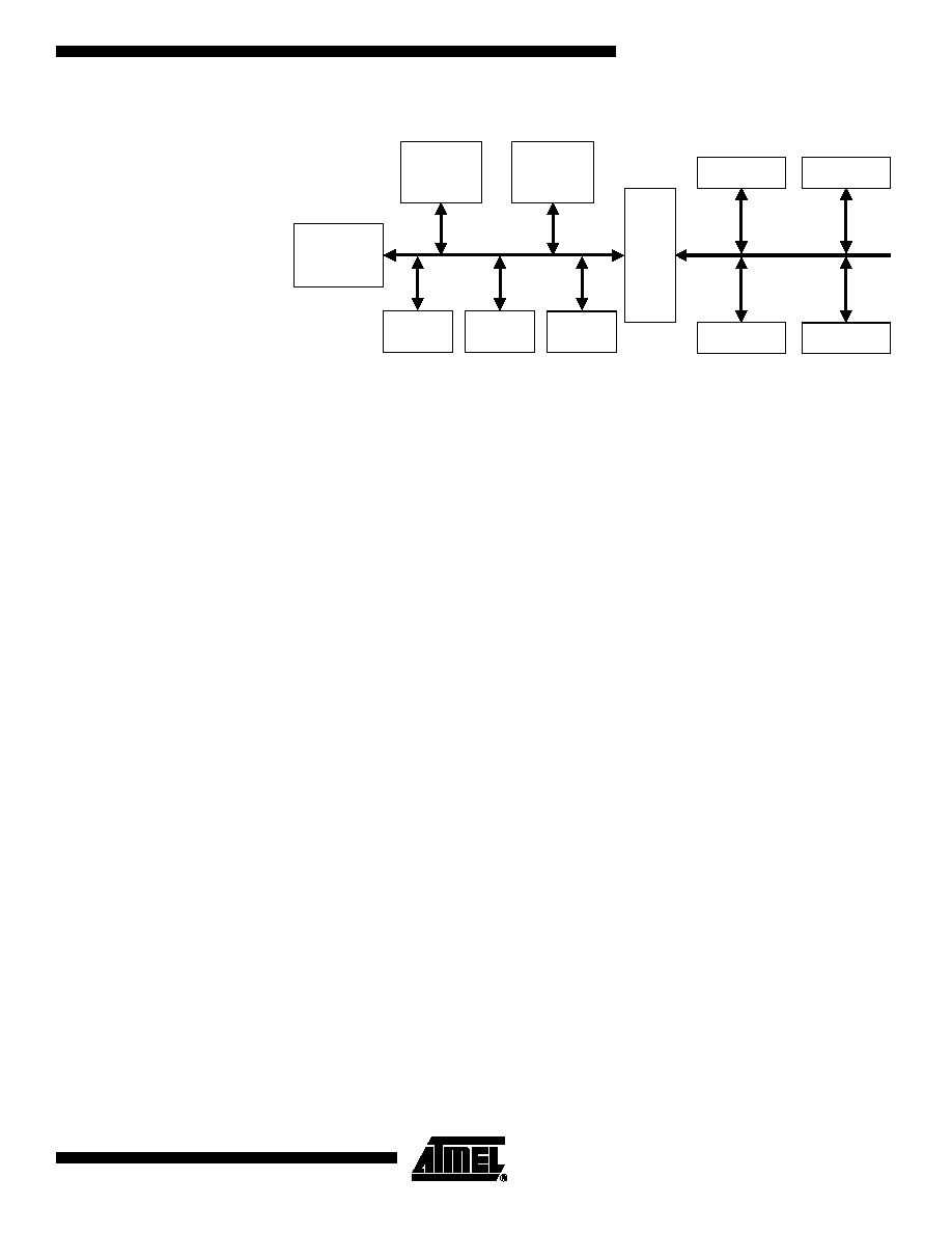
AMBA Hierarchy
A typical AMBA-based microcontroller is shown in Figure 2. The processor, on-chip
memory and external bus interface all reside on the high-performance system bus. This
bus provides a high bandwidth interface between the elements that are involved in the
majority of transfers. Also located on the high-performance ASB is a bridge to the lower
bandwidth APB, where most of peripherals in the system reside.
The APB provides the basic peripheral macrocell communications infrastructure as a
secondary bus from the higher bandwidth pipelined main system bus. Such peripherals
typically have interfaces that are memory-mapped registers, but have no high bandwidth
interfaces and are accessed under programmed control.
BSIZE[1:0]
Transfer Size. The transfer size signals indicate the size of the transfer, which may be byte, half-word or
word. The signals are driven by the active bus master and have the same timing as the address bus.
BTRAN[1:0]
Transfer Type. These signals indicate the type of the next transaction, which may be address-only, non-
sequential or sequential. These signals are driven by a bus master when the appropriate AGNTx signal is
asserted.
BWAIT
Wait Response. This signal is driven by the selected bus slave to indicate if the current transfer may
complete. If BWAIT is high, a further bus cycle is required; if BWAIT is low, then the transfer may complete
in the current bus cycle.
When no slave is selected, this signal is driven by the bus decoder.
BWRITE
Transfer Direction. When high, this signal indicates a write transfer and when low, a read transfer.
This signal is driven by the active bus master and has the same timing as the address bus.
DSELx
Slave Select. A signal from the bus decoder to a bus slave "x", which indicates that the slave device is
selected and a data transfer is required. There is a DSELx signal for each ASB bus slave.
PA[31:0]
APB Address Bus. This is the APB address bus, which may be up to 32 bits wide and is driven by the
peripheral bus bridge unit.
PRDATA[31:0]
APB Read Data Bus. The peripheral read data bus is driven by the selected peripheral bus slave during
read cycles (when PWRITE is low). This data bus may be up to 32 bits wide.
PWDATA[31:0]
APB Write Data Bus. The peripheral write data bus is driven by the peripheral bus bridge unit during write
cycles (when PWRITE is high).
PSELx
APB Select. A signal from the secondary decoder, within the peripheral bus bridge unit, to each peripheral
bus slave "x". This signal indicates that the slave device is selected and a data transfer is required. There is
a PSELx signal for each bus slave.
PSTB
APB Strobe. This strobe signal is used to time all accesses on the peripheral bus. The falling edge of
PSTB is coincident with the falling edge of BCLK.
PSTB_RISING
This signal can be used as a clock signal to time all write transfers into peripherals. PSTB_RISING is
derived from the rising edge of BCLK. PSTB_RISING changes only when a peripheral is accessed.
PWRITE
APB Transfer Direction. When high, this signal indicates an APB write access and when low, a read
access.
Table 1. Signal List (Continued)
Name
Description
5
System Architecture
1353C≠CASIC≠02/02
Figure 2. A Typical AMBA System
ASB and APB
The APB appears as a local secondary bus that is encapsulated as a single ASB slave
device. The APB provides a low-power extension to the system bus, which builds on
ASB signals directly.
The APB bridge appears as a slave module that handles the bus handshake and control
signal retiming on behalf of the local peripheral bus. By defining the APB interface from
the starting point of the system bus, the benefits of the system diagnostics and test
methodology can be exploited.
When is ASB Less
Appropriate than APB?
Building all peripherals as fully functional ASB modules is feasible but may not always
be desirable for the following reasons:
∑
In designs with a large number of peripheral macrocells, the increased bus loading
may increase power dissipation and sacrifice performance.
∑
Where timing analysis is required, the slowest element on the bus will limit the
maximum performance.
∑
Many simple peripheral macrocells need latched addresses and control signals as
opposed to the high-bandwidth macrocells, which benefit from pipelined signaling.
∑
Many peripheral functions simply require a selection "strobe", which conveys
macrocell selection and read/write bus operation without the requirement to
broadcast the high-frequency BCLK signal to every peripheral.
∑
Typically, macrocells will need some form of clock, which comes from a centralized
clock divider source. Low-power designs often benefit from a single programmable
prescaler and thus do not need a reference BCLK signal broadcast around the
integrated circuit.
When to Use ASB or APB
A full ASB interface is used for:
∑
Bus masters
∑
On-chip memory blocks
∑
External memory interfaces
∑
High-bandwidth peripherals with FIFO interfaces
∑
DMA slave peripherals
∑
A simple APB interface is recommended for:
∑
Simple register-mapped slave devices
∑
Very low power interfaces where clocks cannot be globally routed
∑
Grouping narrow-bus peripherals to avoid loading the system bus
High
Bandwidth
Memory
Interface
High
Performance
Processor
(Master 1)
High
Bandwidth
On-chip
RAM
ASB
to
APB
Bridge
UART
Keypad
Timer
PIO
Decoder
Master 2
Arbiter