
Rev. 4749B≠AUTO≠09/04
Features
∑
Capability of Single-wire Operation
∑
Hardware Fault Recognition
∑
Inputs with High Common-mode and Differential-mode Interference Rejection Above
100 V
PP
due to External Filters at the Receiver Input
∑
Immunity Against Electromagnetic Interference
∑
Immunity Against Ground-voltage Offsets < 6 V
∑
Ruggedized Against ESD by MIL-STD-883C, Method 3015
Benefits
Systems which employ this device have the following benefits compared to solutions
using discrete components:
∑
High Reliability
Applications
∑
Especially Suited for Truck and Van Applications
∑
Interface Between Truck and Trailer
∑
Interface Between Dashboard and Engine
Description
The CAN driver IC B10011S is a low-speed, high-level interface for 24 V (27 V) opera-
tion with transmission levels according to ISO WD 11992-1 (point-to-point interface
between trucks and trailers). It is developed for signal levels of 8/16 V and a speed of
up to 250 kbits/s.
This device allows transmission, that is insensitive to electromagnetic interference.
Such interferences may especially occur in truck applications where (due to the length
of the wires) high common-mode voltages (e.g., 50 ) can be coupled into the lines.
This device contains a fault recognition circuit that detects faults on one of the two
wires, which are normally used for transmission. If a fault occurs the operation can be
switched from double-wire to single-wire mode thus, allowing proper operation even if
one wire is broken, has a short-cut or a high series resistance.
Figure 1. Block Diagram
V
DD
+4.3 V
V
SS
V
CC
1
2
3
4
5
6
7
8
16
15
14
13
11
10
9
B10011S
Select
control
Error
control
Compa-
rators
Output
control
2.5 V
GND
12
CAN
Transceiver IC
B10011S
2
B10011S
4749B≠AUTO≠09/04
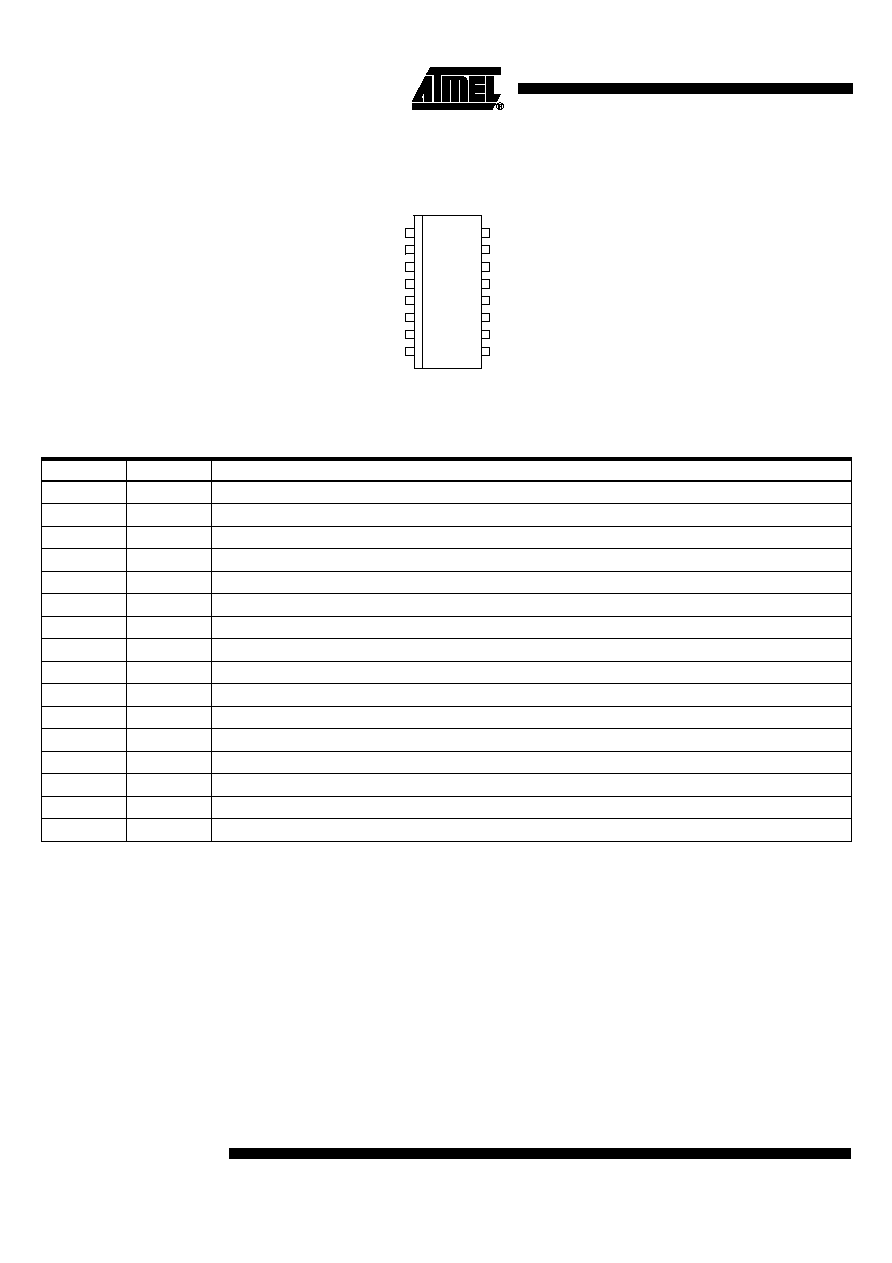
Pin Configuration
Figure 2. Pinning SO16
1
2
3
4
5
6
7
8
16
15
14
13
12
11
10
9
ASEL
BSEL
ER
RX1
RX0
TX0
VDD
VSS
F1
F0
S+
VCC
H'
L'
GND
S-
Pin Description
16-lead SOIC (SO16), Small Outline Gull - Wing
Pin
Symbol
Function
1
ASEL
Select control input
2
BSEL
Select control input
3
ER
Error signal output
4
RX1
Reference voltage 2.5 V
5
RX0
Receiver output
6
TX0
Transmitter input
7
VDD
Controller supply voltage 5 V
8
VSS
Controller supply voltage 0 V
9
S-
Collector of internal NPN switch
10
GND
Vehicle ground 0 V
11
L'
Data out driver
12
H'
Data out driver
13
VCC
Vehicle power supply 24 V
14
S+
Control output for external PNP
15
F0
Receiver input
16
F1
Receiver input

3
B10011S
4749B≠AUTO≠09/04
ER (error signal) is low when normal operation is disturbed by line faults (interruption,
short to ground or to V
CC
, H to L short disturbance by high voltage transients). After a
waiting period due to transient delays, the controller is asked to test if single-wire opera-
tion is possible by changing the A
sel
and B
sel
state.
A
sel
and B
sel
have an internal pull-up resistor. Therefore, the no-connect state is 1, but
connection to V
DD
is recommended when not in use.
Absolute Maximum Ratings
Stresses beyond those listed under "Absolute Maximum Ratings" may cause permanent damage to the device. This is a stress rating
only and functional operation of the device at these or any other conditions beyond those indicated in the operational sections of this
specification is not implied. Exposure to absolute maximum rating conditions for extended periods may affect device reliability.
Parameters
Symbol
Value
Unit
Supply voltage
V
CC
-0.5 to +36
V
Controller supply voltage
V
DD
-0.5 to +5.5
V
Input voltage at any input
V
in
-0.5 to V
DD
V
Junction temperature
T
j
150
∞C
Storage temperature range
T
stg
-55 to +150
∞C
Soldering temperature (for 10 s maximum)
T
sld
260
∞C
Operating Conditions
Parameters
Symbol
Value
Unit
Supply voltage car battery
V
CC
7 to 32
V
Controller supply voltage
V
DD
4.75 to 5.25
V
Control input voltage
A
sel
, B
sel
0 to V
DD
V
Input voltage
T
x0
0 to V
DD
V
Operating temperature
T
amb
-40 to +105
∞C
Operating Modes
0 = 0 V, 1 = 5 V
A
sel
B
sel
R
x0
Mode
0
0
3.8 V
H, L drivers disabled, L load disabled, S-, S+ disabled station not in operation, but
consuming current
1
0
From H
Single-wire H, L driver, L load, S-, S+ disabled
0
1
From L
Single-wire L, H driver disabled
1
1
From L-H
Two-wire operation, normal mode

4
B10011S
4749B≠AUTO≠09/04
Pulse Diagram
The pulse diagram for two connected, identical stations is shown below. The resistor
levels have to be kept constant when additional stations are connected.
Figure 3. Pulse Diagram
TX0
dominant
recessive
4 ms min
(1)
t
5 V
0 V
RX0
t
5 V
0 V
27 V
18 V
9 V
L
H
t
0 V
27 V
18 V
9 V
L'
H'
t
0 V
(1)
Filter has to be changed if short distances are to be allowed

5
B10011S
4749B≠AUTO≠09/04
Electrical Characteristics
Test condition: Test circuit (see Figure 4 on page 6), 0 = 0 V, 1 = 5 V
V
CC
= 27 V, V
DD
= 5 V, V
SS
= 0 V, T
amb
= -40∞C to +105∞C, unless otherwise specified.
Parameters
Test Conditions
Symbol
Min.
Typ.
Max.
Unit
Supply current
T
x0
= 0, A
sel
= 1, B
sel
= 1
I
CC
15
mA
T
x0
= 0, A
sel
= 0, B
sel
= 0
I
DD
22
mA
T
x0
= 1, A
sel
= 1, B
sel
= 1
I
CC
26
mA
T
x0
= 1, A
sel
= 1, B
sel
= 1
I
DD
16
mA
Input current
T
x0
= 1, A
sel
= 1, B
sel
= 1
I(T
x0
)
650
µA
T
x0
= 1, A
sel
= 1, B
sel
= 1
I(A
sel
, B
sel
)
150
µA
Output voltage
T
x0
= 0, A
sel
= 1, B
sel
= 0
V
IL
(F
0
) = 1.9 V, V
IH
(F
1
) = 2.7 V
R
x0
1.0
V
T
x0
= 1, A
sel
= 1, B
sel
= 1
V
IL
(F
1
) = 1.9 V, V
IH
(F
0
) = 2.7 V
R
x0
3.8
V
T
x0
= 0, A
sel
= 1, B
sel
= 1
U(H')
24.5
V
T
x0
= 1, A
sel
= 1, B
sel
= 1
U(H')
1.0
V
T
x0
= 1, A
sel
= 1, B
sel
= 1
U(L')
26
V
T
x0
= 0, A
sel
= 1, B
sel
= 1
U(L')
1.0
V
No fault
ER
4.7
V
Fault on line
ER
100
mV
V
CC
= 7 V, V
DD
= 4.75 V, V
SS
= 0 V, T
amb
= 25∞C, unless otherwise specified.
Parameters
Test Conditions
Symbol
Min.
Typ.
Max.
Unit
Output voltage
T
x0
= 0, A
sel
= 1, B
sel
= 1
U(H')
4.5
V
T
x0
= 1, A
sel
= 1, B
sel
= 1
U(H')
100
mV
T
x0
= 1, A
sel
= 1, B
sel
= 0
U(L')
6.5
V
T
x0
= 0, A
sel
= 1, B
sel
= 1
U(L')
1.0
V
T
x0
= 1, A
sel
= 1, B
sel
= 0
V
IL
(F
1
) = 1.0 V, V
IH
(F
0
) = 1.15 V
R
x0
3.3
V
T
x0
= 0, A
sel
= 1, B
sel
= 0
V
IL
(F
0
) = 1.0 V, V
IH
(F
1
) = 1.15 V
R
x0
1.0
V
V
CC
= 32 V, V
DD
= 5.25 V, V
SS
= 0 V, T
amb
= 25∞C, unless otherwise specified.
Parameters
Test Conditions
Symbol
Min.
Typ.
Max.
Unit
Output voltage
T
x0
= 0, A
sel
= 1, B
sel
= 1
U(H')
29
V
T
x0
= 1, A
sel
= 1, B
sel
= 1
U(H')
500
mV
T
x0
= 1, A
sel
= 1, B
sel
= 0
U(L')
31.5
V
T
x0
= 0, A
sel
= 1, B
sel
= 1
U(L')
1.0
V
T
x0
= 1, A
sel
= 1, B
sel
= 0
V
IL
(F
1
) = 1.6 V, V
IH
(F
0
) = 2.7 V
R
x0
4.0
V
T
x0
= 0, A
sel
= 1, B
sel
= 0
V
IL
(F
0
) = 1.6 V, V
IH
(F
1
) = 2.7 V
R
x0
1.0
V