 | –≠–ª–µ–∫—Ç—Ä–æ–Ω–Ω—ã–π –∫–æ–º–ø–æ–Ω–µ–Ω—Ç: U5021M | –°–∫–∞—á–∞—Ç—å:  PDF PDF  ZIP ZIP |

Rev. 4756C≠AUTO≠09/04
Features
∑
Low Current Consumption: I
DD
< 100 µA
∑
RC Oscillator
∑
Internal Reset During Power-up and Supply Voltage Drops (POR)
∑
"Short" Trigger Window for Active Mode,
"Long" Trigger Window for Sleep Mode
∑
Cyclical Wake-up of the Microcontroller in Sleep Mode
∑
Trigger Input
∑
Single Wake-up Input
∑
Reset Output
∑
Enable Output
Description
The digital window watchdog timer, U5021M, is a CMOS integrated circuit. In applica-
tions where safety is critical, it is especially important to monitor the microcontroller.
Normal microcontroller operation is indicated by a cyclically transmitted trigger signal,
which is received by a window watchdog timer within a defined time window.
A missing or a wrong trigger signal causes the watchdog timer to reset the microcon-
troller. The IC is tailored for microcontrollers which can work in both full-power and
sleep mode. With an additional voltage monitoring (power-on reset and supply voltage
drop reset), the U5021M offers a complete monitoring solution for microsystems in
automotive and industrial applications.
Digital Window
Watchdog Timer
U5021M
2
U5021M
4756C≠AUTO≠09/04
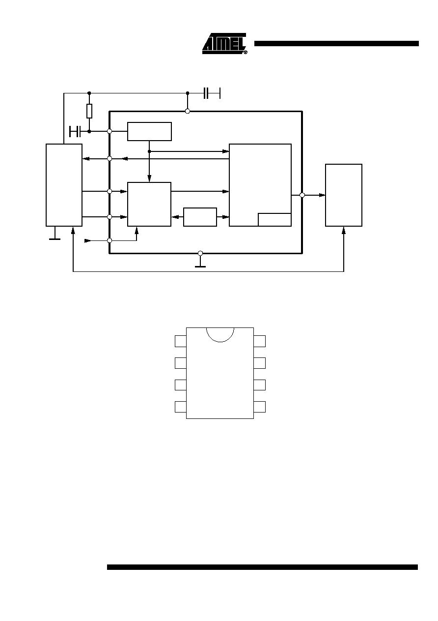
Figure 1. Block Diagram with External Ciruit
Pin Configuration
Figure 2. Pinning SO8
Input signal
conditioning
OSC
POR
3
2
Power-on
reset
5
Mode
Trigger
RC
Oscillator
State machine
POR
OSC
Reset
Micro-
controller
Test logic
1
Wake-up
External
switching
circuitry
4
7
Enable
GND
8
6
C
10 nF
R
1
V
DD
OSC
C
1
V
DD
1
2
3
4
WAKE-UP
TRIG
MODE
ENA
GND
VDD
OSC
RESET
5
6
7
8

3
U5021M
4756C≠AUTO≠09/04
Functional
Description
Supply Voltage, Pin 6
The U5021M requires a stabilized supply voltage V
DD
= 5 V ±5% to comply with its elec-
trical characteristics.
An external buffer capacitor of C = 10 nF may be connected between pin 6 and GND.
RC Oscillator, Pin 8
The clock frequency, f, can be adjusted by the components R
1
and C
1
according to the
formula:
where t = 1.35 + 1.57 R
1
(C
1
+ 0.01)
R
1
in k
, C
1
in nF and t in µs
The clock frequency determines all time periods of the logic part as shown in the table
"Electrical Characteristics" under the subheading "Timing" on page 9. With an appropri-
ate component selection, the clock frequency, f, is nearly independent of the supply
voltage as shown in Figure 3 on page 4.
Frequency tolerance
f
max
= 10% with R
1
±1%, C
1
= ±5%
Pin Description
Pin
Symbol
Function
1
WAKE-UP
Wake-up input (pull-down resistor)
There is one digitally debounced wake-up input. During the long watchdog window, each signal slope at
the input initiates a reset pulse at pin 5.
2
TRIG
Trigger input (pull-up resistor)
It is connected to the microprocessor's trigger signal.
3
MODE
Mode input (pull-up resistor)
The processor's mode signal initiates the switchover between the long and the short watchdog time.
4
ENA
Enable output (push-pull)
It is used for the control of peripheral components. It is activated after the processor triggers three times
correctly.
5
RESET
Reset output (open drain)
Resets the processor in the case of a trigger error or if a wake-up pulse occurs during the long watchdog
period.
6
VDD
Supply voltage
7
GND
Ground, reference voltage
8
OSC
RC oscillator
f
1
t
---
=
4
U5021M
4756C≠AUTO≠09/04
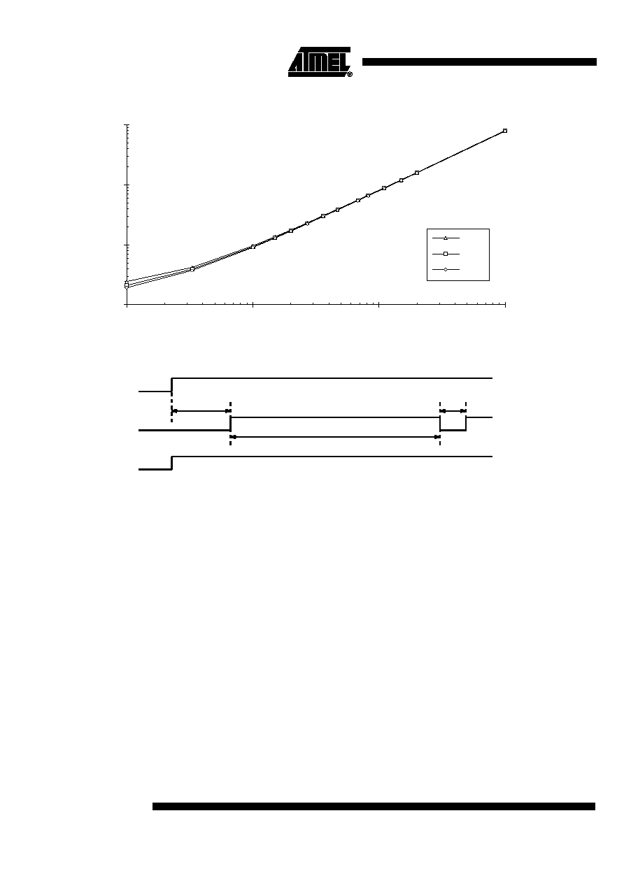
Figure 3. Period t versus R
1
, at C
1
= 500 pF
Figure 4. Power-on Reset and Switch-over Mode
Supply Voltage
Monitoring, Pin 5
During ramp-up of the supply voltage and in the case of supply-voltage drops the inte-
grated power-on reset (POR) circuitry sets the internal logic to a defined basic status
and generates a reset pulse at the reset output, pin 5. A hysteresis in the POR threshold
prevents the circuit from oscillating. During ramp-up of the supply voltage, the reset out-
put stays active for a specified period of time (t
0
) in order to bring the microcontroller into
its defined reset status (see Figure 4). Pin 5 has an open-drain output.
Switch-over Mode Time,
Pin 3
The switch-over mode time enables the synchronous operation of microcontroller and
watchdog. When the power-on reset time has elapsed, the watchdog has to be switched
to monitoring mode by the microcontroller by a "low" signal transmitted to the mode pin
(pin 3) within the time-out period, t
1
. If the low signal does not occur within t
1
(see Figure
4), the watchdog generates a reset pulse, t
6
, and t
1
starts again. Microcontroller and
watchdog are synchronized with the switch-over mode time, t
1
, each time a reset pulse
is generated.
1.00
10.00
100.00
1000.00
1
10
100
1000
t (µs)
C
1
= 500 pF
4.5 V
5.5 V
5.0 V
R
1
(k
)
t
0
Reset Out
Mode
VDD
Pin 6
Pin 5
Pin 3
t
1
t
6
5
U5021M
4756C≠AUTO≠09/04
Microcontroller in Active Mode
Monitoring with the "Short"
Trigger Window
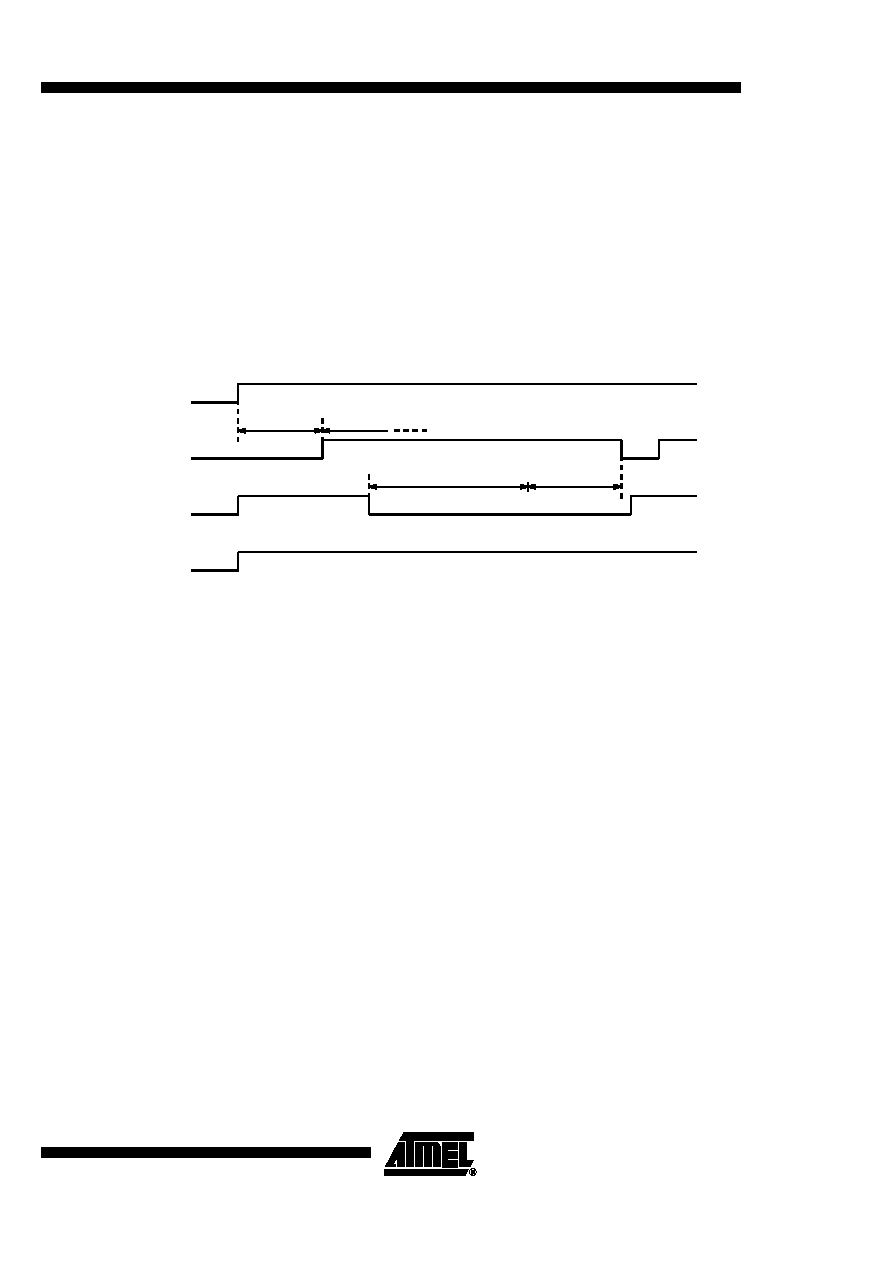
After the switch-over mode the watchdog operates in short watchdog mode and expects
a trigger pulse from the microcontroller within the defined time window, t
3
, (enable time).
The watchdog generates a reset pulse which resets the microcontroller if
∑
the trigger pulse duration is too long
∑
the trigger pulse is within the disable time, t
2
∑
there is no trigger pulse
Figure 5 shows the pulse diagram with a missing trigger pulse.
Figure 5. Pulse Diagram with no Trigger Pulse During the Short Watchdog Time
Figure 6 on page 6 shows a correct trigger sequence. The positive edge of the trigger
signal starts a new monitoring cycle with the disable time, t
2
. To ensure correct opera-
tion of the microcontroller, the watchdog needs to be triggered three times correctly
before it sets its enable output. This feature is used to activate or deactivate safety-criti-
cal components which have to be switched to a certain condition (emergency status) in
the case of a microcontroller malfunction. As soon as there is an incorrect trigger
sequence, the enable signal is reset and it takes a sequence of three correct triggers
before enable is active.
Microcontroller in Sleep Mode
Monitoring with the "Long"
Trigger Window
The long watchdog mode allows cyclical wake-up of the microcontroller during sleep
mode. As in short watchdog mode, there is a disable time, t
4
, and an enable time, t
5
, in
which a trigger signal is accepted. The watchdog can be switched from the short trigger
window to the long trigger window with a "high" potential at the mode pin (pin 3). In con-
trast to the short watchdog mode, the time periods are now much longer and the enable
output remains inactive so that other components can be switched off to effect a further
decrease in current consumption. As soon as a wake-up signal at the wake-up input
(pins 1) is detected, the long watchdog mode ends, a reset pulse wakes-up the sleeping
microcontroller and the normal monitoring cycle starts with the mode switch-over time.
t
0
V
DD
Mode
Trigger
Reset out
Pin 2
Pin 3
Pin 5
Pin 6
t
1
t
2
t
3