U642B
Rev. A4, 10-Apr-01
1 (7)
Interval- and Wipe/ Wash Wiper Control IC
Description
As a convenience feature of the windshield wiper
intermittent and wipe/wash operation are implemented in
most of the automobiles. The U642B is the low-cost
solution for an accurate timing function control.
Wipe/wash mode has priority over interval mode. Interval
pause and afterwiping time can be set to fixed values by
using resistors in a broad time range. Added value can be
provided with an individual, continuous adjustment of the
interval pause by a potentiometer which may be built into
the stalk. For proper operation it is mandatory to feed the
signal of the wiper motor`s park switch into U642B.
Features
D Interval pause: 4 to 20 s
D Afterwiping time: 2 to 20 s
D Wiper motor's park switch
D Wipe/wash mode priority
D One external capacitor, determines all time sequences
D Relay driver with Z-diode
D Interference protection according to VDE 0839 or
ISO/TR 7637/1
D Load-dump protected
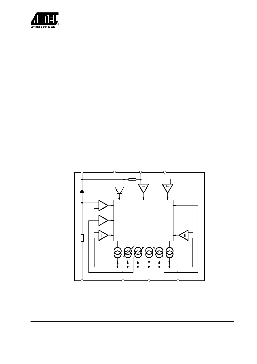
Block Diagram
Wipe / wash
comparator
Interval
comparator
Load-dump
comparator
VRef
V
Ref
VRef
Input
comparator
Park switch
comparator
VRef
8
7
6
5
4
1
2
3
A
B
C
D
E
F
Logic
VS
OUT
PARK
WASH
R
t
GND
INT
C
t
94 8950
Figure 1. Block diagram
U642B
Rev. A4, 10-Apr-01
2 (7)
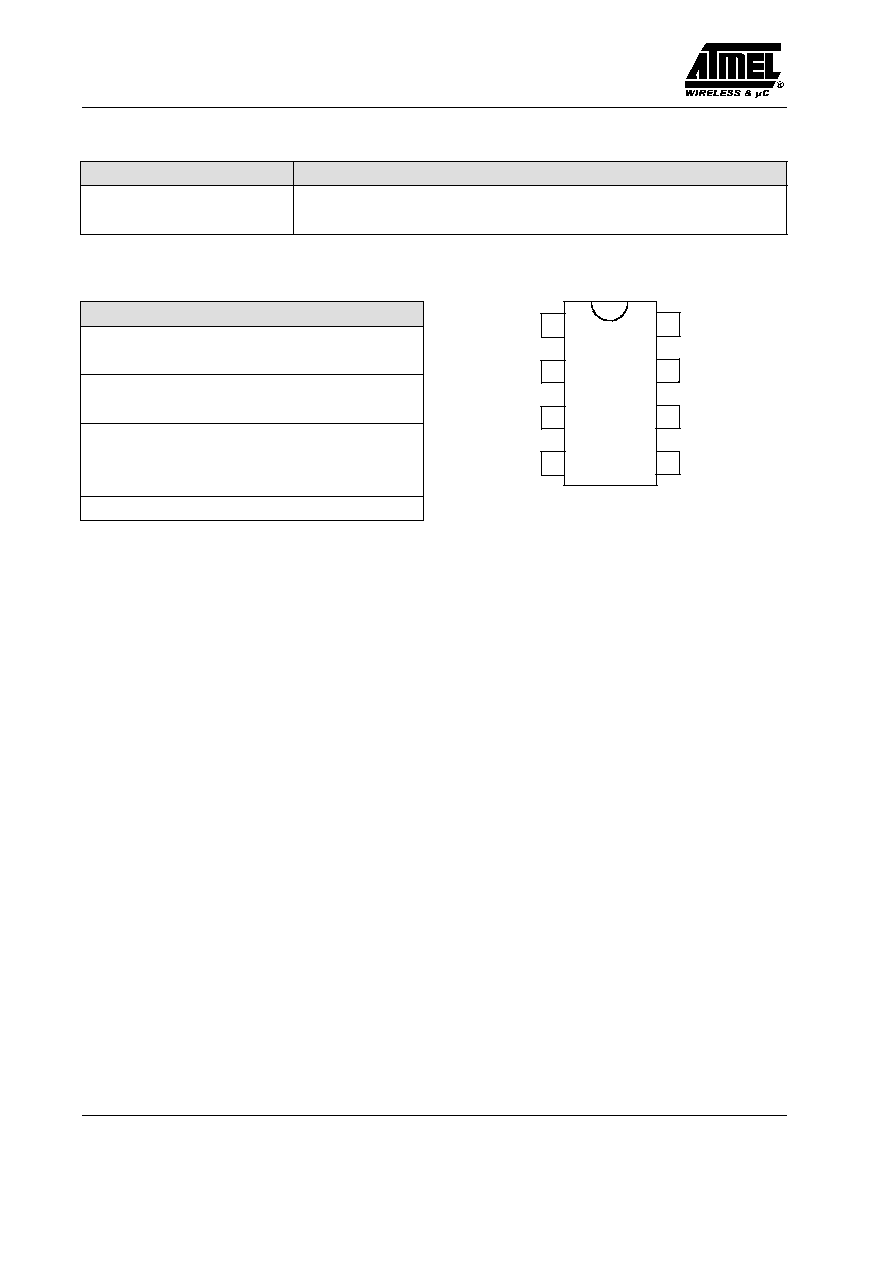
Ordering Information
Extended Type Number
Package
Remarks
U642B
DIP8
U642B≠FP
SO8
Pin Description
Pin
Symbol
Function
1
GND
Ground
2
INT
Interval switch
3
C
t
Timing capacitor C
2
4
R
t
Afterwiping time resistance
5
WASH
Wipe/Wash switch
6
PARK
Park switch for wiper motor
7
OUT
Relay control output
8
V
S
Supply voltage KI. 15
V
S
OUT
WASH
GND
INT
R
t
C
t
1
2
3
4
8
7
6
5
U642B
93 7691
PARK
Figure 2. Pinning
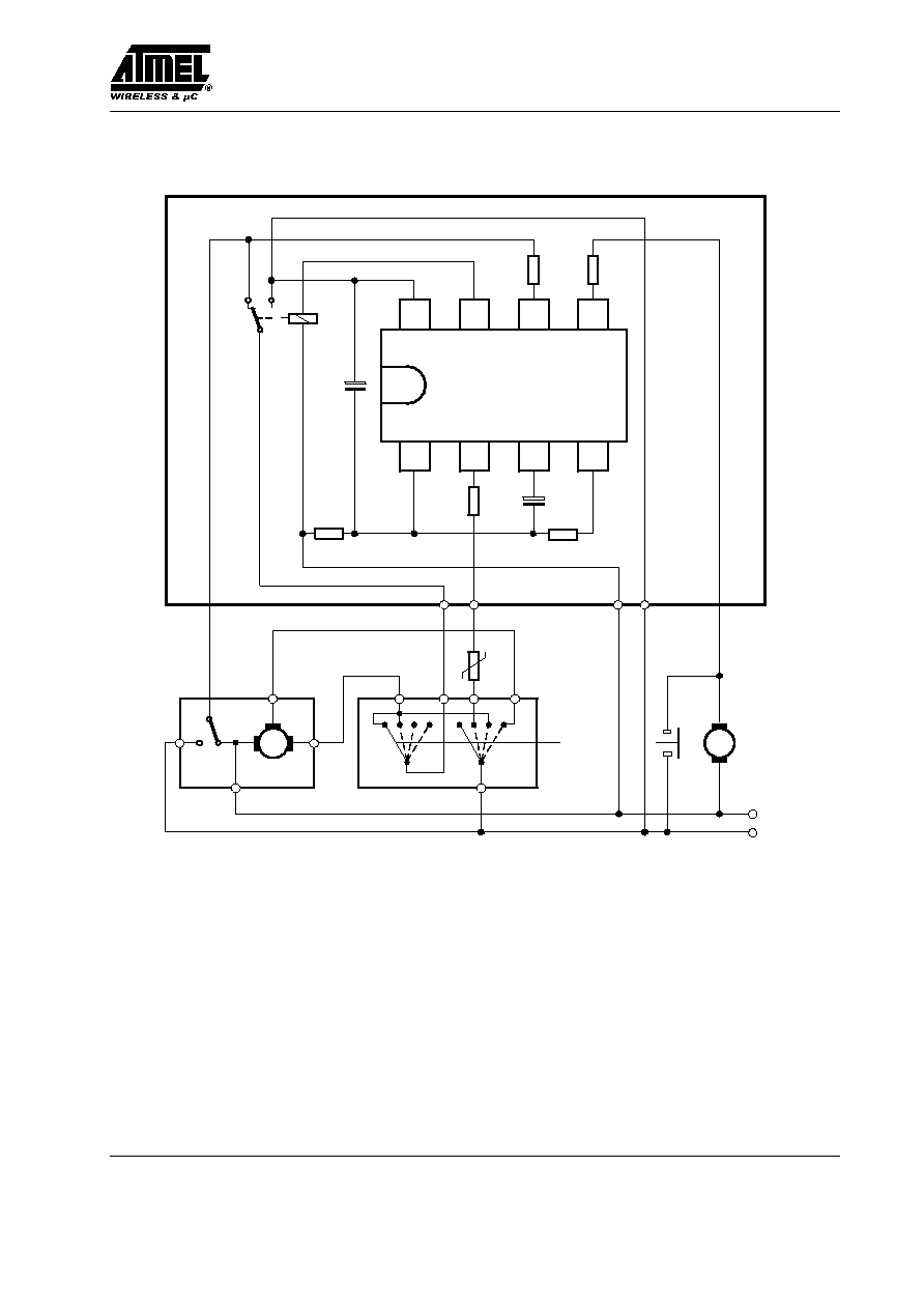
Circuit Description
Interval Function, Pin 2
By closing the interval switch, S
2
, to supply voltage,
V
Batt
, the relay is activated. The internal current source
(Pin 3) which holds the capacitor C
2
in charged state is
switched-off. As soon as there is a positive potential at the
park switch (S
1
), the current source F (see figure 1)
charges the capacitor C
2
very fast. After the wiper
operation is finished, S
1
is again at ground potential, the
relay is in "off" position ≠ interval pause begins ≠ the
capacitor C
2
is discharged through the current source C,
till the voltage at Pin 3 is below the threshold of 2 V.
Interval pause can be adjusted between 4 s to 20 s with the
help of potentiometer R
3
. Now the relay switches on and
the next interval cycle begins. Opening of switch S
2
causes the current source A to discharge C
2
immediately
and current sources C and F are switched-off.
Wipe/Wash (WIWA) Operation, Pin 5
By closing the WIWA-switch, S
3
, to supply voltage,
V
Batt
, the water pump starts spraying water on the wind-
screen, the current source A is switched-off which keeps
the capacitor C
2
in discharged state. Now the capacitor is
charged through the current sources D and F, and when af-
ter a time interval of approximately 100 ms, the voltage
at the capacitor is greater than 6.5 V, the relay is turned
on as long as the switch "WIWA" is closed.
The after-wipe-time begins after the switch is open
whereas the sources D and F are switched off and the
source E is activated. Source E discharges the capacitor
till the voltage is less than 2.2 V. The relay is off and the
wiper-motor is supplied via the park switch until the park
position will be reached. The after-wipe-time is
determined by the current source E which can be
regulated with the external resistor R
Time
. Afterwards the
source A discharges the capacitor. The relay switch off is
independent of the park switch S
1
.
Interval and WIWA Functions
The interval function is interrupted immediately when the
wipe/ wash mode is activated. The current source A dis-
charges the capacitor to a value of 2 V, afterwards the
normal wash function starts.
Interval wiping starts immediately when the after-wipe-
time is over. The switching delays are slightly shorter,
because the capacitor is already charged to a value of 2 V.
The wipe/ wash function is not interrupted when interval
switch S
2
is activated. Interval function begins after the
WIWA function is over.

U642B
Rev. A4, 10-Apr-01
4 (7)
Absolute Maximum Ratings
Parameters
Symbol
Value
Unit
Supply voltage
t = 60 s
Terminal 15, Pin 8
V
Batt
28
V
Supply current
t = 2 ms
Pin 8
t = 200 ms
I
8
I
8
1.5
150
A
mA
Relay control output current (DC)
Pin 7
t = 200 ms
I
7
I
7
200
1.2
mA
A
Pulse current (control inputs)
t = 200 ms
Park switch, S
1
Pin 6
Wipe/Wash switch, S
3
Pin 5
Interval switch, S
2
Pin 2
I
6
I
5
I
2
50
50
50
mA
Power dissipation
T
amb
= 90
∞
C
P
tot
500
mW
Storage temperature range
T
stg
≠55 to +125
∞
C
Ambient temperature range
T
amb
≠40 to +85
∞
C
Thermal Resistance
Parameters
Symbol
Value
Unit
Junction ambient
DIP8
SO8
R
thJA
R
thJA
120
160
K/W
K/W
Electrical Characteristics
V
Batt
= 12 V, T
amb
= 25
∞
C, reference point is Pin 8 (see figure 3) unless otherwise specified.
Parameters
Test Conditions / Pins
Symbol
Min.
Typ.
Max.
Unit
Supply voltage
Pin 8
V
Batt
9
16.5
V
Supply current
I
8
10
mA
Z-diode limitation
V
1
7.6
V
Overvoltage
Threshold current
I1
≠50
mA
Threshold voltage
V
Batt
35
V
Relay control output
Pin 7
Saturation voltage
I
7
= 100 mA
I
7
= 200 mA
V
7
≠1.0
≠1.5
V
Leakage current
I
7
100
mA
Park switch
Pin 6
Internal pull-up resistance
R
6
= 10 k
W
R
6
50
k
W
Switching threshold voltage
V
6
≠3.3
V
Protection diode
I
6
= ≠10 mA
I
6
= 10 mA
V
6
V
6
≠0.8
7.6
V
V
Input C
t
Pin 3
Internal resistance
R
3
100
W
Interval input, R
2
= 2.7 to 30 k
W
Pin 2
Protection diode
I
2
= ≠10 mA
I
2
= 30 mA/10 ms
V
2
≠0.8
7.6
V

U642B
Rev. A4, 10-Apr-01
5 (7)
Electrical Characteristics (continued)
V
Batt
= 12 V, T
amb
= 25
∞
C, reference point is Pin 8 (see figure 3) unless otherwise specified.
Parameters
Test Conditions / Pins
Symbol
Min.
Typ.
Max.
Unit
WASH Input, R
5
= 10 k
W
Pin 5
Switching threshold/Hysteresis
V
5
≠1.4/≠5.4
V
Protection diode
I
5
= ≠10 mA
I
5
= 10 mA
V
≠0.8
7.6
V
Switching Characteristics, R
4
= 47 k
W to 300 kW, I
4
= ≠150
mA
Interval time
R
3
= 0 k
W
R
3
= 10 k
W
t
2
3.6
10.8
4
12
4.4
13.2
s
Prewash delay
t
del
100
ms
After-wipe-time
R
4
= 130 k
W Pin 5
t
5
4.75
5.25
5.75
s
0
2
4
6
8
10
12
≠40
≠20
0
20
40
60
80
100
Interval pause ( s )
Temperature (
∞
C )
14005
R
int
= 0
R
int
= 5 k
W
R
int
= 10 k
W
Figure 4. Interval pause = f ( T); Ct = 22
mF
0
2
4
6
8
10
12
≠40
≠20
0
20
40
60
80
100
Afterwiping time ( s )
Temperature (
∞
C )
14006
R
time
= 51 k
W
R
time
= 130 k
W
R
time
= 300 k
W
V
Batt
= 8 V
Figure 5. Afterwiping time = f ( T); Ct = 22
mF
0
2
4
6
8
10
12
14
16
0
2
4
6
8
10 12 14 16 18 20
Interval pause (s )
Interval resistor ( k
W )
14009
Figure 6. Interval pause = f ( R
INT
); Ct = 22
mF
0
2
4
6
8
10
12
≠40
≠20
0
20
40
60
80
100
Afterwiping time ( s )
Temperature (
∞
C )
14007
R
time
= 51 k
W
R
time
= 130 k
W
R
time
= 300 k
W
V
Batt
= 16 V
Figure 7. Afterwiping time = f ( T); Ct = 22
mF